1
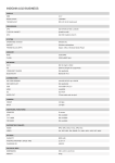
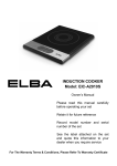
User Manual of
C10 Series Repeaters
User Manual of
C20-GSM
Repeaters
CATALOGUE
CHAPTER 1 SAFETY WARNING.............................................................................................. 2
CHAPTER 2 SUMMARY ............................................................................................................. 3
CHAPTER 3 SPECS AND FEATURES ...................................................................................... 4
3.1 PRODUCT DESCRIPTIONS ............................................................................................................................ 4
3.2 FEATURES .................................................................................................................................................... 4
3.3
SYSTEM DIAGRAM ................................................................................................................................ 4
3.4
ELECTRICAL SPECIFICATION ............................................................................................................... 5
3.5
MECHANICAL SPECIFICATION ............................................................................................................. 5
3.6
APPEARANCE DIAGRAM ....................................................................................................................... 6
3.7
PORTS ................................................................................................................................................. 6
CHAPTER 4 INSTALLATION .................................................................................................... 7
4.1 INSTALLATION REQUIREMENTS ................................................................................................................. 7
4.2 INSTALLATION............................................................................................................................................. 8
4.3
CONNECTION ...................................................................................................................................... 10
5.1
POWER SUPPLY CONNECTION ............................................................................................................ 11
5.2
PERFORMANCE SETTING .................................................................................................................... 11
CHAPTER 6 PRODUCE MAINTENANCE............................................................................. 12
6.1 OPERATION AND MAINTENANCE .............................................................................................................. 12
6.2 EMERGENCY DEALING .............................................................................................................................. 13
6.3 MAINTAINING DIRECTIONS ...................................................................................................................... 13
1
User Manual of
C20-GSM
Repeaters
Chapter 1 Safety Warning
Users must follow the below principles:
1 Repeater should follow system requirement of communication equipment, assure good
groundings and lightning protection.
2 The power supply voltage of repeater should meet the standards of security requirement; any
repeater-operator can operate only after cutting power in advance. Only the professional can
operate electrified.
3 Do not dismantle machine, maintain or displace accessories by yourself, because in this way,
the equipment may be damaged or even get an electric shock.
4 Do not open the repeaer, touch the module of repeater, even not to open the cover of module to
touch the electronic component, the components will be damaged due to electrostatic
5 Please keep away from heating-equipment, because the repeater will dissipate heat when
working. And do not cover repeater with anything that influences heat-dissipation.
2
User Manual of
C20-GSM
Repeaters
Chapter 2 Summary
In mobile communication, it is inevitable that macro-cell coverage cannot cover weak or dead
zones; to use repeater is a good choice in these areas. Wide band consumer repeaters mainly
applied in covering small blind and weak zones
C10 series repeater is a good choice for weak signal area of GSM system ,such as VIP
rooms , offices, houses, restaurants, apartments, packing, etc.
3.1 Application
C10 series repeater enhances consumer satisfaction greatly with its integrated design,
compact size, easy engineering and rapid installation and debugging,
3
User Manual of
C20-GSM
Repeaters
Chapter 3 Specs and features
3.1 Product descriptions
(1) In Terminal: N- Female
(2) LED: To monitor the status of power on/off and normal operation
(3) Power Supply Terminal: External type AC-DC power supply
(Operating voltage: 9 V/2A )
3.2 Features
Compact design and light weight, cost effectiveness
LED indication for operation status.
Selective band function to work on GSM support.
Low power consumption, Low interference.
Applicable to In-Building with medium or small size with Maximum coverage up to
1200 Square meters, such as VIP room, office, house, restaurants, apartments, parking.
ALC to limit output power at specified power level and ensure stable coverage effect.
3.3 System diagram
4
User Manual of
C20-GSM
Repeaters
3.4 Electrical Specification
C10 series
Electrical specification
Frequency Range
Output Power
Max.Gain
In-band Ripple
Spurious 9KHz~1GHz
Emission 1GHz~12.75GHz
Noise Figure
VSWR
Group Delay
Weight
Dimensions (D x W xH )
Environment Conditions
Impedance
Power Supply
Working Temperature
Humidity
2 Alarm
Power LED
LED
indication Alarm LED
specification
GSM900,or GSM1800,or WCDMA
UL 10dBm DL 10dBm
UL 60dB DL 60dB
6dB
-40dBm @ 3KHz
-40dBm @ 3KHz
6dB
2
0.5µs
1.5Kg
209*133*41mm
IP40
50 Ohms
AC:120V; DC:9V2A Adapter
-25 to +55
5 -95
specification
DC ON/OFF
ALC 1~5dB,orange
ALC 20~25dB,red
3.5 Mechanical Specification
Environment Conditions
IP40
Weight
<1kg
Dimensions (W x H x D)
Operating Temperature
134*218*57mm
-10~50 ºC
5
User Manual of
C20-GSM
Repeaters
3.6 Appearance Diagram
3.7 Ports
6
User Manual of
C20-GSM
Repeaters
Chapter 4 Installation
4.1 Installation requirements
C10 series repeaters are mainly applied as indoor coverage GSM system. After connection
of equipment and antenna, the distance of them should be keep as far away as possible, it’s
better that there is a wall as the obstruct between them.
7
User Manual of
C20-GSM
Repeaters
Position selection
Install in the place that is not easy to be reached by irrelevant people.
Install at the place that is convenient for power supply and cabling
Avoid heat source and moist environment
Power supply requirement
AC power supply of 9V/2A
Installation
4.2 Installation
component 1
8
User Manual of
C20-GSM
Repeaters
installation step 1
Installation step 2
9
User Manual of
C20-GSM
Repeaters
component 1
component 2
Installation step 3
Installation Steps:
1 :Use percussion drill to make four Φ6 holes on the wall according to above hole diagram,
fasten component 1 onto the wall.
2: Put the component 2 into component 1
4.3 Connection
Connection of RF cable
Input Port: put the antenna outdoor, and try to put on the place where there is strong signal,
then connect one adapter to BTS of equipment and assure good connection.
Power supply connection
Please use three-pin plug to assure good grounding
Chapter 5
Repeater setting
10
User Manual of
C20-GSM
Repeaters
Please check whether the connection of RF cable is correct (donor antenna connected to
BTS port, service antenna connected to MS port), and whether every port is stable. After
affirmation, please go along the followings:
5.1
Power supply connection
After power supply connection, check ALARM and POWER and PA failure indicators first.
Status and definition of POWER indicators:
Status
Definition
green
Normal
off
DC power problem
Status and definition of ALARM indicators:
Status
Definition of ALARM
Meaning: working in linearity
green
attention: Input signals may be not enough
Meaning: overloading or self oscillation, strong input signals
Attention: cut the connection of equipment and service antenna,
then connect the MS port to load, if the red light changes to green
red
or orange, which means the isolation of donor antenna and service
antenna is not enough, then please adjust the isolation.
If the red light still turning on that means over accepting of donor
antenna or strong interference, then please adjust the place of
donor antenna..
5.2
orange
Meaning: it is working in linearity
off
Repeater break down
Performance setting
Curve chart of equipment working condition
11
User Manual of
C20-GSM
Repeaters
POutput Power
Edge Point
Pmax
(Pinput Power-VATT)
Green: Linear
amplification
Orange:
Red:
Overloading
stable
Picture 3: Curve of output power, input signal and attenuation value
POutput Powe: output power
Pinput Power: input power
VATT: attenuation vale
Pinput Power -VATT: input power—attenuation value
Pmax: output power rating
Chapter 6 Produce Maintenance
6.1 Operation and maintenance
Power supply
Please make sure the voltage and frequency comply with the repeater requirement.
Component replacement
Please do not maintain or replace components by yourself, otherwise may get an electric
shock. Only the authorised professional can maintain and replace the components.
12
User Manual of
C20-GSM
Repeaters
Waterproof and moist proof
Please do not turn on or off the booster in moist environment when its door is opened.
6.2 Emergency dealing
Switch off is recommended during following situations:
The power supply is not normal
Liquid flows into the equipment;
Working conditions is not normal, (overheating, abnormal smelling, abnormal sundries)
Closet damage
performance decreasement
near to fire
flooding
6.3 Maintaining directions
Please check the booster step by step according to below process, to find out the problem with the
repeater.
Abnormal performance
LED check
Green
Red
Off
Abnormal
Improve the feeder
system
Abnormal
Feeder system
inspection
Isolation inspection
Power supply
inspection
Improve the
power supply
Strong interference
near donor antenna
Normal
Normal
Contact repeater
supplier
13
C10-GSM
Electrical specification
Frequency Range
specification
GSM900
Max.Gain
Automatic Level Control
Gain Flatness
Output Power
Intermodulation 9KHz~1GHz
Products
1GHz~12.75GHz
9KHz~1GHz
Spurious
Emission
1GHz~12.75GHz
Noise Figure
VSWR
Group Delay
Weight
Environment Conditions
DC Supply
2 Alarm
Power LED
LED indication
Alarm LED
UL:890~915MHz DL:935~960MHz
UL 60dB DL 60dB
20dB
8dB
10dBm
-36dBm@ 3KHz
-30dBm @ 3KHz
-36dBm @ 3KHz
-30dBm @ 3KHz
6dB
2.5
1.5 s
1Kg
IP40
9V2A (AC:165V~265V,50/60Hz)
specification
DC ON/OFF
ALC 1~5dB,orange
ALC 20~25dB,red
NOTIFIED BODY STATEMENT OF OPINION
R&TTE DIRECTIVE 1999/5/EC
Conformity assessment procedure Article 10(4) and Annex IV
DESCRIPTION OF THE PRODUCT
Manufacturer
:
Foshan Amplitec Tech Development Co., Ltd.
Address
:
No.1 Room, Second Floor, No.40, First East Tonghua Rd.
Foshan City, Guangdong, China
Phone number
:
86-757-8332-3709
Product description
:
Mobile Phone Signal Amplifier
Intended use
:
GSM/WCDMA REPEATER
Product Specifications
:
See ANNEX 1
Brand
:
AMPLITEC
Type/Model number
:
C10,C10H,C15,C20,C10H-GD,C10H-GSM,C10H-DCS, C10H-WCDMA,
C10-2B,C10-GW,C10-GSM,C10-DCS,C10-WCDMA,C10D-GDW,C10GD,C15-GSM,C15-DCS,C15-WCDMA,C20-WCDMA,C20-GSM,C20-DCS
TECHNICAL CONSTRUCTION FILE
:
Issued by
Foshan Amplitec Tech Development Co., Ltd.
Address
:
No.1 Room, Second Floor, No.40, First East Tonghua Rd.
Foshan City, Guangdong, China
Phone / Fax number
:
86-757-8332-3709 / 86-757-8312-3923
Signed by
:
LIU Sunping
Project Manager
Date
:
09/20/2008
File Number
:
SZAGC288080801
TIMCO NOTIFIED BODY STATEMENT OF OPINION
Issued by
:
Notified Body 1177, TIMCO Engineering, Inc.
Date
:
October 9, 2008
Opinion number
:
TCF-2300CC8 (Original TCF-2248CC8)
On behalf of
:
The President of TIMCO Engineering, Inc.
Signature
Name
:
:
Bruno Clavier
The device shall be marked as follows:
THIS STATEMENT OF OPINION HAS NO ADDENDUM.
Based on the evidence presented in the Technical Construction File, TIMCO Engineering, Inc., as appointed Notified
Body (number 1177), has given a positive opinion that the product described is in conformity with the essential
requirements Article 3.2, 3.1a, and 3.1b of R&TTE Directive 1999/5/EC.
TIMCO ENGINEERING, INC.
P.O. BOX 370
NEWBERRY, FL 32669
Tel.: 1-888-472-2424
Fax: 1-352-472-2030
E-mail: [email protected]
Designated as a U.S.
CAB by NIST National
Institute of Standards and
Technology
An agency of the U.S.
Commerce Department
This Opinion is issued under the provision that TIMCO
Engineering Inc. nor its subsidiary companies accept any
liability concerning the contents of this document other than
forced by law.
Reproduction of the Opinion (with addendum) in full is
allowed. Reproduction of parts of this certificate may only be
allowed by written permission of TIMCO Engineering, Inc.
ANNEX 1 TO STATEMENT OF OPINION NUMBER: TCF-2300CC8
Date
:
October 9, 2008
PRODUCT SPECIFICATIONS
RF output power (Cond.)
Frequency band
Modulation
Antenna type
:
:
:
:
UL: 5dBm, DL: 10dBm
UL: 890-915MHz, DL: 935-960MHz
GMSK, CDMA
Integral
RF output power (Cond.)
Frequency band
Modulation
Antenna type
:
:
:
:
UL: 5dBm, DL: 10dBm
UL: 1710-1785MHz; DL: 1805-1880MHz
GMSK, CDMA
Integral
TIMCO ENGINEERING, INC.
P.O. BOX 370, NEWBERRY, FLORIDA 32669
Telephone: 1-888-472-2424; Fax: 1-352-472-2030
E-mail: [email protected]