1
Wiring
Calibration
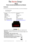
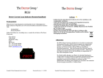
Please refer to the unit label if the screw terminal
layout is different to that shown below.
Power +
Power -
The display module must be powered and connected to a current-loop
source before calibration can begin. The relays do not require connecting
during calibration or relay setup. Calibration and relay settings are
configured using the 2 buttons at the rear of the module.
Settings are saved to a non-volatile memory and are reinstated after powerup. Re-calibration may be required if additional equipment is added to the
current-loop circuit at a later stage.
Relay 2
Relay 2
Left hand button
Right hand button
Power +
Power Relay 1
Relay 1
Current loop +
Current loop The displayed output is assumed to have a linear relationship with the input.
Therefore, calibration requires recording just two input levels and selecting
the desired displayed output for these inputs. Any two inputs could be used,
but for greatest accuracy they should be as far apart as possible. 4mA and
20mA settings are assumed in the following example, but the actual inputs
can differ.
Copyright © Deeter Engineering Services Limited
Document Revision 1.2 24/02/09
Copyright © Deeter Engineering Services Limited
Document Revision 1.2 24/02/09