1
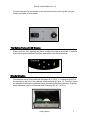
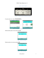
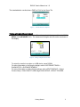
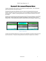
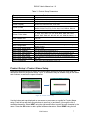
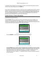
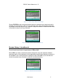
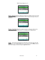
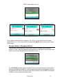
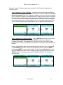
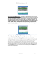
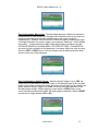
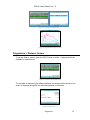
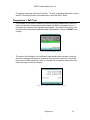
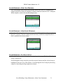
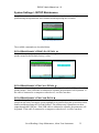
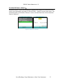
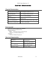
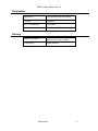
D25® NC User’s Manual Hunter Associates Laboratory 11491 Sunset Hills Road Reston, Virginia 20190 USA www.hunterlab.com A60-1016-487 Manual Version 1.0 For Firmware Version 1.10.14.073A & Above An ISO 9001 Certified Company D25 NC User's Manual ver 1.0 Copyrights and Trademarks This documentation contains proprietary information of Hunter Associates Laboratory, Inc. Its reproduction, in whole or in part, without express written consent of Hunter Associates Laboratory, Inc. is prohibited. Windows is a registered trademark of Microsoft Corporation in the United States and other countries. Safety Notes For safety when using the color measurement equipment, pay particular attention to the following types of statements in the hardware section of this User’s Manual. Each description is shown in its representative typeface. ii D25 NC User's Manual ver 1.0 TABLE OF CONTENTS CHAPTER 1 - GETTING STARTED .................................................................... 1 What is the D25 NC? .......................................................................................................................1 Unpacking & Connecting the D25 NC ............................................................................................1 The Button Pad & LCD Display ......................................................................................................2 Standardization ...............................................................................................................................2 Taking A Simple Measurement ......................................................................................................4 Additional Components & Accessories ...........................................................................................4 CHAPTER 2 - EDIT PRODUCT ............................................................................ 6 Product Name Setup ........................................................................................................................7 Product Standards ............................................................................................................................8 AutoSearch .......................................................................................................................................9 Views .............................................................................................................................................10 Standard Values .............................................................................................................................14 Tolerances ......................................................................................................................................15 Run Configuration .........................................................................................................................17 CHAPTER 3 - SYSTEM SETTINGS > GLOBAL OPTIONS ............................ 21 Language ........................................................................................................................................21 Locked Setups ...............................................................................................................................25 STDZ Interval ...............................................................................................................................26 AutoSearch ....................................................................................................................................27 Measurement Settings ...................................................................................................................28 Display Settings ............................................................................................................................29 Date/Time ....................................................................................................................................29 CHAPTER 4 - SYSTEM SETTINGS > DIAGNOSTICS..................................... 25 White Tile Repeatability ................................................................................................................25 Green Tile Check ...........................................................................................................................26 Signal Levels ..................................................................................................................................27 Distance Sensor ..............................................................................................................................28 Self Test .........................................................................................................................................29 CHAPTER 5 - SYSTEM SETTINGS > SAVED READINGS, SETUP & MAINTENANCE, ABOUT YOUR INSTRUMENT ......................................... 30 System Settings > Saved Readings ................................................................................................30 Saved Readings > Delete All Readings ....................................................................................30 Saved Readings > Print All Readings .......................................................................................31 Saved Readings > View Saved Readings .................................................................................31 iii D25 NC User's Manual ver 1.0 Saved Readings > Filter by Setup .............................................................................................31 System Settings > SETUP Maintenance ........................................................................................32 Setup Maintenance > Reset All Setups ...............................................................................32 Setup Maintenance > Print all Setups ..................................................................................32 Setup Maintenance > Print one Setup ...................................................................................32 System Settings > About Your Instrument ..................................................................................33 CHAPTER 6 - MAINTENANCE ........................................................................ 334 Routine Maintenance Schedule....................................................................................................334 System Warm-Up.........................................................................................................................334 Cleaning the Sensor .....................................................................................................................334 Cleaning the Instrument Standards ..............................................................................................335 Replacing the Fuses .....................................................................................................................335 CHAPTER 7 - SPECIFICATIONS ....................................................................... 37 Physical Characteristics .................................................................................................................37 Environmental ..........................................................................................................................37 Electrical Characteristics ...............................................................................................................38 Input/Output (I/O) ..........................................................................................................................38 Viewing ..................................................................................................................... 38 CHAPTER 8 - INSTRUMENT REPLACEMENT, REPAIR, PROBLEMS AND QUESTIONS ......................................................................... 39 Warranty…………..………..……..……………………………………………… ..................... 39 Shipping Claims .......................................................................................................................... 39 Breakage or Damage ..................................................................................................................... 39 Freight or Express ......................................................................................................................... 39 Parcel Post Shipment .................................................................................................................... 40 United Parcel Service .................................................................................................................... 40 Shortage .......................................................................................................................... 40 Incorrect Shipment ........................................................................................................................ 40 Returns ……………………………………………………………………..…… ........ 40 iv D25 NC User's Manual ver 1.0 Chapter 1 - GETTING STARTED What is the D25 NC? The D25 NC is a continuous, automated, non-contact color measurement instrument with height detection and color compensation. For use in laboratory environments, the D25 NC uses LED illumination technology to measure samples and monitor color on a rotating tray. Pour, place and measure single or multiple samples on the tray, with easy cleanup and maintenance. D25 NC makes real-time color measurements of products with irregular shapes, and in industries as diverse as paint, food, building products and industrial minerals. This instrument is designed to work as a stand-alone unit with an easy-to-read display or connected to EasyMatch QC software on a PC. Unpacking Connecting the D25 NC Unpack the Instrument and set stand and sensor on the bench top. The following items should be in the box: Item 1 2 3 4 5 6 7 8 9 10 11 12 13 14 Table 1. Shipping Contents Description Sensor head Calibration Box D25 NC Workstation Sample Tray, 150mm (6-in) Sample Tray, 300mm (12-in) with D04-1016-472 Hub USB Adapter Cable (Standard-A receptacle to Standard B plug, 1 meter long) connects the A/B receptacle on the instrument to other peripherals such as a Personal Computer or the A13-1014259 USB Printer. AC Input Cord, 110V AC Input Cord, 220V Documents Package D25 NC Certificate of Traceability D25 NC Sensor Report D25 NC Standards Data Sheet D25 NC Inter-Connect Drawings CD Contents D25 NC Quick Start Guide on CD A60-1016-531 D25 NC User’s Guide on CD A60-1016-487 Getting Started Part No. D02-1016-442 D02-1015-807 D02-1016-154 D04-1016-493 D02-1016-490 A21-1014-375 A13-1002-655 A13-1002-656 CERT-TRACE L02-1016-528 1 D25 NC User's Manual ver 1.0 Connect the power cord to the back of the instrument and turn on the power using the switch on the back of the turntable. Figure 1. Switch on the Back of the Turntable The Button Pad and LCD Display The five buttons on the button pad can be loosely defined as the left, right, up, and down buttons, with the “GO” (lightning bolt) button located to the right of the arrows. In actuality, these buttons perform different functions depending on the current operation. Standardization Locate the slide-on-manual calibrator and slide it onto the track under the sensor window. The calibrated values for the white tile and green tile, in CIE X,Y, Z values using D65/10°, are recorded on the front of the calibrator as shown below in Figure 1-2. These tile values are traceable to reflectance standards held at the National Physical Laboratory (England) and the National Institute of Standards and Technology [N.I.S.T.] (U.S.A.). Getting Started 2 D25 NC User's Manual ver 1.0 Figure 2. Slide on Calibrator Figure 3. Calibrated Values for the Slide-On Calibrator From the main menu, select STANDARDIZE >. Figure 4. Standardize > Expected White and Green Tile Values Slide the black glass into view and press GO. Figure 5. Black Glass Reading Slide the white tile into view and press GO. Figure 6. White Tile Reading Getting Started 3 D25 NC User's Manual ver 1.0 The standardization results show a PASS or FAIL for the Green Tile. Figure 7. Standardization Completed Taking a Sample Measurement Select a tray to use with the turntable. Place the product in the tray and from the MAIN MENU, press MEASURE (GO). The measurement begins and the results are shown on the display. Figure 8. Taking a Simple Measurement To output the results to a printer or a USB device, press DOWN. For more information on verifying the Height, refer to SYSTEM SETTINGS > DIAGNOSTICS > DISTANCE SENSOR. For more information on setting Height settings, refer to EDIT PRODUCT > Select Product Setup > RUN CONFIG > MIN Height, MAX HEIGHT, HEIGHT TRIGGER. Getting Started 4 D25 NC User's Manual ver 1.0 Additional Components and Accessories There are also various optional components/add-ons available for purchase for use with your D25 NC. HunterLab part numbers are provided for each item listed below for your convenience in ordering. Table 2. Optional Accessories Description USB Printer Printer Paper (5 rolls) EasyMatch Quality Control Software USB Barcode Scanner USB Flexible Keyboard USB Cable, (Standard A receptacle to Micro B plug,100mm long) to allow connections from the D25 NC as host to USB devices such as A13-1014-254 bar code scanner, A13-1014-294 keyboard, and A13-1014-259 USB Printer Getting Started Part No. A13-1014-259 L02-1014-440 EZMQC-OPT A13-1014-254 A13-1014-294 A21-1016-453 5 D25 NC User's Manual ver 1.0 CHAPTER 2 - EDIT PRODUCT/ PRODUCT SETUP A product setup defines the operation of the system for a specific product. Up to 250 product setups may be saved in the sensor memory. Parameters that need to be defined are the color scale and corresponding illuminant and observer; standard color values for the product; and the acceptable tolerances applied to those standard values. In addition, operating parameters must be defined as described in the rest of this chapter. Product setup is performed using the button pad and the LCD front panel display on the D25 NC Sensor Head. Product setups can be created and modified only when the system is in Edit Product mode. Color measurements cannot be made while you are working on a product setup. Figure 9. Product Setup Configure each desired parameter by moving the cursor highlight to its position using the up and down arrow buttons. The product setup parameters that may be configured are as follows: Edit Product 6 D25 NC User's Manual ver 1.0 Table 3. Product Setup Parameters Parameter Standard AutoSearch Views Views: Display Views: Ill/Obs Views: Color Scale Views: Color Index CMC Shade Sort Standard Values Tolerances Run Configuration Run Config: Read Mode Run Config: Interval Run Config: Belt Distance Run Config: Min Height Run Config: Max Height Run Config: Height Trigger HCCI Parameters Selections Physical, Ad Hoc, Numeric, Hitch Yes, No Display, Ill/Obs, Color Scale, Color Index Difference, Absolute, Spectral Data, Spectral Plot, Spectral Difference, Difference Plot, Color Plot D65/10, D75/10, F2/10, F7/10, F11/10, A/2, C/2, D50/2, D55/2, D65/2, D75/2, F2/2, F7/2, F11/2, A/10, C/10, D50/10, D55/10 L*a*b*, L*C*h*, Lab, XYZ, Yxy, dLdCdH, None Y, YI(d), YI(E), WI€, Tint, Z%, 457B, BCU, SMA, SW, HCCI, SCAA, GSC, GSS, dE*, dEc, dE, dC*, dC, SSN, MI, None (…) Yes, No Read or enter values Color Tracking, Tolerance Limits Read Mode, Interval, Belt Distance, Min. Height, Max Height, Height Trigger Piece or Time 0 to 60 seconds in increments of 5 5 to 300 mm increments of 5 (0.2 to 12 in increments of 0.2) 0 to 65 mm increments of 5 (0 to 3.8 in increments of 0.2) 70 to 300 mm increments of 5 (0.4 to 12 in increments of 0.2) No, Yes Enter slope and intercept for y=mx + b Product Setup > Product Name Setup Press the right arrow button to obtain the Product Name screen on which you may enter any descriptive name for the product setup. Up to 15 characters may be entered using all the letters and numbers, as well as the space character. Figure 10. Product Name Setup Use the button pad map displayed on the bottom of the screen as a guide for Product Name setup. Push the up and down arrow buttons to scroll up (+) and down (-) through the list of available characters. Select NEXT using the right arrow button to enter the next character in the name. Press the GO button to add a space between characters. Select DONE using the left Edit Product 7 D25 NC User's Manual ver 1.0 arrow button when finished. This will now take you back to the Product Setup Screen with the chosen Product Name displayed on the NAME line. Note: There is no backspace command. In order to get rid of unwanted spaces return to the first position in the name field and re-enter the chosen name by pressing the right arrow button. To delete a character use the right arrow button to select (highlight) the desired character and then press the GO (SPACE) button. To scroll through the name field/box to go back to the beginning or the desired position, press the right arrow button. Product Setup > Product Standards Four types of standards are available: Ad Hoc, Numeric, Hitch, and Physical. To select your standard press the right arrow key. Choose AD HOC when you wish to use the first measurement value as the standard. This setting is useful if the standard values are unknown or you need the trending measurement values from the beginning of the Run. Please note: measurement values from the previous Run are overwritten/lost for each subsequent Run using this standard. Figure 11. Product Setup & Ad Hoc Standard Type Choose NUMERIC and enter the target color values for the standard. Figure 12. Product Setup & Numeric Standard Type Choose HITCH when you wish to alter the readings made on the D25 NC to better correlate to another color measurement instrument. A specific standard with known color values from the reference instrument are read with the D25 NC. The reading is stored in the product setup with the known color values from the reference instrument. In this way the instruments are “hitched” together. The modified standard is stored in the product setup for as long as desired. Edit Product 8 D25 NC User's Manual ver 1.0 Figure 13. Product Setup & Hitch Standard Type Choose PHYSICAL when a physical product specimen represents your target color and is available for measurement on the unit. Use the target color values of the product specimen to compare to the color values of your samples. A physical standard is measured and stored in the product setup for as long as desired. Figure 14. Product Setup & Physical Standard Type Product Setup > AutoSearch Press the right arrow button to toggle between YES and NO. Select YES if you wish to include this product setup when using the automatic standard searching feature, which displays the most appropriate product setup (based on proximity to the standard’s color values) each time a sample is read. Select NO if you do not which to include this product setup included in automatic standard searching. Figure 15. Automatic Standard Search Edit Product 9 D25 NC User's Manual ver 1.0 Press the LEFT arrow button (Back) to accept the parameters and select another Product Setup to configure or the GO button (Main Menu) to accept the parameters just set and return to the Main Menu for further actions. Product Setup > Views The VIEWS setting allows you to specify the type of data to display on the D25 NC’s LCD screen after taking a measurement. Figure 16. Product Setup & Views Press the right arrow button to obtain the Data VIEWS screen. Up to eight different views with different color scales and other optical information may be displayed. Use the UP and DOWN arrow buttons to move to the View parameter, then toggle between ENABLED (view on) and DISABLED (view off) using the right arrow button. NOTE: View 1 is always automatically enabled and may not be disabled. Figure 17. Data View Enabled Display: Use the down arrow button to move down to the Display parameter, and then scroll through your choices using the right arrow button. In RUN Mode the display will only show the Absolute or Difference. Display: Absolute displays the raw color scale values (such as L, a, and b) for the most recent standard or sample read. Display: Difference displays the most recent sample read in comparison to the standard and displays the numerical difference in color (such as dL*, da*, db*) between them. Edit Product 10 D25 NC User's Manual ver 1.0 Figure 18. Data View Absolute & Difference Display: Spectral Data displays the raw reflectance values for each wavelength interval read by the instrument for the most recent standard or sample. Figure 19. Spectral Data View Display: Spectral Difference displays the difference between the standard and the most recent sample read in raw reflectance values for each wavelength read by the instrument. Figure 20. Spectral Difference View Display: Spectral Plot displays a spectral plot of the raw reflectance values read at each wavelength interval for the most recent standard or sample. Edit Product 11 D25 NC User's Manual ver 1.0 Figure 21. Spectral Plot View Display: Diff Plot displays the difference between the standard and the most recent sample read to be plotted in raw reflectance values for each wavelength read by the instrument. Figure 22. Difference Plot View Display: Color Plot displays the sample’s location in color space relative to the standard, plotted in the center of the a* x b* chromatic and L* lightness plots. Figure 23. Color Plot View Ill/Obs: Choose the illuminant/observer combination under which color values will be calculated. Use the down arrow button to move down to the ILL/OBS parameter, then scroll through your choices using the right arrow button. Edit Product 12 D25 NC User's Manual ver 1.0 Figure 24. Illuminant/Observer Data View Color Scale: Choose the color scale you wish to see. Use the down arrow button to move down to the Color Scale parameter, then scroll through your choices using the right arrow button. Figure 25. Color Scale Data View Color Index: Choose the single number color index you wish to see. Use the down arrow button to move down to the Color Index parameter, then scroll through your choices using the right arrow button. Figure 26. Color Index Data View CMC/Shade Sort: The CMC/Shade Sort parameter applies only if the color index chosen is dEc or SSN. Use the down arrow button to move down to the CMC/Shade Sort parameter, then press the right arrow button to obtain the CMC/Shade Sort screen. Edit Product 13 D25 NC User's Manual ver 1.0 Figure 27. CMC/Shade Sort Data View Figure 28. CMC Parameters Entry Set the dEcmc commercial factor (default is 1.00); dEcmc l:c ratio (default is 2.00 and # of Shade Blocks (3,5, 7 or 9). Press the LEFT arrow button (BACK) twice to return to the Product Setup screen. Product Setup > Standard Values The Standard Values parameter is only relevant when the Standard Type is physical, numeric, or hitch. When the Standard Values parameter is highlighted, press the right arrow button to move to the Standard Values configuration screen. Figure 29. Standard Values Setup For a PHYSICAL standard, place the standard under the sensor window at a valid distance and press the GO button (READ) to read the standard and place its measurement values (in the selected color scale) in the product setup. When complete, press the LEFT arrow button (DONE) to return to the product setup screen. Edit Product 14 D25 NC User's Manual ver 1.0 Figure 30. Entering Standard Values For a NUMERIC standard where only reference color values have been provided, change the highlighted digit of the selected color scale value using the up and down arrow buttons. Or, measure a product standard of similar color, then adjust the values to match NUMERIC target values (faster to set up). When the desired digit is shown, press NEXT to move to the next digit. When all digits are entered, press DONE to return to the product setup screen. Figure 31. Reading Standard Values For a HITCH standard, place the hitch standard (with known values from a reference instrument) at the sample port and press the GO button (READ) to read the standard and place its measurement values (in the selected color). Then adjust the color values to match the reference values. The reference values will display for this hitch standard when measured in the Measurement mode. Product Setup > Tolerances When Tolerances is highlighted, press the right arrow button to move to the Tolerances configuration screen, on which you may set tolerances in the chosen color scale and color index. Figure 32. Tolerances Setup Edit Product 15 D25 NC User's Manual ver 1.0 There are 2 sets of Tolerances that may be selected: Color Tracking (if enabled) and Tolerance Limits. Color Tolerances: Color Tracking. Choose whether color tracking is enabled by setting the tolerances. When all tolerance values are set to zero, the color tracking feature is disabled. When Color Tracking is enabled, (a non-zero value is set) product will only register as present if the measured color is within the preset range (in absolute mode) or within a tolerance band of the target color (in difference mode). In this case, the number of valid color readings per sample measurement interval will be displayed in the upper left hand corner of the display for the current sample measurement. If the value of the valid samples per measurement is zero, no product is being measured. Figure 33. Enter the Color Tracking Tolerances Color Tolerances: Tolerance Limits. Use the DOWN arrow button to move down to the alarm limits parameter, then press the RIGHT arrow button to obtain the tolerance limits screen. The tolerance limit is a color value or color difference value beyond which values are considered out of tolerance. In tolerance values are reported in black. Change the highlighted digit of the selected color scale tolerance value using the UP (+) and DOWN arrow buttons. When the desired digit is shown, press the RIGHT arrow button (NEXT) to move to the next digit. To scroll to the desired position, hold down the RIGHT arrow button. When all digits are entered, press LEFT arrow button (DONE) to return to the tolerances screen. To disable this feature set all tolerance values to zero. Figure 34. Entry of Alarm Limits Edit Product 16 D25 NC User's Manual ver 1.0 Product Setup > Run Configuration When Run Config Setting is highlighted press the RIGHT arrow button to move to the configuration screen. You may set the following parameters by using the UP and DOWN buttons: Figure 35. Run Configuration & Read Over Time Run Configuration: Read Mode: You may choose whether to read and present data averaged over a selectable time period (TIME) or averaged for each piece read (PIECE) by pressing the right arrow button. If PIECE is selected, the system turntable remains in place without turning, reads the sample and reports the results. If TIME is selected, the D25 NC continuously measures and reports data over turntable rounds (one turn = 5seconds). Figure 36. Run Configuration and Piece Mode Run Configuration: Interval. If TIME is selected, set the measurement integration (averaging) time. The intervals are increased or decreased in 5 second steps by using the RIGHT (increase) and LEFT arrow key (decrease). The minimum interval is zero (maximum measurement output approximately 1 reading per second) and the maximum interval is 60 seconds. Edit Product 17 D25 NC User's Manual ver 1.0 Figure 37. Read Mode Intervals Run Configuration: Belt Distance. Belt distance is defined as the distance from the front surface of the sensor window to the selected background (rotating tray) position in the height units selected. However, since the D25 NC measures height by detecting the angle of the light reflected to the sensor, height is not measured “absolutely,” and all heights are relative. Therefore, the background distance cannot be determined with a ruler. Instead, perform the background height determination procedure using the DISTANCE SENSOR in the MAIN MENU > SYSTEM SETTINGS > DIAGNOSTICS and enter the value obtained as this parameter in the setup. The default background distance is 4 inches (100 mm). Figure 38. Belt Distance shown in inches. Configure units in MAIN MENU > SYSTEM SETTINGS > GLOBAL OPTIONS > MEASURE SETTINGS > HEIGHT UNITS Run Configuration: Min Height. The Min Height distance is defined as a distance measured from the Belt Distance in the height units selected such that any product or background located beyond the Min Height distance will not be included in measurements. However, since the D25 NC measures height by detecting the angle of the light reflected to the sensor, height is not measured “absolutely,” and all heights are relative. Instead, perform the Min Height determination procedure using the Distance Sensor in the Diagnostic Menu and enter the value obtained as this parameter in the setup. The default value is 0 inches (0 mm). As a general rule, the Min Height distance can be set to half of the height of the product. Adjust the value by using the RIGHT arrow. Once the desired value is reached press the DOWN arrow to move to the next parameter. Edit Product 18 D25 NC User's Manual ver 1.0 Figure 39. Minimum Height from Belt Run Configuration: Max Height: The Max Height distance is defined as a distance measured from the Belt Distance in the height units selected such that any product or background located beyond the Max Height distance will not be included in measurements. However, since the D25 NC measures height by detecting the angle of the light reflected to the sensor, height is not measured “absolutely,” and all heights are relative. Instead, perform the Max Height determination procedure using the DISTANCE SENSOR in the MAIN MENU > SYSTEM SETTINGS > DIAGNOSTICS and enter the value obtained as this parameter in the setup. Adjust the value by using either the LEFT or RIGHT arrow. Once the desired value is reached press the down arrow to move to the next parameter. Figure 40. Maximum Height from Belt Run Configuration: Height Trigger: When the Height Trigger is set to YES, the sensor will only flash when the sample is within in the selected range for Min and Max Height. If the sensor is outside this range, the sensor will not flash, and no readings are taken. When the Height Trigger is set to NO, the sensor will flash regardless of the Min/Max Height settings. Height triggering is most useful in PIECE mode, as the sensor will begin measurements when the leading edge is detected. Press the RIGHT arrow button to toggle between YES or NO. Edit Product 19 D25 NC User's Manual ver 1.0 Product Setup > HCCI HCCI HunterLab Coffee Color Index has a user-editable offset and gain. Press the right arrow button to adjust. Edit Product 20 D25 NC User's Manual ver 1.0 CHAPTER 3 - SYSTEM SETTINGS > GLOBAL OPTIONS From the System Settings selection, the following functions are available: Figure 41. Systems Settings from Main Menu Table 3 . System Settings Functions System Settings Global Options Diagnostics Saved Readings Setup Maintenance About Key Functions Language Locked Setups AutoSave Standardization Interval AutoSearch Measurement Settings Display Settings Date/Time White Repeatability Green Tile Check Signal Levels Distance Sensor Self Test Delete All Readings Print All Readings View Saved Readings Filter by Setup Reset All Setups Print All Setups Print One Setup About Your Instrument When Global Options selection is highlighted, press the GO button to move to the configuration screen to review and change any of the settings above. Use the up/down arrows to select the System Settings to change. Global Options 21 D25 NC User's Manual ver 1.0 Figure 42. Global Options from the Main Menu Global Options:Language. Select the language by using the RIGHT or LEFT arrow. Languages include English, French, German, Italian, Japanese, Spanish and Chinese. Figure 43. Display Settings Global Options:Setups Locked. This parameter will toggle between YES to Lock and NO to Unlock the Setups. When YES is selected, the user will be unable to change any product setup without specifically coming back to this option and changing SETUPS LOCKED to NO. This parameter is helpful in maintaining consistency of readings by protecting the system from product setup change. Figure 44. Setups Locked Global Options:STDZ Interval. To automate the notification interval between standardizations in days, select this option (ON) and the interval desired. The default value for this option is 1 day. Global Options 22 D25 NC User's Manual ver 1.0 Figure 45. Standardization Interval Global Options:AutoSearch. AutoSearch displays nearest suitable standard (AutoSearch in setup must be ON) based on Color difference or Average. To initiate this option, press the RIGHT arrow and then choose the method for the AutoSearch. The standard will only function in READ mode. Figure 46. AutoSearch Global Options:Measurement Settings To set the Measurement Settings press the RIGHT arrow. When the Distance is set to AUTO (default) the distance sensor will calculate the height to use for color compensation. When the distance is set to a number, a single fixed measurement is used for color compensation. The height units for the fixed measurements are mm or inches and the distance is from 50 - 150mm or 2 – 6 inches. Figure 47. Measure Settings Press the GO button to return to the Global Options Menu. Global Options 23 D25 NC User's Manual ver 1.0 Global Options:Display Settings Choose the display settings by pressing the RIGHT arrow. • Screen Angle – from 0 or 180-degrees for readings pointing up or down to a production line. • Backlight from 0 to 100 in increments of 5. Zero would be dark and 100 would be the lightest. A value of 50 is normal. • Contrast is available in increments of 5 from zero to 100. Figure 48. Display Settings Menu When done, press the GO button. Global Options: Date/Time To set the DATE/TIME press the RIGHT arrow. The numbers can be changed using the right and left arrow to select and the up/down arrows to change between date and time. When finished press the GO button to SET the time and then again to return to the MAIN MENU. Figure 49. Date/Time Global Options 24 D25 NC User's Manual ver 1.0 CHAPTER 4 – SYSTEM SETTINGS > DIAGNOSTICS To initiate, select Diagnostics from the Main Menu and select the GO button to obtain the menu of available tests. Choose the desired function using the UP and DOWN arrow keys and then press the RIGHT arrow button. The various functions perform as described below: Figure 50. Diagnostics Diagnostics > White Tile Repeatability Select the White Repeatability by using the RIGHT arrow key. Figure 51. White Tile Repeatability Test The instrument then prompts the user to standardize the instrument, first with the black glass and then with the white tile. Figure 52. Standardization for White Tile Repeatability Global Options 25 D25 NC User's Manual ver 1.0 When standardization is complete, the white tile is left at the port for a series of 20 readings. Figure 53. Initiation of Repeatability Test Readings are taken in X, Y, Z and the dE* is reported at the end and compared to a dE* tolerance of ≤ 0.05. Figure 54. Passing Results of Repeatability Test To return to the Diagnostics Menu select the LEFT arrow. To return to the Main Menu select the RIGHT arrow. Diagnostics > Green Tile Check The Green Tile Check provides a way to determine if the instrument can read color. Figure 55.Green Tile Check To begin, the software prompts the user to confirm the values for the green tile stored in memory. The values stored should match the values printed on the slide-on calibrator. If the values match, press the GO button to continue. If the values in the instrument’s Diagnostics 26 D25 NC User's Manual ver 1.0 memory require revision, change the selected color scale value using the up and down arrow buttons. The instrument then prompts the user to standardize; first with the black glass and then with the white tile. Once standardization is complete, the instrument prompts for the green tile. Figure 56. Standardization & Green Tile Check Figure 57. Results of Green Tile Check Readings are taken in X, Y, Z and the dX, dY, dZ values are reported at the end and compared to an individual tolerance of ≤ 0.30. To return to the Diagnostics Menu select the LEFT arrow. Diagnostics > Signal Levels To examine the spectral signal levels for a sample, select the Signal Levels by pressing the RIGHT arrow. Place the sample of interest at the port and press GO when ready. Normally this will be the white tile, but HunterLab’s Technical Support staff may instruct differently. Place the sample and press GO. The sample and monitor channels are plotted on a graph for examination by HunterLab’s Technical Support staff. Diagnostics 27 D25 NC User's Manual ver 1.0 Figure 58. Signal Level Diagnostic Figure 59. Spectral Plot of Signal Levels Diagnostics > Distance Sensor To set the distance sensor, press the RIGHT arrow to initiate. A sample should be available for measurement. Figure 60. Distance Sensor Diagnostic The raw data for measuring the distance between the sample and the bottom of the sensor is displayed along with the calculated distance in millimeters. Figure 61. Sensor Count Diagnostics 28 D25 NC User's Manual ver 1.0 To continue measuring, press the GO button. To return to the Diagnostics Menu, press the LEFT arrow and to return to the Main Menu, press the RIGHT arrow. Diagnostics > Self Test The DIAGNOSTICS MENU contains a fourth function named SELF TEST. When this function is selected, communication tests between the D25’s subsystems are run. If successful, the versions of the firmware are displayed. Also shown is the value of the checksum of the instrument’s calibration data in hexadecimal. Press the RIGHT arrow to begin. Figure 62. Self Test Diagnostic The value of the checksum of the calibration data should remain constant unless the white tile’s assigned reflectance is updated or the instrument is serviced. You should keep a record of the checksum’s value. If it changes for unexplained reasons then the instrument may not function correctly. Figure 63. Firmware Versions & Check Sum Values Diagnostics 29 D25 NC User's Manual ver 1.0 CHAPTER 5 - SYSTEM SETTINGS > SAVED READINGS, SETUP MAINTENANCE, ABOUT YOUR INSTRUMENT System Settings > Saved Readings Readings stored in the D25 NC’s memory during the read process may be viewed, printed, and deleted later, if desired To work with saved readings, select Saved Readings from the System Settings Menu by moving the cursor highlight to its position using the up and down arrow buttons and then pressing the center Go button. Figure 64. Saved Readings Menu SAVED READINGS > DELETE ALL READINGS Delete All Saved Readings displays confirmation message to proceed. When Go is pressed, all of the measurements stored in memory of the D25 NC are erased. When complete, a confirmation message is shown and the user is returned to the Saved Readings menu. Figure 65. Delete All Readings Saved Readings, Setup Maintenance, About Your Instrument 30 D25 NC User's Manual ver 1.0 SAVED READINGS > PRINT ALL READINGS Print All Readings causes all the measurements stored in the D25 NC’s memory to be output to the device (such as a computer) or printer connected to the D25 NC’s USB port. When complete, return to the Saved Readings menu. Figure 66. Print All Saved Readings SAVED READINGS > VIEW SAVED READINGS View Saved Readings allows the user to view and scroll through the readings saved in the D25 NC’s memory. The first reading stored in memory (which was assigned an ID of 0001 by default) will be shown first. Figure 67. View Saved Readings SAVED READINGS > FILTER BY SETUP Filter By Setup views the readings by choosing the product setup. The Saved Readings screen is shown first. Scroll through the setups using the up and down arrow buttons until the selected setup is highlighted, then press Go (center button). Scroll through the list of setups by advancing a page at a time using the Page (right arrow) button. Saved Readings, Setup Maintenance, About Your Instrument 31 D25 NC User's Manual ver 1.0 System Settings > SETUP Maintenance Setup Maintenance is selected from the main menu by moving the cursor highlight to its position using the up and down arrow buttons and then pressing the Go button. Figure 68. Setup Maintenance The available commands are described below. SETUP MAINTENANCE > RESET ALL SETUPS Reset All Setups first presents a confirmation message then, if Go is selected, returns all product setups to their default (factory) values. Figure 69. Reset All Setups SETUP MAINTENANCE > PRINT ALL SETUPS This command causes the product setup parameters to output through the USB port for all the product setups. If the USB cable is connected to a printer, the parameters will be printed. If the cable is connected to a computer or other device, it will be sent there. SETUP MAINTENANCE > PRINT ONE SETUP Print One Setup first gives a screen to select the product setup to print. Select the desired setup from the list by moving the cursor highlight to its position using the up and down arrow buttons and then pressing the Go (Print) button. The product setup’s parameters are then output through the USB port. If the USB cable is connected to a printer, the parameters will be printed. If the cable is connected to a computer or other device, it will be sent there Saved Readings, Setup Maintenance, About Your Instrument 32 D25 NC User's Manual ver 1.0 SYSTEM SETTINGS > ABOUT Information specific to the instrument may be viewed on the About Your Instrument screen, which can be obtained by choosing SYSTM SETTING > ABOUT from the main menu. The instrument model, serial number, firmware version, and total flash count for this instrument lamp are displayed. Figure 70. About Your Instrument Saved Readings, Setup Maintenance, About Your Instrument 33 D25 NC User's Manual ver 1.0 CHAPTER 6 – MAINTENANCE This chapter describes routine maintenance functions to be performed regularly on the D25 NC system. Consistent system performance is enhanced by a consistent maintenance program. The D25 NC requires very little maintenance other than regular standardization and surface cleaning. If it becomes necessary to disconnect the sensor or support unit cables for maintenance, always turn power to the support unit off before disconnecting cables and turn it back on only after reconnecting all cables. Notice: Do not disassemble the instrument and attempt to clean the optical components. Do not open the instrument or remove any covers except using the instructions given in this User’s Manual or under the direction of HunterLab Technical Support. Routine Maintenance Schedule The following schedule outlines recommended maintenance procedures for the D25 NC. The actual frequency of maintenance required will be determined by the measurement application and plant operating conditions. Daily (or once per shift) Check and wipe the sensor viewing window clean with mild cleaning solution and then a dry soft cloth. Weekly Clean the exterior of the sensor and mounting. Standardize the sensor. Monthly Clean the standards (slide-on calibrator and sensor window monitor) using a laboratory-grade detergent and a nylon brush. Wipe dry with a lint-free paper towel containing no FWAs. If a Hitch Standard has been used, then compare hitch standard values for the D25 NC to those of the off-line colorimeter. Rehitch the D25 NC if necessary or desired. As Needed Replace the sensor window. Replace the fuses. Perform the diagnostics. System Warm-Up If power to any of the system components has been turned off, it must be restored to all components before operation can resume. If power to the support unit has been turned off, a 30-minute warm-up period is required for sensor temperature stabilization. If power to the support unit has been turned off for more than an hour, a two-hour warm-up period is required. When restoring power to system components, • Restore power to the support unit and computer (if included). • Allow at least thirty minutes of warm-up time. • Standardize. • Select the desired product setup and begin operation. Cleaning the Sensor Maintenance 34 D25 NC User's Manual ver 1.0 To ensure proper operation of the sensor it is recommended that the abrasion-resistant LUCITE® viewing window of the sensor be wiped clean with household glass cleaner on a soft lens tissue or lintless cloth at the start of each shift. The exterior of the sensor and mount should be cleaned weekly. The system cleaning should always be followed by standardization using the calibrator. Cleaning the Instrument Standards It is extremely important that the standard tile (the slide-on calibrator) be treated with great care. It should be protected from physical damage and dirt at all times. Be sure the standards are clean before using it for standardization. Once a month, use a soft nylon brush and a Sparkleen (Fisher Scientific Catalog Number 4-320-4) in water solution (1 tablespoon per gallon), followed by a running hot water rinse. Wipe dry with a clean, lint-free paper towel manufactured without fluorescent whitening agents (FWAs) to remove water marks. Replacing the Fuses If unusual electrical line activity should ever cause the fuse in the D25 NC Workstation to fail, it can be replaced. To replace a fuse: • Turn off the power and disconnect it from the power source. • The fuse is a pair of 2 Amp Slow Blow fuses (HL# S2338) supplied by HunterLab or equivalent. • Flip up the plastic fuse holder and open the cover panel. Figure 71 Fuse is located beside I/O rocker switch. • • • • • • • • • Using a fuse removal tool, lift the faulty fuse out of its fuse holder and discard it. Snap a replacement fuse into the operational fuse holder. Notice: Use only the fuse specified above for your instrument or one which is identical in type, voltage rating, and current rating. Otherwise, there may be a risk of fire. Replace the plastic cover panel and flip the fuse holder back into the original position. Close the support unit cover. Restore power to the support unit. Allow the sensor and support unit to warm up for five minutes. Standardize the instrument and proceed with measurements. Order additional spare fuses for potential future use. Maintenance 35 D25 NC User's Manual ver 1.0 CHAPTER 7 - SPECIFICATIONS Physical Characteristics Operating ambient temperature: 10 to 50 degrees Celsius (50-122°F) Storage temperature: -5 to 70 degrees Celsius (50-122°F) Operating ambient relative humidity: 5% to 95% (non-condensing) D25 NC Sensor size: 9.3in (23.5 cm) x 7.8in (20 cm) x 4.3in (11 cm), 10 lbs (4.5 kg) D25 NC Workstation size: 19in (48.3 cm) x 12in (30.5cm) x 4in (11.1cm) Dimensions of standard tiles: 2-1/4in (5.72cm) round Environmental Sensor unit is sealed to NEMA 4/IP65 standards. Shock and vibration per MIL-STD 810: Shipping/Transport: Shock: 4 foot drop testing per MIL-STD 810 Vibration: 10-50 Hz at 1 Hz/sec at 2 g Operation: Vibration: Minimum integrity test Electrical Characteristics Input power*: Fuses: Power conditioning: Installation category: 100-240 VAC, 47-63 Hz, <5 amp typical Fuse 5 X 20Mm, 2A, SloBlow, (Pair) (HL# S2338) Spike/sag/surge protection to permit stable operation II (Over Voltage) *(See note under “Regulatory Notice.”) Maintenance 36 D25 NC User's Manual ver 1.0 Illumination Light source: Full Spectrum LED 400-700nm LED Life: Unlimited Area of illumination: 18 to 30mm Illumination: Monodirectional illumination at 0° Distance to Product From 2.5 to 4.5in from the front surface of the sensor window Viewing area: 20mm diameter Viewing Maintenance 37 D25 NC User's Manual ver 1.0 CHAPTER 8 - INSTRUMENT REPLACEMENT, REPAIR, PROBLEMS AND QUESTIONS The following HunterLab policies are described in this chapter: • Warranty • Claims • Returns/Service • Technical Assistance Warranty HunterLab warrants that all instruments it manufactures will be free from defects in material and workmanship under normal use and service. HunterLab’s obligation under this warranty is limited to repairing or replacing any defective parts which our examination determines to be factory defective when returned to us by prepaid transportation. The time limit on this warranty is one year from date of shipment of new instruments and two months from the date of shipment of repaired instruments. The printer and computer are covered under the original manufacturer’s warranty. HunterLab warranty does not cover expendable items such as lamps, fuses, batteries, diskettes, etc. The warranty is void if the user has made unauthorized repairs, performed improper installation, or has incorrectly used the instrument. An instrument registration card is shipped with major pieces of HunterLab equipment. It is important that you return this card promptly upon receipt of equipment. The registration card is kept on file with the HunterLab Service Department with complete information on the exact equipment purchased. Questions concerning operation, maintenance, or repair of your equipment directed to the Service Department can then be knowledgeably handled. Shipping Claims All materials are sold F.O.B. from Reston, Virginia (unless otherwise specified) and HunterLab responsibility ends upon delivery to the first carrier. All claims for loss or damage must be rendered by the consignee against the carrier within fifteen days of receipt of goods. A copy of this notice must also be forwarded to HunterLab within five days of its receipt. Breakage or Damage According to the contract terms and conditions of the carrier, the responsibility of the shipper ends at the time and place of shipment. The carrier then assumes full responsibility. Perform the following procedures if your instrument arrives broken or damaged. Measurement Values A-38 D25 NC User's Manual ver 1.0 Freight or Express Notify your local carrier. Hold the damaged goods with their container and packaging for inspection by the examining agent. Do not return any goods to HunterLab prior to inspection and authorization of the carrier. File a claim against the carrier. Substantiate this claim with the examining agent's report. A certified copy of our invoice is available upon request. The original B/L is attached to our original invoice. If the shipment is prepaid, write for a receipted transportation bill. Advise HunterLab regarding replacement. Parcel Post Shipment Notify HunterLab at once in writing, giving details of the loss or damage. This information is required for filing a claim. Hold the damaged goods with their container and packaging for possible inspection by postal authorities. Advise HunterLab regarding replacement. United Parcel Service Contact your local UPS office regarding damage and insurance claim. Each UPS office has a different method of handling these occurrences and yours will advise you of its procedures. Retain the container and packaging. Notify HunterLab at once for replacement. Shortage Perform the following procedure if your order appears to be missing items. Check the packing list notations. The apparent shortage may be a back ordered item and may be marked as an intentional short-ship. Re-inspect the container and packing material, particularly to locate smaller items. Ascertain that the item was not removed by unauthorized personnel prior to complete unpacking and checking. Notify HunterLab immediately of the shortage in writing. Incorrect Shipment Perform the following procedure if material received does not correspond with your order. Notify HunterLab immediately, referencing order number and item. Hold incorrect items until return shipping instructions are received. Measurement Values A-39 D25 NC User's Manual ver 1.0 Returns A Service Return Order (SRO) number is required before any items can be returned to HunterLab. Contact HunterLab's Order Processing Department to obtain an SRO for damaged or incorrect parts, or Technical Support to obtain an RMA to return an instrument for service. Do not return any damaged or incorrect items to HunterLab until all shipping instructions are received. Note: HunterLab must be notified within fifteen days or we cannot accept responsibility for damaged or incorrect items. HunterLab offers complete repair service for all instruments it manufactures. Call HunterLab for the service facility nearest your location. If your equipment is not functioning properly, contact HunterLab Technical Support for maintenance or repair instructions. Many times, this on-the-spot diagnosis is all that is required. If repair is required, HunterLab offers two means of servicing. Instrument may be returned to a HunterLab service facility for repair or a HunterLab Service Department technician can come to your location to perform on-site repair. For scheduling and terms by trained service technicians, call HunterLab Technical Support. Please read “When You Need Assistance” prior to contacting HunterLab. The customer is responsible for incoming and outgoing freight charges for instruments being returned to HunterLab for all repairs, including warranty repairs. Measurement Values A-40 D25 NC User's Manual ver 1.0 INDEX Accessories, 4 AutoSearch, 9 Belt Distance, 18 Broken instruments, 39 Button Pad, 2 Claims, 39 Cleaning Instrument Standard, 35 Cleaning Sensor, 35 CMC, 13 Color Index, 13 Color Scale, 13 Color Tracking, 16 Configuration Read Mode, 17 Damaged instruments, 39 Data Views, 10 Delete Readings, 30 Display, 11 Absolute, 11 Color Plot, 12 Diff Plot, 12 Difference, 11 Spectral Data, 11 Spectral Difference, 11 Spectral Plot, 12 Distance Sensor, 28 Edit product, 6 Electrical characteristics, 38 Environmental, 37 Filter by Setup, 31 Getting Started, 1 Global Options AutoSearch, 23 Date/Time, 24 Display Settings, 24 Language, 22 Measure Settings, 23 Setups Locked, 22 STDZ Interval, 22 Green Tile Check, 26 Height Max, 19 Min, 18 Trigger, 19 Ill/Obs, 12 Illumination Specifications, 38 Incorrect shipment, 40 Index, 13 Input/output, 38 Instrument Description, 1 Interval, 17 Physical characteristics, 37 Print All Setups, 32 Print One Setup, 32 Print Readings, 31 Product Name Setup, 7 Product Standards, 8 Replacing Fuses, 35 Reset All Setups, 32 Returns, 40 Routine maintenance, 34 Run Configuration, 17 Saved Readings, 30 Self Test, 29 Setup Maintenance, 32 Shade Sort, 13 Shipping claims, 39 Shortage, 40 Signal Levels, 27 SPECIFICATIONS, 37 Standard Ad Hoc, 8 Hitch, 8 Numeric, 8 Physical, 9 Standardization, 2 System Warm-up, 34 Taking a measurement, 4 Tolerance Limits, 16 Tolerances, 15 Unpacking the Instrument, 1 View Saved Readings, 31 Viewing Specifications, 38 Warm-up, 34 Warranty, 39 Measurement Values A-41 D25 NC User's Manual ver 1.0 Index 42