Download USBL-BOX User Manual

Transcript
USBL-BOX
Positioning System
USER GUIDE
USBL-BOX – User Guide
Copyright
iXSea, France. All rights reserved. No part of this guide may be reproduced or
transmitted, in any form or by any means, whether electronic, printed guide or
otherwise, including but not limited to photocopying, recording or information
storage and retrieval systems, for any purpose without prior written permission of
iXSea.
Disclaimer
iXSea specifically disclaims all warranties, either express or implied, included but
not limited to implied warranties of merchantability and fitness for a particular
purpose with respect to this product and documentation. iXSea reserves the right
to revise or make changes or improvements to this product or documentation at any
time without notify any person of such revision or improvements.
In no event shall iXSea be liable for any consequential or incidental damages,
including but not limited to loss of business profits or any commercial damages,
arising out of the use of this product.
Trademarks
Microsoft, MS-DOS and Windows are registered trademarks of Microsoft
Corporation. Intel and Pentium are registered trademarks and Celeron is a
trademark of Intel Corporation.
MU–USBL-BOX–AN–001 Ed. B – September 2011 i
USBL-BOX – User Guide
Warranty
iXSea provides a standard warranty of one (1) year covering this product against any
defect in materials or manufacture. The warranty starts from the date of shipment of the
product from iXSea’s manufacturing premises to customer’s location and its duration is
indicated in the certificate of warranty delivered with the product. In the event that a defect
in materials or manufacture becomes obvious during the stipulated warranty period, iXSea
will undertake, at its sole discretion, either to repair the defective product, bearing the cost
of all parts and labor, or to replace it with an identical product.
In order to avail itself of this warranty, Customer must notify iXSea of the defect before
expiry of the warranty period and take all steps necessary to enable iXSea to proceed.
Customer shall be responsible for the packaging and the shipment of the defective
product to the repair center notified by iXSea, the cost of such shipment being borne by
Customer. iXSea agrees to bear the cost of return freight, based on CPT (Cost Paid To)
Customer’s airport location, import tax-free.
This warranty shall not be construed as covering defects, malfunctions or damages
caused by improper use or inadequate maintenance of the product. Under no
circumstances shall iXSea be due to provide repair or replacement under this warranty in
order a) to repair damage caused by work done by any person not representing iXSea for
the installation, repair or maintenance of the product ; b) to repair damage caused by
improper use or connection to incompatible equipment, and specifically, the opening of
the housing of the equipment under warranty shall cause the warranty to be automatically
cancelled ; c) to maintain any product that has been modified or integrated into a larger
configuration, if such modification or integration increases the duration or difficulty of the
maintenance of said product.
This warranty covers the product hereunder and is provided by iXSea in place of all and
any other warranty whether expressed or implied. iXSea does not guarantee the suitability
of the product under warranty for sale or any specific use. iXSea’s liability is limited to the
repair or replacement of defective products, this being the sole remedy open to Customer
in the event the warranty becomes applicable. iXSea cannot be held liable for indirect,
special, subsequent or consequential damage, irrespective of whether iXSea has or has
not received prior notification of the risk of occurrence of such damage.
MU–USBL-BOX–AN–001 Ed. B – September 2011
ii
USBL-BOX – User Guide
Export Regulation
This product is classified as a dual-use good: it has been developed for non-military use,
but could be used for military applications.
As a consequence, this product is subject to dual-use goods export control procedures:
• iXSea can deliver this product freely to France or any other country of the European
Union;
• iXSea can export this product under its own Community General Export Authorization
EU 001 to the following countries: Australia, Canada, USA, Japan, New-Zealand,
Norway and Switzerland;
• iXSea can also export this product to other countries but only through the issuance of
an individual export license by the French authorities.
Once in its country of first destination:
• From a country member of European Union, this product is free of movement (travel)
as long as it remains within the European Union;
• From a country member of European Union, this product can only be re-exported to a
non European Union member country under the dual-use goods export control
procedures set forth by the national authorities;
• From another country, this product can only be re-exported under both the conditions
of the original export license from France (depending on its type and content) and the
dual-use goods export control procedures set forth by the national authorities.
If an individual export license has to be issued by the French authorities, iXSea requires
you to provide as needed a description of your usual activity (and the one of the end-user
if different) and the end-user to fill out an end-user certificate which includes:
• The description of the intended application of the product
• A commitment not to re-export the product (without applying for an export license to
the competent national authorities as set above).
This product cannot be exported or re-exported to Cuba, Syria, North Korea, Libya, Sudan
and Iran.
MU–USBL-BOX–AN–001 Ed. B – September 2011 iii
USBL-BOX – User Guide
Overview of the USBL-BOX User Guide
This document is the User Guide for USBL-BOX. It must be read and understood prior to
using the USBL-BOX acoustic navigation system.
The manufacturer shall in no case be held liable for any application or use that does not
comply with the stipulations in this guide.
USBL-BOX User Guide is divided into seven parts:
• Part 1: Introduction – This section gives a general overview of USBL-BOX and
describes the architecture of the system.
• Part 2: Conventions and Specifications – This section lists all the useful information
about the USBL-BOX.
• Part 3: Installing USBL-BOX – This section helps you to install USBL-BOX and to
connect it to the different devices of the ship.
• Part 4: Configuring the USBL-BOX – This section gathers the configuration
procedures of the USBL-BOX.
• Part 5: Setting the USBL-BOX to Work – This section lists the tasks to go through
before the beginning of the survey.
• Part 6: Operating the USBL-BOX – This section describes the system operating
mode and the data monitoring.
• Part 7: Maintenance – This part lists all the maintenance operations that you can
apply on USBL-BOX.
The abbreviations and acronyms used in this guide are listed hereafter.
A Table of Contents is available in the following pages to allow a quick access to
dedicated information.
MU–USBL-BOX–AN–001 Ed. B – September 2011
iv
USBL-BOX – User Guide
Text Usage
Bold
Bold text is used for items you must select or click in the
software. It is also used for the field names used into the dialog
box.
Courier
Text in this font denotes text or characters that you should enter
from the keyboard, the proper names of disk Drives, paths,
directories, programs, functions, filenames and extensions.
Italic
Italic text is the result of an action in the procedures.
Icons
The Note icon indicates that the following information is of interest to the operator and
should be read.
THE CAUTION ICON INDICATES THAT THE FOLLOWING INFORMATION SHOULD BE READ TO FORBID
OR PREVENT PRODUCT DAMAGE.
THE WARNING ICON INDICATES THAT POSSIBLE PERSONAL INJURY OR DEATH COULD RESULT
FROM FAILURE TO FOLLOW THE PROVIDED RECOMMENDATION.
MU–USBL-BOX–AN–001 Ed. B – September 2011 v
USBL-BOX – User Guide
Abbreviations and Acronyms
AUV
Automated Unmanned Vehicle
CAF
Common Acknowledgment Frequency
CIF
Common Interrogation Frequency
CRF
Common Reply Frequency
DVL
Doppler Velocity Log
IIF
Individual Interrogation Frequency
INS
Inertial Navigation System
IRF
Individual Response Frequency
GPS
Global Positioning System
HRP
Heading Roll Pitch
LBL
Long Base Line
LED
Light Emitting Diode
MFSK
Multiple Frequency Shift Keying
MMI
Man Machine Interface
PHINS
PHotonic Inertial Navigation System
ROV
Remote Operated Vehicle
RT
Release Transponder
RTK
Real Time Kinematic
SLAM
Simultaneous Localization And Mapping
USBL
Ultra Short Base Line
UTC
Universal Time Coordinated
MU–USBL-BOX–AN–001 Ed. B – September 2011
vi
USBL-BOX – User Guide
Table of Contents
I INTRODUCTION .................................................................................................................................1 I.1 Principle ....................................................................................................................................1 I.2 Equipment Description............................................................................................................3 I.2.1 The Electronic Box ................................................................................................................3 I.2.2 Web-Based User Interface ...................................................................................................4 I.2.3 POSIDONIA Acoustic Antenna (Option) ...............................................................................5 I.2.4 Transponders (Options) ........................................................................................................6 I.2.5 External Sensors (Option) ....................................................................................................7 I.2.5.1 I.2.5.2 I.2.5.3 Position External Data ......................................................................................................... 7 Attitude External Data (HRP) ...............................................................................................7 Time External Data (UTC) ................................................................................................... 7 II CONVENTIONS AND SPECIFICATIONS .................................................................................................8 II.1 Conventions .............................................................................................................................8 II.1.1 Reference Center .................................................................................................................8 II.1.2 Reference Axles....................................................................................................................8 II.2 Specifications ...........................................................................................................................9 II.2.1 Mechanical Specifications ....................................................................................................9 II.2.2 Electrical Specifications ........................................................................................................9 II.2.2.1 II.2.2.2 II.2.2.3 II.2.2.4 Plugs on the Front Face ......................................................................................................9 Plugs on the Rear Face ..................................................................................................... 10 Wiring of the Serial Links ................................................................................................... 11 Synchronization Signal Definition ...................................................................................... 11 III INSTALLING THE USBL-BOX .........................................................................................................12 III.1 Checking the Delivery ...........................................................................................................13 III.2 Installing the Rack .................................................................................................................13 III.3 Installing the External Sensors ............................................................................................13 III.4 Installing the POSIDONIA Antenna ......................................................................................13 III.5 Installing the Transponders ..................................................................................................13 IV CONFIGURING THE USBL-BOX ......................................................................................................14 IV.1 Web-Based User Interface General Overview .....................................................................14 IV.1.1 Environment ........................................................................................................................14 IV.1.2 Main Window ......................................................................................................................15 IV.1.3 Handling the Windows and Tabs ........................................................................................16 IV.1.4 Handling the iXSea Logo ....................................................................................................16 IV.1.5 Color Code ..........................................................................................................................17 IV.1.6 General Rules for Using Command Windows ....................................................................18 IV.1.7 Tool Tips .............................................................................................................................19 IV.1.8 Language and Display Options...........................................................................................20 IV.2 Configuring the Network .......................................................................................................21 MU–USBL-BOX–AN–001 Ed. B – September 2011 vii
USBL-BOX – User Guide
IV.2.1 Connecting the USBL-BOX Directly to a Workstation ....................................................... 21 IV.2.1.1 Overview of the Connections .............................................................................................21 IV.2.1.2 Configuring the Workstation ..............................................................................................23 IV.2.2 Connecting the USBL-BOX to a Local Network ................................................................ 25 IV.2.2.1 Overview of the Connections .............................................................................................25 IV.2.2.2 Configuring the Network Interface of the USBL-BOX ........................................................26 IV.2.2.3 Connection Procedure .......................................................................................................27 IV.3 Configuring the Acoustic Antenna...................................................................................... 28 IV.4 Configuring the Inputs and Outputs ................................................................................... 30 IV.4.1 Configuring the Inputs ........................................................................................................ 30 IV.4.1.1 Input Stream Parameters ...................................................................................................31 IV.4.1.2 Configuration Procedure ....................................................................................................32 IV.4.2 Configuring the Outputs ..................................................................................................... 34 IV.4.2.1 Output Stream Parameters ................................................................................................34 IV.4.2.2 Configuration Procedure ....................................................................................................35 V SETTING THE USBL-BOX TO WORK ............................................................................................. 36 V.1 Defining the USBL-BOX Survey Parameters...................................................................... 36 V.1.1 Defining the Tracking Parameters ..................................................................................... 36 V.1.1.1 Internal Synchronization ....................................................................................................37 V.1.1.2 External Synchronization ...................................................................................................38 V.1.2 Setting up the Transponders ............................................................................................. 39 V.1.2.1 V.1.2.2 V.1.2.3 V.1.2.4 V.1.3 Adding a Transponder .......................................................................................................40 Configuring a Transponder ................................................................................................41 Activating a Transponder ...................................................................................................43 Deleting a Transponder .....................................................................................................43 Entering the Sound Velocity Profile ................................................................................... 44 V.1.3.1 Loading a Profile from a File ..............................................................................................44 V.1.3.2 Entering a Profile Manually ................................................................................................45 V.1.4 Logging Data ...................................................................................................................... 47 V.2 Calibrating the USBL-BOX ................................................................................................... 49 VI OPERATING THE USBL-BOX ........................................................................................................ 50 VI.1 Deploying the Transponders ............................................................................................... 50 VI.2 Launching the Survey .......................................................................................................... 50 VI.3 Controlling the Data .............................................................................................................. 51 VI.3.1 Data Control Windows ....................................................................................................... 51 VI.3.2 List of the Status in the Web User Interface ...................................................................... 53 VI.4 Recovering the Equipment .................................................................................................. 55 VI.4.1 Principle ............................................................................................................................. 55 VI.4.2 Operating Mode ................................................................................................................. 55 VI.4.2.1 8-bits Commands ...............................................................................................................55 VI.4.2.2 24-bits Commands .............................................................................................................56 VII MAINTENANCE .............................................................................................................................. 58 VII.1 Maintenance from the Web-Based User Interface ............................................................. 58 VII.1.1 Updating the System.......................................................................................................... 58 MU–USBL-BOX–AN–001 Ed. B – September 2011
viii
USBL-BOX – User Guide
VII.1.2 Resetting to the Factory Settings........................................................................................60 VII.1.3 Contacting iXSea Technical Support ..................................................................................60 VII.1.4 Gain Stop Mode ..................................................................................................................61 CUSTOMER SUPPORT ...........................................................................................................................62 APPENDICES ........................................................................................................................................64 A. A.1 Output Protocols ....................................................................................................................64 DATA STANDARD..............................................................................................................64 A.2 DATA LIGHT .......................................................................................................................67 A.3 HIPAP HPR 400..................................................................................................................68 A.4 HIPAP HPR 418 (fix and mobile) ........................................................................................69 A.5 iXSea USBL INS 1 ..............................................................................................................71 A.6 iXSea USBL INS 2 ..............................................................................................................73 A.7 NAUTRONIX ATS II ............................................................................................................75 A.8 POSIDONIA 6000 ...............................................................................................................76 A.9 USBLBOX_POSTPRO .......................................................................................................77 A.10 PIFM-POPSN......................................................................................................................85 B. B.1 Input Protocols .......................................................................................................................86 $xxGGA / $xxVTG ..............................................................................................................86 B.2 $xxZDA ...............................................................................................................................86 B.3 $ZQMTE .............................................................................................................................86 B.4 SIMRAD EM........................................................................................................................87 B.5 GAPSBIN ............................................................................................................................88 B.6 $PMEVL ..............................................................................................................................89 B.7 $WIMTW .............................................................................................................................89 C. Choosing an IP Address and a Subnet Mask......................................................................90 D. Wiring of the POSIDONIA Antenna ......................................................................................91 E. Mechanical Drawing ..............................................................................................................92 MU–USBL-BOX–AN–001 Ed. B – September 2011 ix
USBL-BOX – User Guide
I
INTRODUCTION
I.1
Principle
System
The USBL-BOX system is used in order to supply information concerning one or several
underwater objects or vehicles at a depth of up to 6,000 meters.
The system is based on a bidirectional exchange of acoustic signals between one or
several acoustic transponders and an acoustic antenna installed underneath the vessel.
The transponders can be placed on moorings or mounted on vehicles.
Electronic
box
The USBL-BOX is an electronic box piloted by a web user interface enabling precise
information concerning the position of the immerged acoustic transponders. The USBLBOX is completed by POSIDONIA, an acoustic antenna. Together, the two products make
up a USBL positioning system. The box is installed on board the vessel on a rack and is
connected to the network by one or several work stations where the operator manages
the positioning via the web user interface.
POSIDONIA
antenna
The POSIDONIA antenna is installed underneath the hull of the vessel. It sends out
acoustic signals via electric impulses generated by the box. The immerged acoustic
transponders, either static (anchored) or dynamic (onboard underwater vehicles), receive
and respond to these signals. The antenna receives all the responses through its four
hydrophones. The box then decodes the received responses and estimates the relative
transponder positions compared with the antenna. The antenna position is very precisely
ascertained thanks to a GPS connected to the box. In this way the box is able to calculate
the exact position of the transponders. Real-time information is forwarded to the USBLBOX concerning the vessel’s situation. This data enables the user to correct the position
of the transponders and the antenna’s movement.
Telecommand
The rack is also equipped with a remote control or telecommand function allowing
functional orders to be sent to the transponders and to interpret responses and
acknowledgement of receipt.
MU–USBL-BOX–AN–001 Ed. B – September 2011 1
USBL-BOX – User Guide
Figure 1 –USBL-BOX operating principle
MU–USBL-BOX–AN–001 Ed. B – September 2011
2
USBL-BOX – User Guide
I.2
Equipment Description
I.2.1
THE ELECTRONIC BOX
The USBL-BOX comes in a 19” 2U rack format. It consists of various connections at the
front and also at the back which enables the various different elements of the system to
be linked:
• Power supply
• POSIDONIA antenna
• Receiving and sending synchronization signals
• Serial receiving and sending, Ethernet port for external sensors and command control
• PPS entry for dating external sensor data
Figure 2 – USBL-BOX
For more information, go to section II.2.2.
MU–USBL-BOX–AN–001 Ed. B – September 2011 3
USBL-BOX – User Guide
I.2.2
WEB-BASED USER INTERFACE
The web user interface is a web application enabling configuration of the system (lever
arms, management of connections, celerity profile, configuration and management of
transponders) before each mission and checking of data during the mission. This
application also enables recording of data and the sending of signals for the remote
control. See use of Web-based user interface in section IV.
Figure 3 – Main window of the Web-based user interface
MU–USBL-BOX–AN–001 Ed. B – September 2011
4
USBL-BOX – User Guide
I.2.3
POSIDONIA ACOUSTIC ANTENNA (OPTION)
The acoustic antenna POSIDONIA (see Figure 4), is connected to the USBL-BOX via a
specific cable. The antenna consists of four hydrophones and a transducer.
The transducer emits the signal generated by the USBL-BOX. The four hydrophones
receive responses from the transponders with different phases. The differences phases
enable the box to calculate the distance and the angle of emission of the response.
For further details see the POSIDONIA antenna user manual.
Figure 4 –POSIDONIA antenna: cage (left), flush (middle) and its cable (right)
Figure 5 – Numbering of the antenna hydrophones and locating pin of hydrophone H1
MU–USBL-BOX–AN–001 Ed. B – September 2011 5
USBL-BOX – User Guide
I.2.4
TRANSPONDERS (OPTIONS)
The following iXSea transponders are designed to be used with the USBL-BOX:
• RT961B2S Mk2 et ET961S Mk2
Figure 6 – RT961B2S Mk2
The USBL-BOX is compatible with the following existing transponders:
• RTT471
• ET861 / RT861
Figure 7 – RT861B2S
• RAMSES 6000
Figure 8 – RAMSES 6000
The transponders respond to positioning signals and to commands generated by the
USBL-BOX and transmitted by the POSIDONIA antenna. The transponders are made up
of two interrogation channels (individual and common) together with two types of
response (individual and common). See the respective transponder installation and
configuration in sections III.5 and V.1.2.
MU–USBL-BOX–AN–001 Ed. B – September 2011
6
USBL-BOX – User Guide
I.2.5
EXTERNAL SENSORS (OPTION)
I.2.5.1
Position External Data
In order to obtain the absolute geographical position of the immerged transponders,
USBL-BOX must know the exact position of the POSIDONIA antenna. This position is
given by the GPS and corrected by lever arms between the GPS and POSIDONIA
antennae.
I.2.5.2
Attitude External Data (HRP)
In order to correct the GPS antenna position with POSIDONIA lever arms, the USBL-BOX
must know the three-axis attitude of the vessel the moment the transponder response is
received. An attitude control system provides this information for the USBL-BOX. The PPS
port of the USBL-BOX is used to the actual time of data measurement from the control
system before actually receiving the data itself.
I.2.5.3
Time External Data (UTC)
An external clock can be used to standardize the time between several different acoustic
appliances working together.
MU–USBL-BOX–AN–001 Ed. B – September 2011 7
USBL-BOX – User Guide
II
CONVENTIONS AND SPECIFICATIONS
II.1
Conventions
II.1.1
REFERENCE CENTER
The lever arm measurement point of reference is called the central reference point, or
CRP. This point is chosen arbitrarily. In general it is the centre of gravity or centre of
rotation of the vessel but can in effect be any other point of the vessel. The centre of
gravity or the centre of rotation of the vessel is the point which moves least. All the various
sensors installed on the vessel are positioned according to this point. In this way it is easy
to establish the distances between the appliances and to calculate the lever arm. An
example of CRP is show in figure 9.
II.1.2
REFERENCE AXLES
Having defined the central reference point in the previous paragraph, now we define the
axes of reference. These axes are illustrated in Figure 9. They define the signs of the
lever arms of the external sensors.
Figure 9 – Example of CRP and Reference Axes
MU–USBL-BOX–AN–001 Ed. B – September 2011
8
USBL-BOX – User Guide
II.2
Specifications
II.2.1
MECHANICAL SPECIFICATIONS
• Dimensions: 483 mm / 89 mm
• Weight: 5.8kg
• Temperature limits when stocking the box: -20° to +70°C
• Temperature limits when the box is in use: 0° to +50°C
A mechanical drawing is provided in Appendix E.
II.2.2
ELECTRICAL SPECIFICATIONS
• Force: 100 – 240V / 50 – 60Hz
• Power: below 15 W with impulses reaching up to 80 W
II.2.2.1
Plugs on the Front Face
The front of the USBL-BOX consists of four LEDs, the ON/OFF switch and a compartment
containing the connections.
Figure 10 – Front face of the USBL-Box (door closed)
• The ON/OFF switch with its LED
• Three synchronizing LEDs:
‰
1 LED SYNC IN lasting up to 100 minutes
‰
2 LEDs SYNC OUT lasting up to 100 minutes
The following connections are installed in the compartment. They are dedicated to
technical support operations:
Figure 11 – Opened compartment door
MU–USBL-BOX–AN–001 Ed. B – September 2011 9
USBL-BOX – User Guide
• CONSOLE: DB9 male for the test serial port RS232
• 7 BNC female
‰
SYNCHRO_OUT MAIN and SYNCHRO_OUT SECONDARY: isolated and
duplicated on the front and the back
‰
SYNCHRO_IN: isolated and duplicated on the front and the back
‰
HYDRO 1, HYDRO 2, HYDRO 3 and HYDRO 4: hydrophones designed to emit a
signal in order to validate installation without an antenna and for the measurement
of signals emitted by the antenna.
II.2.2.2
Plugs on the Rear Face
Figure 12 – Rear face of the USBL-BOX
• 125 - 240 VAC: Power supply
• 4 BNC female
‰
SYNC OUT MAIN, SYNC OUT SECONDARY: synchronized OUT isolated
‰
SYNC IN TRIGGER: synchronized IN isolated
‰
SYNC IN PPS: PPS input
• REMOTE ON/OFF
• SERIAL A, SERIAL B, SERIAL C, SERIAL D: 4 DB9 male for serial port input/output
configurable 422/232 and isolated
• ETHERNET 1 Port Ethernet 10/100 Mbit/s RJ45
• ACOUSTIC ARRAY: Antenna Connecter Souriau 41 points
MU–USBL-BOX–AN–001 Ed. B – September 2011
10
USBL-BOX – User Guide
II.2.2.3
Wiring of the Serial Links
Serial linking cords RS232 and RS422 feature in Figure 13 and Table 1.
Table 1 – Wiring of RS232 and RS422
PIN
RS232
1
RS422
Rx-
2
Rx
Rx+
3
Tx
Tx-
4
5
Tx+
Ground
Figure 13 – DB9 Male
6
7
8
9
II.2.2.4
Synchronization Signal Definition
Synchro IN
Synchro IN could be a high or low active signal lasting for minimum amount of time as
defined in the web user interface; tension is between 3 V and 24 V.
Synchro OUT
Synchro OUT is a high active signal lasting for 10 ms; tension is 5 V. See Figure 14.
Figure 14 – Synchro OUT
MU–USBL-BOX–AN–001 Ed. B – September 2011 11
USBL-BOX – User Guide
III
INSTALLING THE USBL-BOX
Before installing your USBL-BOX for the first time, we recommend you check all the parts
in the delivery box (see section 0). Once this has been done, installation takes place in
four steps:
• Installation of the box on the 19” rack (see section III.2)
• Installation of external sensors (see paragraph III.3)
• Installation of POSIDONIA antenna (see paragraph III.4)
• Installation of transponders (see paragraph III.5)
The architecture of the complete system is shown in Figure 15.
Figure 15 – Architecture of the USBL-BOX positioning system
MU–USBL-BOX–AN–001 Ed. B – September 2011
12
USBL-BOX – User Guide
III.1
Checking the Delivery
You have just received your equipment in protective boxes. Before starting the installation
procedure, we recommend you to check the contents of the boxes immediately on
reception. In particular, you should check that all the parts have been delivered and that
none of them have been damaged.
To check this, you will find a detailed list of contents in the packaging. This list will have
been completed and checked by iXSea shortly before sending out the equipment.
ON RECEPTION, YOU MUST CHECK THE STATE OF THE EQUIPMENT; IXSEA MUST BE INFORMED OF
ANY DAMAGE WHICH HAVE BEEN CAUSED. CHECK THAT THE LABEL ON EACH PART IS STILL WHITE.
It is strongly recommended to contact the insurance company if any damage has been
detected.
III.2
Installing the Rack
The USBL-BOX is assembled in a standard way using the four screws at either end of the
front of the box and loading it onto a 19” rack.
III.3
Installing the External Sensors
The USBL-BOX functions with external sensors with supply data enabling positioning of
the immerged transponders. The external sensors are:
• A GPS or an inertial system providing absolute positioning
• An attitude sensor providing information on the vessel’s attitude the moment the
acoustic signals are received
• A clock enabling the user record when the data is received
The installation of these sensors depends on each sensor. Please refer to the specific
user manuals.
III.4
Installing the POSIDONIA Antenna
Please refer to the specific POSIDONIA antenna manual. The parameters for installation
are to be input in the Web-based user interface, see section IV.3.
III.5
Installing the Transponders
Please refer to the specific transponder manual. The parameters for installation are to be
input in the Web-based user interface, see section V.1.2.2.
MU–USBL-BOX–AN–001 Ed. B – September 2011 13
USBL-BOX – User Guide
IV
CONFIGURING THE USBL-BOX
The configuration of the USBL-BOX is carried out by means of the Web-Based User
Interface (see section IV.1). Two parameters are configured in this section:
• Input and output parameters which are defined after system installation
• Survey parameters set at the beginning of each survey
In this section the configuration of input and output parameters is detailed. Survey
parameters are defined in section V.1. First, a quick overview of the Web Based User
Interface is necessary.
IV.1
Web-Based User Interface General Overview
IV.1.1
ENVIRONMENT
Web-Based User Interface Required Environments
Browsers
The PC must be equipped with one of the following WEB browser:
• Mozilla Firefox 4 and later versions
• Internet Explorer 9 and later versions
Furthermore, the following applications must be installed on the PC:
• Flash Player 10.2 and later versions
• Java Runtime Environment version 6 edition 24 (1.6.0_24) and later versions
Starting the Web-Based User Interface
On a PC
The communication with the PC can be performed either directly through an Ethernet link
or through a local network. The communication is made in an https domain so it includes
encryption and secure identification of the server.
The Web-based User Interface is launched from the WEB browser hosted on the PC. The
URL to enter in the address box is for example https://192.168.64.17 and is redirected to
https://192.168.64.17/control/.
The login is user and the password is userXI.
Figure 16 – USBL-BOX IP address
MU–USBL-BOX–AN–001 Ed. B – September 2011
14
USBL-BOX – User Guide
IV.1.2
MAIN WINDOW
The main window of the USBL-BOX Web-based User Interface is made up of various
elements (see Figure 17):
• Access to all navigation data (navigation data menu)
• Access to maintenance tasks (maintenance menu)
• A choice of languages (English or French)
• A choice of operating mode (day mode or night mode)
• Menu bar
• System status display
• Main data display
• Two command buttons
You can resize the page. By doing so, certain elements disappear or become smaller
depending on the size of the window.
Figure 17 – Main window of the USBL-BOX Web-based user interface
iXSea Logo
The iXSea logo appears on every page and tab of the Web-based user interface. It
supplies you with visual information on the status of the system using an associated color
coding system (see section IV.1.5). By clicking on this you obtain a quick access to
detailed status displays of the system’s different elements (see section IV.1.4).
MU–USBL-BOX–AN–001 Ed. B – September 2011 15
USBL-BOX – User Guide
IV.1.3
HANDLING THE WINDOWS AND TABS
Use the menu to navigate in the interface windows as shown in Figure 18.
Figure 18 – Navigation through the interface pages
IV.1.4
HANDLING THE IXSEA LOGO
A click on the iXSea logo
opens the detailed status pop-up. The Figure 19 sums up
the status of the
• Antenna
• External Sensors
• Electronic
The color code applies for the indicators and text labels displayed in these pop-up
windows. When a problem occurs, the color of the iXSea logo changes and these pop-up
automatically appear showing immediately which equipment has raised the problem.
Close the pop-up windows by clicking on the iXSea logo.
MU–USBL-BOX–AN–001 Ed. B – September 2011
16
USBL-BOX – User Guide
Figure 19 – Control page with detailed status (tracking switched on)
IV.1.5
COLOR CODE
Valid for text labels, status indicators and logo, the color code is defined in the Table 2.
Table 2 - Color code definition
Color
Definition
Grey
Inactivity
Flashing Grey /Blue
System Configuration (during initialization)
Blue
Activity, nominal operation
Orange
Activity, warning, the system works with limited efficiency
Red
Activity, alarm, part of the system is not working correctly
Figure 20 – Warning and alarm status examples
MU–USBL-BOX–AN–001 Ed. B – September 2011 17
USBL-BOX – User Guide
IV.1.6
GENERAL RULES FOR USING COMMAND WINDOWS
The command windows allow you to display or modify the configuration parameters. At
first delivery, these parameters are set to default values. You have to modify them to fit
your needs:
Drop-down
lists
By selecting it directly in the drop-down list:
You can also use the up arrow ([↑]) and down arrow ([↓]) keys to to increase or decrease
the numerical values.
Text
By typing it in the dedicated area:
You can also use the up arrow ([↑]) and down arrow ([↓]) keys to increase or decrease the
numerical values.
Incorrect value is immediately indicated by red color:
Expanding
hidden area
In order to keep each web-based page as small as possible, only the main parameters are
default visible. You can expand the hidden area by clicking on its text label title:
MU–USBL-BOX–AN–001 Ed. B – September 2011
18
USBL-BOX – User Guide
OK/Cancel
buttons
Each command page contains the same buttons. The buttons appear as soon as a
modification or a selection has been made in the command page:
To validate the new configuration and store it in the electronic.
To return to the previous entered values.
Other Button
On “mouse over” action, orange color may surround a button to indicate that the action
performed by clicking on the button has important consequences.
Example of such an action: the system restarts.
IV.1.7
TOOL TIPS
By moving your pointer above some parameters and iXSea logo, you access its tool tip
(see Figure 21).
Figure 21 – Tool tip example
MU–USBL-BOX–AN–001 Ed. B – September 2011 19
USBL-BOX – User Guide
IV.1.8
LANGUAGE AND DISPLAY OPTIONS
The menu option in the top right hand corner of the main window gives you access to
Language (French or English) and also the Display (Day mode and Night mode). The
night mode is designed to reduce the screen’s glare which could affect the driving of the
boat.
Figure 22 – Day and night modes
Procedure
Step
1.
Action
Click on options in the upper right corner of the main window.
The OPTIONS page opens.
2.
Select the Language type in the scrolling list.
3.
Select the Display mode in the scrolling list.
4.
Click on OK to validate your choice and to apply it to the Web User Interface.
5.
End of Procedure.
MU–USBL-BOX–AN–001 Ed. B – September 2011
20
USBL-BOX – User Guide
IV.2
Configuring the Network
The USBL-BOX can only be configured via a Web Based User Interface from any PC. The
purpose of this section is to explain how to connect the USBL-BOX to a PC that is part of
a local network or not. You can be in one of the two situations:
• Connect USBL-BOX to a single PC, section IV.2.1
• Connect USBL-BOX to the local network, section IV.2.2
IV.2.1
CONNECTING THE USBL-BOX DIRECTLY TO A WORKSTATION
In this section you connect the USBL-BOX to a single PC via an Ethernet cable. Then you
configure the PC network parameters in order that the PC “sees” the USBL-BOX.
IV.2.1.1
Overview of the Connections
Figure 23 – L’USBL-BOX connectée directement à une station de travail
Equipment Needed:
• 1 x PC or Laptop (with an Ethernet port)
• 1 x Cat 5 Crossover Ethernet Cable
By default, the USBL-BOX is already assigned with a default IP address. When
connecting one PC to the USBL-BOX, it is only necessary to adapt the PC to the USBLBOX configuration.
The default IP address is printed on the label stuck on the rear of the small door of the
front face of the USBL-BOX. See Figure 24
• IP address: 192.168.64.17
• Network mask address: 255.255.255.0
MU–USBL-BOX–AN–001 Ed. B – September 2011 21
USBL-BOX – User Guide
Figure 24 – Etiquette présente sur le revers de la porte du compartiment de la face avant
192.xxx.xxx.xxx is an address of class C, the corresponding mask is by default
255.255.255.0.
MU–USBL-BOX–AN–001 Ed. B – September 2011
22
USBL-BOX – User Guide
IV.2.1.2
Configuring the Workstation
Assuming that the USBL-BOX IP address is 192.168.64.1, and the subnet mask is
IP Address
255.255.255.0. Before configuring the PC, choose the PC IP address. This address must
be taken from the same subset as the address configured in the USBL-BOX. In this
example, 192.168.64.2 is used for the PC IP address.
The subnet mask must be the same between the USBL-BOX and the PC.
Subnet Mask
Procedure
Step
1.
Action
Access on the PC to the Network Connections Window:
•
Locate the icon “My Network Places” on the desktop screen of the PC, right click
on the icon then select Properties
•
If you cannot locate this icon, you can still proceed by selecting Start menu >
Connect To > Show all connections.
•
Select Start menu > Settings > Control Panel, then double click on the icon
Network Connections.
2.
Right click on Local Area Connection icon and select Properties:
The Local Area Connection Properties window opens:
MU–USBL-BOX–AN–001 Ed. B – September 2011 23
USBL-BOX – User Guide
Step
3.
Action
Double click on Internet Protocol (TCP/IP) label text.
The Internet Protocol (TCP/IP) Properties window displays:
4.
Select the option Use the following IP address and enter 192.168.64.135 for the
IP address field and 255.255.255.0 for the Subnet mask.
5.
Leave the Default gateway and DNS server addresses blank.
6.
Click on OK button to validate the modifications.
You have set up the PC configuration to enable the Ethernet communication between
the PC and the USBL-BOX.
7.
End of Procedure.
The PC IP address used here takes into account that the USBL-BOX is using its default
configuration with its default IP address terminated by “1”. You may change the IP
address and subnet mask of the USBL-BOX. In either case the subnet masks of both PC
and the USBL-BOX must be the same.
MU–USBL-BOX–AN–001 Ed. B – September 2011
24
USBL-BOX – User Guide
IV.2.2
CONNECTING THE USBL-BOX TO A LOCAL NETWORK
In this section, you connect the USBL-BOX to the local network via an Ethernet switch
(see section IV.2.2.1). Then you set up a PC from the network to have access to the
USBL-BOX network parameters. You edit these parameters to make the USBL-BOX
compatible with the network (see section IV.2.2.2). The global procedure is explained in
section IV.2.2.3.
IV.2.2.1
Overview of the Connections
Figure 25 – USBL-BOX connected to the local network
Equipment Needed:
• One Cat 5 Straight Ethernet Cable to set between the USBL-BOX and the switch
• A free slot in the local network switch
You configure the USBL-BOX to make it compatible to your local network. The choice of
the different parameters (IP address and subnet mask) is explained in Appendix C.
MU–USBL-BOX–AN–001 Ed. B – September 2011 25
USBL-BOX – User Guide
IV.2.2.2
Configuring the Network Interface of the USBL-BOX
After connecting the USBL-BOX to a PC, with the USBL-BOX powered on, you can
launch the Web-based User Interface on the PC and you can edit the USBL-BOX network
parameters. You can then make the USBL-BOX compatible to your local Ethernet
network.
Every USBL-BOX is assigned with its own IP address and a net mask. In order to insert
the USBL-BOX in your local network, you must edit the network parameters.
Procedure
Step
1.
Action
Click on INSTALLATION in the menu and select NETWORK.
The NETWORK SETTINGS window opens. The IP address and the mask fields are
filled by the default values.
2.
Edit the IP Address by clicking in the fields and entering new values.
3.
Edit the Net Mask by clicking in the fields and entering new values.
4.
Click on OK to validate the input of the values.
5.
Switch the USBL-BOX off and then switch it on again.
6.
Reconnect your browser to the new URL https://xxx.xxx.xxx.xxx/.
7.
End of Procedure.
MU–USBL-BOX–AN–001 Ed. B – September 2011
26
USBL-BOX – User Guide
IV.2.2.3
Connection Procedure
Procedure
Step
1.
Action
Connect physically the USBL-BOX to the local network as shown on Figure 25. The
USBL-BOX being in default network configuration that is not compatible with your local
network, the USBL-BOX is not visible from any PC present in the network.
2.
Select one PC from which you are going to access and configure the USBL-BOX. Note
the IP address of this PC. Do not lose this IP address because you need it in step 7.
3.
Follow the procedure of section IV.2.1 to set up the PC to be able to see the USBL-BOX
from this PC. See Appendix C for the choice of an IP address compatible with the USBLBOX IP address.
The USBL-BOX is now visible from this PC.
4.
Choose an IP address compatible to the local network. You are going to assign this
address to the USBL-BOX to include it into the local network.
5.
Add this address to the list of IP addresses of the elements present in the local network.
6.
Launch the Web-based User Interface. See section IV.1.
7.
See section IV.2 to edit the USBL-BOX network parameters. Once the PC is configured
and that you can see the USBL-BOX from the PC, assign the new IP address to the
USBL-BOX. For the Net Mask, enter the local network mask.
8.
Configure the PC in its original IP network configuration (before step 3).
Now all PCs in the network can see the USBL-BOX.
9.
End of Procedure.
MU–USBL-BOX–AN–001 Ed. B – September 2011 27
USBL-BOX – User Guide
IV.3
Configuring the Acoustic Antenna
The position of the POSIDONIA acoustic antenna either in built-in or cage version must be
very accurately known. This is calculated just after installation and must be checked every
time the vessel goes into dry dock. These parameters are the following:
• Misalignment: three angular offsets of the antenna’s axes compared with the boat’s
axes. They are roughly measured during the installation procedure. A not so precise
installation can be here corrected. A ideally perfectly installed antenna (H1 towards the
bow and H4 towards the port) has offsets equal to (0, 0, 0).
• CRP to Sea: is the position of the sea surface on the vertical axis of the ship. For
example if the CRP is 2 meters above sea surface, then the position of the sea surface
on the vertical axis is -2 meters.
• Lever arms: the three distances between the CRP and the antenna’s mounting flange
along the three axes of the boat. See the definition of the axes and the CRP in section
II.1.
Procedure
Step
1.
Action
Click on the menu INSTALLATION and select MECHANICAL PARAMETERS.
MU–USBL-BOX–AN–001 Ed. B – September 2011
28
USBL-BOX – User Guide
Step
2.
Action
In Misalignments (optional) enter (0, 0, 0) for a perfectly well installed antenna (H1
towards the bow, H4 on port side).
3.
In CRP to Sea, enter the value of Distance.
4.
In Antenna Position, enter the LV1, LV2 and LV3 values.
5.
Click on OK to validate and send this data to the USBL-BOX.
6.
End of Procedure.
MU–USBL-BOX–AN–001 Ed. B – September 2011 29
USBL-BOX – User Guide
IV.4
Configuring the Inputs and Outputs
This chapter describes the communication between the USBL-BOX and the external
sensors. These parameters are divided into input parameters (see paragraph IV.4.1) and
output see paragraph IV.4.2).
These parameters are accessible in the INPUT and OUTPUT elements of the
INSTALLATION menu.
IV.4.1
CONFIGURING THE INPUTS
Liaisons
Four serial links and an Ethernet link limited to four ports are available to transmit this data
to the USBL-BOX.
Figure 26 – Example of external sensors connected to the USBL-BOX
Each serial link and each Ethernet link can be used simultaneously with input and output.
Only the serial link configuration must absolutely be the same for input and output. This is
not the case for Ethernet links.
Data
The input data for the USBL-BOX is as follows:
• Position: the geographical position of the vessel is typically supplied by GPS or by an
inertial system likewise connected to a GPS.
• HRP: the vessel’s heading, roll and pitch data is typically given via an appliance
supplying information on attitude and orientation.
• Pressure: pressure can be supplied by serial link through a transponder equipped with
a pressure sensor operating in answer mode.
• Temperature: variations in temperature are given by the temperature sensor situated
close the antenna allowing you to estimate the rapidity of sound via the hydrophones
and the transducer.
• UTC: time and date information is supplied in order to record what the system is doing.
An external clock or a GPS can supply this data.
MU–USBL-BOX–AN–001 Ed. B – September 2011
30
USBL-BOX – User Guide
IV.4.1.1
Input Stream Parameters
Below you will find the various parameters that you have to configure for each incoming
link. Some data does not need a specific sensor nor, from time to time, lever arms.
• Sensor: type of sensor supplying position data.
• Input: type of port containing information on position, a choice of four serial ports (A,
B, C, D) and four Ethernet links (E, F, G, H).
• Protocol: type of protocol sent by the chosen sensor. The protocol may be
accompanied by a synchronized PPS used to record incoming data. There is a choice
of four options for the PPS, operated on a rising or falling edge, before or after the data
has been given. The Min. Duration of the PPS below which it does not operate can
also be recorded. See the protocols in Appendix A and B.
• Serial: if the chosen link is serial, the link parameters are as follows:
‰
Parity: None, Odd, Even
‰
Stop bites: 1.0 or 2.0
‰
Standard: RS232 or RS422
‰
Baud output: selected from a predefined list ranging from 600 to 115,200 bauds
(output from port A is permanently fixed at 115,200 bauds)
• Ethernet: if the chosen link is Ethernet, the link parameters are as follows:
‰
Transport layer: may be TCP Server, TCP Client or UDP Broadcast.
‰
IP: the IP address of the target (only for a transport layer TCP Client)
‰
Port: the number of the port
• Lever arms: the lever arms represent the distance along the vessel’s three reference
axes between the position of the sensor and the position of the CRP. See the CRP
agreements in paragraph II.1.1 and paragraph II.1.2 for the vessel’s reference axes.
Let the values to 0.0 meters if the positioning sensor corrects itself the output positions
by referencing them to the CRP.
• Misalignments: The correction given by the misalignments values allow to adapt the
system to a sensor producing data in different reference axis. In the normal case you
should enter (0, 0, 0).
MU–USBL-BOX–AN–001 Ed. B – September 2011 31
USBL-BOX – User Guide
IV.4.1.2
Configuration Procedure
The configuration procedure of input data is detailed in this paragraph.
Procedure
Step
1.
Action
Click on the INSTALLATION menu and select INPUT.
The CONFIGURATION OF INPUT window opens.
2.
Click on Position, HRP, Pressure, Temperature or UTC.
The different parameters to be configured are shown.
3.
Only for Position and HRP data, in the Sensor component, select the type of sensor
from the drop-down list.
4.
In the Input component, select the type of Port.
The type of link parameters are shown in the Serial or Ethernet component.
5.
Only for Position, HRP and UTC, in the Protocol component, select the Protocol and
the type of PPS and its Length of time (mins.) (from 50 µs to 1,000 µs).
MU–USBL-BOX–AN–001 Ed. B – September 2011
32
USBL-BOX – User Guide
Step
6.
Action
If you have selected a Serial Port in step 4, enter the Parity, Stopbits, Standard and
Baudrate.
7.
If you have selected an Ethernet Port in step 4, enter the following parameters:
According to the layer chosen, there may be an IP address for more information.
8.
Only for Position data, in Lever arms, enter distances LV1, LV2, LV3 separating the
position sensor from the vessel’s CRP. Let these values to 0.0 m if the position sensor
corrects itself the output positions by referencing them to the CRP.
9.
Only for HRP data, in Misalignments, enter the values for Pitch, Roll and Heading, Let
0.0° if the attitude sensor corrects itself the output data by referencing them to the CRP.
10. Click on OK to validate your input data configuration and send it to the USBL-BOX.
11. End of Procedure.
MU–USBL-BOX–AN–001 Ed. B – September 2011 33
USBL-BOX – User Guide
IV.4.2
CONFIGURING THE OUTPUTS
The USBL-BOX calculates the various positions of the immersed transponders. Four
serial links and a four-port Ethernet link are available to transmit these positions to other
appliances. A certain number of formats are also available to enable USBL-BOX
compatibility with other appliances.
Each serial link and Ethernet link can be used simultaneously for input and output. Only
the serial link configuration must be the same for input and for output. This is not the case
for Ethernet links.
IV.4.2.1
Output Stream Parameters
For each outgoing link, the parameters to be configured are as follows:
• Port number and type of link: a chart shows the eight available ports and the
associated link. This enables you to choose the port and the type of link.
• Protocol: a list of protocols is available which allows compatibility between the USBLBOX and other appliances. See the protocols in Appendix A.
• Frequency: the frequency of outgoing data is configurable. Values are presented in
ms and Hz and range from 20 ms / 50 Hz to 10,000 ms / 0.1 Hz.
• Serial: if chosen link is Serial, the link parameters are as follows:
‰
Parity: None, Odd, Even
‰
Stop bites: 1.0 or 2.0
‰
Standard: RS232 or RS422
‰
Baud output: selected from a predefined list ranging from 600 to 115,200 bauds
(output from port A is permanently fixed at 115,200 bauds)
• Ethernet: if the chosen link is Ethernet, the link parameters are as follows:
‰
Transport layer: may be TCP Server, TCP Client or UDP Broadcast.
‰
IP: the IP address of the target (only for a transport layer TCP Client)
‰
Port: the number of the port
MU–USBL-BOX–AN–001 Ed. B – September 2011
34
USBL-BOX – User Guide
IV.4.2.2
Configuration Procedure
The configuration procedure of output data is detailed in this section.
Procedure
Step
1.
Action
Click on the INSTALLATION menu and select OUTPUT.
The CONFIGURATION OF OUTPUT window opens.
2.
Click on the port of your choice: OUTPUT A, B, C, D, E, F, G or H
The selected port is highlighted in blue. According to the type of link, the Serial or
Ethernet component appears below.
3.
In Protocol, Select the Protocol and the Rate of your choice from the pull-down list.
4.
If you have selected a Serial link, enter the parameters of this link:
5.
If you have selected an Ethernet link, enter the parameters of the link:
According to the transport layer chosen, there may be an IP address for more
information.
6.
Click on OK to validate your output configuration positioning data.
7.
End of Procedure.
MU–USBL-BOX–AN–001 Ed. B – September 2011 35
USBL-BOX – User Guide
V
SETTING THE USBL-BOX TO WORK
This chapter concerns the actions and procedures to be carried out just before starting
positioning operations. These actions are as follows:
• Definition of positioning parameters
• Configuration of transponders to be positioned
• Measurement and input of profile celerity of sound
• Configuration and recording of data
• Calibration of the USBL-BOX
V.1
Defining the USBL-BOX Survey Parameters
V.1.1
DEFINING THE TRACKING PARAMETERS
The parameters described in this paragraph enable the acoustic cycle of the USBL-BOX
to be defined. The main parameter is the synchronization mode where the USBL-BOX is.
Two synchronization modes are possible:
• Internal synchronization
• External synchronization
The configuration of positioning parameters is carried out in the TRACKING component
from the menu SETUP.
MU–USBL-BOX–AN–001 Ed. B – September 2011
36
USBL-BOX – User Guide
V.1.1.1
Internal Synchronization
During internal synchronization, the USBL-BOX activates POSIDONIA’s antenna
emissions according to the defined value of recurrence. In this mode, the USBL-BOX can
activate another acoustic appliance if the need arises.
Procedure
Step
1.
Action
Click on the menu SETUP and select TRACKING.
The TRACKING window opens.
2.
Select Internal from the Synchro Mode pull-down list.
The TRACKING window shows the following parameters:
3.
Enter the value of Recurrence.
4.
Click on OK to validate the configuration of the internal synchronization mode.
5.
End of Procedure.
MU–USBL-BOX–AN–001 Ed. B – September 2011 37
USBL-BOX – User Guide
V.1.1.2
External Synchronization
During external synchronization, the acoustic emission of POSIDONIA’s antenna is set off
by an external appliance. This mode is generally chosen when the USBL-BOX is
simultaneously operating with another acoustic appliance. A signal is sent to the USBLBOX by one of the two specially designed BNC links situated at the front and at the back.
The parameters associated with external synchronization are as follows:
• Inhibition: this is the time after setting off during which the USBL-BOX cannot receive
other signals which could activate it at an untimely moment.
• Activation: this is the part of the signal where, on reception, the setting off takes place.
Two options are possible: a rising edge or a falling edge of the signal.
• Min. Duration: this is the minimum length of time necessary for the setting off after
activation by a rising or falling edge during which the signal must remain stable (high
after a rising edge or low after a falling edge). Its values range from 50 μs to 1000 μs.
Procedure
Step
1.
Action
Click on the menu SETUP and select TRACKING.
The TRACKING window opens.
2.
Select External from the Synchro mode pull-down list.
The TRACKING window shows the following parameters:
3.
Enter the Inhibition value.
4.
From the Activation pull-down list, choose the type of edge on which the acoustic
emission is to be set off.
5.
Select the value of the Min. Duration from the associated pull-down list.
6.
Click on OK to validate your choices and to send this data to the USBL-BOX.
7.
End of Procedure.
MU–USBL-BOX–AN–001 Ed. B – September 2011
38
USBL-BOX – User Guide
V.1.2
SETTING UP THE TRANSPONDERS
The USBL-BOX positions the immersed transponders. Before starting positioning, you
have to list, configure and activate the transponders via the web user interface.
You can access the management of transponders in the TRANSPONDER component
from the SETUP menu. Transponders which are already present in the data base are
listed in this window and you can see at a glance how these transponders were
configured and whether they are still active or not. See the transponder window in Figure
27.
Figure 27 – Transponder window
From this window, you can carry out the following:
• Add a transponder to the list
• Configure a transponder
• Activate a transponder
• Remove a transponder from the list
MU–USBL-BOX–AN–001 Ed. B – September 2011 39
USBL-BOX – User Guide
V.1.2.1
Adding a Transponder
Each transponder is identified by an Identifier, a Type of transponder and a
Manufacturer. Four types of transponder can be added:
• iXSea – RT8
• iXSea – RT9
• iXSea – RTT4
• iXSea – RAMSES 6000
• Generic (transponder not dedicated to any manufacturer)
Procedure
Step
1.
Action
Click on the menu SETUP and select TRANSPONDERS.
The management of transponders opens.
2.
Click on Add a transponder.
The window shows:
3.
Choose an ID Number from the pull-down list. Only available identifiers are present.
4.
Select one of the transponders listed under Type (optional) and click on Create.
The configuration window opens.
5.
Configure the transponder. See section V.1.2.2.
6.
Once the transponder is configured, click on Go back to transponders list.
7.
End of Procedure.
MU–USBL-BOX–AN–001 Ed. B – September 2011
40
USBL-BOX – User Guide
V.1.2.2
Configuring a Transponder
The USBL-BOX can position four different types of transponder:
• iXSea – RT9
• iXSea – RT8
• iXSea – RTT4
• iXSea – RAMSES 6000
The configuration parameters are classified under the following headings:
Interrogation
Interrogation comprises the Mode of acoustic positioning and the Code of interrogation
that has been assigned to the transponder.
• Mode: can be Responder or Transponder. In Answering Machine mode the
transponder is set off by an electrical signal and the transponder responds via
acoustics. In Transponder mode, two outputs are possible: MAIN and SECONDARY
and the interrogation and response are transmitted via acoustics.
• Code: defines a monochromatic signal from 8 kHz to 16 kHz by steps of 0.5 kHz or for
RT9 and RAMSES 6000, a 10 ms MFSK low frequency signal from 0 to 23.
Reply
The heading Response comprises acoustic parameters characterizing the response of
the transponder.
• Code: defines a low frequency MFSK signal lasting 25 ms numbered from 16 to 23.
• Turn Around Time: there is a period of inactivity between the interrogation signal first
being received and the beginning of sending out the response emission. This time
period is between 20 ms and 200 ms.
• Blanking Time: this is the length of time of transponder deafness after the response
emission. This length of time helps avoid the transponder being set off at the wrong
moment. It lasts between 1 and 31 s.
INHIBITION TIME MUST BE LESS THAN THE USBL-BOX RECURRENCE.
Information
Additional information can be an external pressure, a permanently immersed object or
an acoustic pressure.
• External Pressure: this is pressure transmitted by a serial link through a pressure
sensor. This sensor might be the one that equips the transponder or is already
installed on the vehicle on which the transponder is to be loaded.
• Fixed Depth: is a depth of the transponder known in advance.
• Acoustic Pressure: is transmitted acoustically, the time factor between two response
signals allows you to calculate the immersion measurements using a multiplying factor.
Filtering
The filtering heading enables you to apply a filter on positional data. Two options are
available (Fixed and Mobile).
The filtering heading enables you to apply a filter for positional data. Two options Fixed
and Mobile are available depending on whether the transponder’s position is static
(anchored) or moving (on an underwater vehicle).
MU–USBL-BOX–AN–001 Ed. B – September 2011 41
USBL-BOX – User Guide
Procedure
Step
1.
Action
Click on the SETUP menu and select TRANSPONDERS.
The transponders management window opens.
2.
Click on Change Settings for the appropriate transponder to be configured.
The configuration window opens. The image shown corresponds to an RT9 transponder.
3.
In Interrogation, select Mode and Code from the drop-down lists.
4.
In Reply, select Code, Turn Around Time and Blanking Time from the drop-down lists.
5.
In Additional Information, select Source from the drop-down list.
• If you select External Pressure, you must input a Pressure value.
• If you select Fixed Immersion, you have to enter the value of Immersion together
with the associated Pressure.
6.
In Filtering, select the Type of filter from the drop-down list.
7.
Click on OK to validate your choices and to send the data to the USBL-BOX.
8.
End of Procedure.
MU–USBL-BOX–AN–001 Ed. B – September 2011
42
USBL-BOX – User Guide
V.1.2.3
Activating a Transponder
A transponder which is present in the database must be activated before being able to be
positioned.
Procedure
Step
1.
Action
Click on the menu SETUP and select TRANSPONDERS.
The transponders management window opens.
2.
Click on
depending on which transponder you would like to activate.
The button becomes
3.
V.1.2.4
. The transponder is activated.
End of Procedure.
Deleting a Transponder
A transponder can be removed from the transponder list.
Procedure
Step
1.
Action
Click on the SETUP menu and select TRANSPONDERS.
The transponders management window opens.
2.
Click on Erase depending on which transponder you wish to delete.
The transponder disappears. The transponder has been deleted.
3.
End of Procedure.
It is not possible to delete the last transponder.
MU–USBL-BOX–AN–001 Ed. B – September 2011 43
USBL-BOX – User Guide
V.1.3
ENTERING THE SOUND VELOCITY PROFILE
V.1.3.1
Loading a Profile from a File
It is also possible to load a file containing the sound velocity profile in the Web-based user
interface. The format of this file must respect the following rules:
• The file is in ASCII format.
• The name of the file must start by “CEL_”.
• The two first numbers of each line of the file are read like the depth and velocity. The
other numbers after these first two are ignored.
• Any separator can be used to separate the two values of depth and velocity.
• The depth must be in meters and the velocity in meters per second.
• The depth must be increasing from one line to the other. If it is not the case, the file is
sorted out to have a strictly increasing series of depth.
• The data over limits are ignored.
Procedure
Step
Action
1.
Click on Browse… and select the file containing the sound velocity profile.
2.
Click on Send File.
The file is read and the depth and velocity data are displayed in the table.
3.
End of Procedure.
MU–USBL-BOX–AN–001 Ed. B – September 2011
44
USBL-BOX – User Guide
V.1.3.2
Entering a Profile Manually
The USBL-BOX measures the angle and the signal time between the acoustic antenna
Speed profile
and the immerged transponder. In order to convert the data into distance time, you have
to know the speed of the sound in the entire water column. An operator equipped with a
sounding line takes this measurement at the beginning of the mission. The corresponding
values are then entered into the system via the Web-based user interface so that the
necessary calculations can be carried out as accurately as possible. These values
comprise data concerning both depth and speed.
Therefore you have to input data concerning
Input
• Depth (m)
• Velocity (m/s)
Procedure
Step
1.
Action
Click on SETUP and select SPEED PROFILE.
An editable speed profile will be shown:
MU–USBL-BOX–AN–001 Ed. B – September 2011 45
USBL-BOX – User Guide
Step
Action
2.
Click on the first line of the Depth (m) column.
3.
Enter the valid depth value (between 0 and 10,000m)
4.
Click on [Tab].
The velocity corresponding to the depth value entered is highlighted.
5.
Enter the new velocity value (between 1,400 and 1,600m) corresponding to the entered
depth.
6.
Click on [Tab].
The depth value of the following line is highlighted.
7.
Go back to step 3 until you have entered all the couples depth and velocity from your
profile.
8.
Click on OK to validate your choices and to send this data to the USBL-BOX.
9.
End of Procedure.
One value which is outside validity will appear in red. It will be impossible for you to
validate the speed profile before replacing these values with valid data.
MU–USBL-BOX–AN–001 Ed. B – September 2011
46
USBL-BOX – User Guide
V.1.4
LOGGING DATA
In this section, the recording of data coming from an Output (set up in section IV.4.2) port
is configured. Choose the Name of the File. You can choose to create a new file after a
certain time of after the previous file has reached a certain size (Segmentation). Choose
the selected directory on your hard disk where the data is stored.
The name of the file is automatically generated with the date and time
USBL_BOX-aaaammjj_hhmmss.log
(aaaa: year, mm: month, jj: day, hh: hour, mm: minute, ss: second)
Procedure
Step
1.
Action
Click on DATA LOGGING.
A security window may open (the first time you click on this button after having installed
the Java platform).
•
Select Always trust this editor.
•
Click Go.
The following page appears:
2.
Select an Output port in the scrolling list.
3.
You can change the File Name which is automatically generated by typing the new
name directly in the dedicated field. This name must consist of alphanumeric characters
(inverted commas “ _ ” is accepted) with no space between the characters.
4.
You can choose to have the following kind of files:
Fixed size: choose Size (ko) from Segmentation and enter the chosen size in the text
box.
Temporal fixed length: choose Time (mins) from the Découpage field and enter the
chosen temporal length in minutes in the text box to the right of the Découpage field.
MU–USBL-BOX–AN–001 Ed. B – September 2011 47
USBL-BOX – User Guide
Step
5.
Action
Click on Select New Directory to explore and select the directory where you would like
to record the selected data (at any time you can go back to the original directory), then
click on the button Choose to validate the chosen directory.
The chosen directory appears below the Selected Directory field.
6.
Click on the Start Logging button to begin recording.
Recording starts and a separate DATA LOGGER window open. This shows the file
name, together with the directory where the file is recorded and the chosen
Segmentation.
At any time you can stop the recording by clicking the Stop button.
Do not close the DATA LOGGER window otherwise you stop the data recording.
7.
End of Procedure.
MU–USBL-BOX–AN–001 Ed. B – September 2011
48
USBL-BOX – User Guide
V.2
Calibrating the USBL-BOX
The calibration procedures of the POSIDONIA acoustic antenna can be found in the
specific user manual of the POSIDONIA acoustic antenna.
Once the angular offsets have been computed, you need to input these offsets in the
USBL-BOX Web-based user interface:
Procedure
Step
Action
1.
Click on the INSTALLATION menu and select ANTENNA CALIBRATION.
2.
Click on Unlock to make the input possible.
3.
For each line X Distance, Y Distance, Z Distance, input the three distances between
H1-H2, H2-H3 and H3-H4.
4.
Let the Phase to zero. This parameter is dedicated to an future use.
5.
Click on OK to validate your choice and to send this data to the USBL-BOX.
6.
End of Procedure.
MU–USBL-BOX–AN–001 Ed. B – September 2011 49
USBL-BOX – User Guide
VI
OPERATING THE USBL-BOX
VI.1
Deploying the Transponders
The transponder to be positioned is either mobile on an underwater vehicle or attached to
a mooring.
The deployment of an underwater vehicle is specific to that particular vehicle.
The deployment of a transponder attached to a mooring.
VI.2
Launching the Survey
Procedure
Step
1.
Action
If this is the first mission, calibrate the POSIDONIA antenna after having installed it or
after the vessel has passed through dry dock. See the antenna calibration procedure in
section V.2. Enter the non-alignments, immersion and lever arms from section IV.3.
2.
Configure (or check if it has already been done) the USBL-BOX network interface. See
the section IV.2.
3.
Configure the USBL-BOX input and output if there are new sensors during this mission.
See section IV.4.
4.
Configure the synchronization mode and its associated parameters. See section V.1.1
5.
Configure the transponders which are going to be positioned during the mission. See
section V.1.2.
6.
Enter the speed profile. See chapter V.1.3.
7.
Configure the data acquisition. See section V.1.4.
8.
Click on Start Tracking.
The data acquisition window opens and acquisition starts.
9.
Open the navigation window in order to check the acquired data. See section VI.3.
10. Start the mission.
11. End of Procedure.
MU–USBL-BOX–AN–001 Ed. B – September 2011
50
USBL-BOX – User Guide
VI.3
Controlling the Data
VI.3.1
DATA CONTROL WINDOWS
Controlling data from the USBL-BOX is carried out via the navigation window, the main
window with detailed information shown together and with the data recording window.
• On the main window:
‰
Detailed information
‰
Messages shown under the heading STATUS
• On the navigation window:
‰
Navigation data: attitude sensor, position, temperature data both from the system
and the acoustics
‰
Positioned transponder data (see Table 3)
Table 3 – Displayed data for each active transponder
Data
Definition
Latitude
Geographic coordinates of the transponder
Longitude
Depth
Depth computed with acoustic data and data from optional
external sensors
Sensor depth
Depth provided by optional external sensors
X Rel. Antenna
Transponder coordinates with respect to the frame centered
Y Rel. Antenna
on the antenna and to the antenna axes
X Rel. North
Transponder coordinates with respect to the frame centered
Y Rel. North
on the antenna and to the geographical axes
Slant Range
Traveled distance
H. Distance
Horizontal distance
Bearing
Transponder angle seen from the antenna with respect to
the along track axe of the ship
Azimuth
Transponder angle seen from the antenna with respect to
the North
Vertical Angle
Transponder angle seen from the antenna with respect to
the vertical
SNR
Signal to noise ratio
Travel Time
Travel time of the acoustic wave to reach the transponder
MU–USBL-BOX–AN–001 Ed. B – September 2011 51
USBL-BOX – User Guide
• On the recorded data window:
‰
The name of the current data file which changes according to the chosen
segmentation
‰
The recording status of the tracked transponders
During the tracking, repetitive clicks on the main iXSea logo or on the STATUS label on
the left of the main logo display alternatively the SYSTEM DETAILED STATUS and the
list of the active transponders and their associated parameters. A click on the frame of a
transponder of the list allows the display of another set of parameters of the transponder.
Figure 28 – Data control windows
MU–USBL-BOX–AN–001 Ed. B – September 2011
52
USBL-BOX – User Guide
VI.3.2
LIST OF THE STATUS IN THE WEB USER INTERFACE
Blue Message:
information
Orange Message:
warning
Red Message:
error
Message
Meaning
Action
USBL-BOX Sensor
Input A/B/C/D/E/F/G/H – not The system is not receiving
Check the channel configuration, the
talking
any data on channel A/…/H.
physical connection and the data source.
Input A – Corrupted data
Data received but
Check the quality of serial links.
consistency and integrity
tests fail.
USBL-BOX System
5V analog supply
Internal electrical problem
Switch off the rack and contact iXSea.
5V digital supply
Internal electrical problem
Switch off the rack and contact iXSea.
12V analog supply
Internal electrical problem
Switch off the rack and contact iXSea.
Clock updating
System time is not up to date
Configure a UTC sensor.
DSP communication
Internal problem coming from
Switch off the rack and turn it on again. If
the signal processing module. the problem remains, contact iXSea.
DSP configuration
Internal problem coming from
Switch off the rack and turn it on again. If
the signal processing module. the problem remains, contact iXSea.
Signal processing
Internal problem coming from
Switch off the rack and turn it on again. If
the signal processing module. the problem remains, contact iXSea.
USBL-BOX Antenna
Transponder interrogation
The system is not triggered.
Check that the synchro is sent to the
rack.
Sampling
Internal problem coming from
Switch off the rack and turn it on again. If
the signal processing module. the problem remains, contact iXSea.
Maximum range
One or several detections are
Increase the interrogation rate.
close to the end of the
acquisition period.
Channel 1/2/3/4 detection
The system does not detect
If the message appears for a short time,
the signal coming from the
it may be due to the external
transponder on the channel
environment. If the problem remains
1/2/3/4
continuously, there might be a problem
with the antenna or with the antenna
cable. Contact iXSea.
MU–USBL-BOX–AN–001 Ed. B – September 2011 53
USBL-BOX – User Guide
TRANSPONDERS
No detection
The system does not track
If the message appears for a short time,
the transponder.
it may be due to the external
environment. If the problem remains
continuously, check the consistency of
the transponder configuration input in the
Web-based user interface.
No position
Filter not updated
The signal detections do not
If the message appears for a short time,
allow the computation of a
it may be due to the external
position.
environment.
The computed position has
been rejected.
RAZ Filtre
The filter has been reinitialized because of
consecutive rejections.
Antenna not calibrated
The antenna is not calibrated. Report to the calibration section of this
manual. See section 49V.2.
MU–USBL-BOX–AN–001 Ed. B – September 2011
54
USBL-BOX – User Guide
VI.4
Recovering the Equipment
VI.4.1
PRINCIPLE
Telecommand
This section describes the recovering of the transponders. The moored transponders are
recovered with the use of the telecommand function of the USBL-BOX. The iXSea TT801
telecommand can also perform this duty.
VI.4.2
OPERATING MODE
Recovering
The telecommand transmits a signal to the transponders. Once the signal received by the
transponder, the transponder answers by an acknowledgment signal (CAF). The hook
engine rotates, freeing the release ring and the weight. Another acknowledgement signal
is transmitted by the transponder after the complete rotation of the engine. The
transponder starts to go up towards the surface carried by the buoys. The upward speed
is typically 1 to 2 m/s. The transponders can now be recovered at the sea surface.
Before any recovery operation, click on the Stop tracking button. The POSIDONIA
antenna must not be pinging while the telecommand is operating.
The USBL-BOX can send commands to the transponders. Two types of commands exist
and are coded respectively in 8 and 24 bits. The 24-bits coded commands are
exclusivemy dedicated to the RTT400. In order to configure these commands, you need to
input the following parameters, see sections VI.4.2.1 and VI.4.2.2.
VI.4.2.1
8-bits Commands
• Bit0 and Bit1: two frequencies defining the 0 and 1 values of the coded signals
• CAF: acknowledgment signal send by the transponder
• ARM: hexadecimal value of the arming command that wakes the transponder up
• CMD: hexadecimal value of the command
• Acknowledgment Timeout: from 1 to 60 s in which the device waits for an
acknowledgement signal of the command from the transponder
Transponder
Label
The codes of the commands can be found on the manufacturer label stuck on the
transponder. See an example of such a label on Figure 29. These codes are expressed in
hexadecimal format. The Table 4 links the hexadecimal values to the code numbers.
Table 4 – Correspondence between frequencies and hexadecimal codes
Code
0
1
2
3
4
5
6
7
8
9
A
B
C
D
E
F
Freq. kHz
8.5
9
9.5
10
10.5
11
11.5
12
12.5
13
13.5
14
14.5
15
15.5
16
MU–USBL-BOX–AN–001 Ed. B – September 2011 55
USBL-BOX – User Guide
Figure 29 – Transponder build sheet example of a RT961B2S-Mk2
VI.4.2.2
24-bits Commands
The specific characteristics of the 24-bits commands are the following:
• Synchronization impulse frequency (Synchro) adding itself to the Bit0, Bit1 and CA,
emitted before the actual transmission of the 24 bits.
• The command message itself comprises three bytes:
‰
An address to assign the transponder to be ordered, Beacon
‰
An information defining the task to be achieved, Instruction
‰
A parameter, Parameter
MU–USBL-BOX–AN–001 Ed. B – September 2011
56
USBL-BOX – User Guide
Figure 30 – 8 bits and 24 bits TELECOMMAND window
Procedure
Step
1.
Action
Click on TELECOMMAND.
The TELECOMMAND window opens. See Figure 30.
2.
Choose the type of command to be sent, the 24-bits coded commands are exclusively
dedicated to the RTT400 transponders.
3.
Under Frequencies:
In 8 bits, select the Bit0, Bit1 and CAF in the corresponding drop-down lists.
In 24 bits, after the Bit0, Bit1 and CAF parameters, select the Synchro frequency.
4.
Under Codes:
In 8 bits, select the codes ARM and CMD in the corresponding drop-down lists.
In 24 bits select the Beacon, Instruction and Parameter in the corresponding dropdown lists.
5.
Under Acknowledgment Timeout, select the Timeout.
6.
Click on OK to validate your choice and to send the parameters to the USBL-BOX.
7.
End of Procedure.
MU–USBL-BOX–AN–001 Ed. B – September 2011 57
USBL-BOX – User Guide
VII
MAINTENANCE
VII.1
Maintenance from the Web-Based User Interface
You have access to a series of four maintenance tasks from the Web Based User
Interface. These four tasks are:
• Update the System
• Reset to factory settings
• Contact iXSea technical Support
• Gain Stop mode to perform analogical tests on the antenna
VII.1.1
UPDATING THE SYSTEM
You update your system with an update file that iXSea provides to you when a new
version is available.
The update file names have:
• “.srec” or “.sre” extension
• “TQ_” prefix for the mother board
• “G4W_” for the signal processing board
You upload this file from your computer directly inside USBL-BOX via the present
procedure.
MU–USBL-BOX–AN–001 Ed. B – September 2011
58
USBL-BOX – User Guide
Procedure
Step
Action
1.
Click on maintenance in the upper right corner of the window.
2.
In front of File, click on the Browse button.
A browser opens.
3.
Select the update file “.srec” that iXSea sent to you.
4.
Click on Update.
The iXSea logo flashes alternatively gray and blue. A Sending file label appears in the
UPDATE SYSTEM area. After a while the file is uploaded and the updating is complete.
5.
Check that all the versions numbers listed above the Update button are actually updated.
6.
End of Procedure.
MU–USBL-BOX–AN–001 Ed. B – September 2011 59
USBL-BOX – User Guide
VII.1.2
RESETTING TO THE FACTORY SETTINGS
Sometimes it can be useful to reset the system to the factory settings. These settings are
set as default settings when the USBL-BOX unit is shipped to you by iXSea. You just have
to press the Reset button in the RESET TO FACTORY SETTINGS area.
Figure 31 – Reset to factory settings
VII.1.3
CONTACTING IXSEA TECHNICAL SUPPORT
You can always contact iXSea by your own ways with the coordinated listed at the end of
this document. However, the Web Based User Interface offers to you a more convenient
way to contact iXSea technical support.
Figure 32 – Contact support
E-mail
By clicking on the Contact Support button in the CONTACT SUPPORT area, you send
an email to iXSea technical support with all related information of your system (Product
name and serial number and other information that you can fill in the corresponding
fields).
Configuration
File
If you click on click here link, you save a file configuration that you can add to the email
that you send to iXSea technical support. This tool gives to the iXSea technical support as
much information as possible to help you to answer a question or to overcome an
eventual problem.
MU–USBL-BOX–AN–001 Ed. B – September 2011
60
USBL-BOX – User Guide
VII.1.4
GAIN STOP MODE
You can adapt the gain to make analog measurements on the antenna. This tool can only
be used when the tracking is stopped.
Enter a Gain value going from 0 to 80 dB and click on Apply.
Figure 33 – Gain adjustment in Gain Stop mode
MU–USBL-BOX–AN–001 Ed. B – September 2011 61
USBL-BOX – User Guide
Customer Support
Customer’s technical support on this product is available:
• by e-mail : [email protected]
• by phone through iXSea 24/7 hot-line :
‰
+33 (0)1 30 08 98 98 for EMEA
‰
+1 888 660 8836 (toll free) for US
‰
+65 6747 7027 for Asia
iXSea customer’s support commits to provide a quick response to your query.
MU–USBL-BOX–AN–001 Ed. B – September 2011
62
USBL-BOX – User Guide
Contact
To obtain information on any iXSea product, you can contact iXSea headquarters in
France, or one of its offices around the world:
Contact
Phone
Fax
iXSea SAS
FRANCE
+33 1 30 08 98 88
+33 1 30 08 88 01
iXBlue BV
THE NETHERLANDS
+31 23 750 5110
+31 23 750 51 11
iXBlue GmbH
GERMANY
+49 511 123 59575
+49 511 123 59576
iXBlue
NORWAY
+47 55 91 33 60
iXBlue Ltd
UNITED KINGDOM
• Portsmouth
• +44 2392 658 252
• +44 2392 658 253
• Aberdeen Office
• +44 1224 355 160
• +44 1224 826 622
iXBlue LLC
UNITED ARAB EMIRATES
+971 4 3117135
+971 4 3328860
iXBlue Inc
U.S.A.
• Boston
• +1 781 937 8800
• +1 781 937 8806
• Houston
• +1 281 681 9301
• +1 281 362 2704
iXBlue Pte Ltd
SINGAPORE
+65 6747 4912
+65 6747 4913
iXBlue Pte Ltd
CHINA
+86 10 6211 4716
+86 10 6211 4718
iXBlue Pty Ltd
AUSTRALIA
+61 7 3390 4660
+61 7 3390 7242
A detailed description of our products and a list of our representatives are available on our
website: www.ixsea.com
MU–USBL-BOX–AN–001 Ed. B – September 2011 63
USBL-BOX – User Guide
Appendices
A.
OUTPUT PROTOCOLS
A.1
DATA STANDARD
The DATA Standard protocol is composed of the three iXSea Posidonia positioning
messages $PTSAG, $PTSAX and $PTSAY plus all the messages of the PHINS Standard
protocol.
Transponder Absolute Positioning Message (geographical coordinates and depth)
$PTSAG,#NNNNN,
hhmmss.sss,jj,mm,aaaa,BBB,DDMM.MMMMM,H,DDDMM.MMMMM,D,A,MMMM.
M,A, MMMM.M *CK
#NNNNN
hhmmss.ss
jj
mm
aaaa
BBB
DDMM.MMMMM
H
DDDMM.MMMMM
D
A
MMMM.M
A
MMMM.M
•
Recurrence frame Number
is the time in hours, minutes, seconds ,milliseconds
is the day (jj = 0 to 31)
is the month (mm =1 to 12)
is the year
is the Transponder No. or ship’s No
0: Ship
1 to 128: Transponder
-128 to –1: Unknown Transponder
is the latitude degrees, minutes and 1/100000
is the hemisphere (N: North, S: South)
is the longitude degrees, minutes and 1/100000
is the longitude direction (E: East, W: West)
is the validity of the four reception channels
0 to F: binary coding of acoustic hydrophone validity
is the calculated depth in meters
is the depth validity
0: None 1: Calculated 2: Sensor
is the sensor depth in meters
Position validity: The value represents the acoustic hydrophone validity on 4 bits
(from 0000 to 1111). 0 means that the channel is not valid and 1 that the
hydrophone operates properly.
•
Calculated depth / Sensor depth: The antenna know only one depth that is the
fusion of both depths (Calculated and sensor). This “optimized” depth is in the
“Calculated depth” field.
•
Sensor depth: if the Acoustic Transponder has no sensor, the value is 9999.
•
In case of ship, the three last fields are set to zero.
MU–USBL-BOX–AN–001 Ed. B – September 2011
64
USBL-BOX – User Guide
Transponder relative Positioning Message relative to the acoustic array (Relative
coordinates and depth)
$PTSAX,#NNNNN, hhmmss.sss,jj,mm,aaaa,BBB, XXXXX.X,
YYYYY.Y,A,PPPP.P,A,CCCC.C *CK
#NNNNN
Recurrence frame Number
hhmmss.ss
is the time in hours, minutes, seconds ,milliseconds
jj
is the day jj = 0 to 31
mm
is the month mm =1 to 12
aaaa
is the year
BBB
is the Transponder No.
1 to 128: Transponder
-128 to –1: Unknown Transponder
XXXXX.X
is the X coordinate (+ forward) in meters
YYYYY.Y
is the Y coordinate (+ starboard) in meters
A
is the position validity (X, Y, Z)
0 to F: binary coding of acoustic channel validity
PPPP.P
is the calculated depth in meters
A
is the depth validity
0: None 1: Calculated 2: Sensor
CCCC.C
•
is the sensor depth in meters
Position validity: The value represents the acoustic Channel validity on 4 bits (from
0000 to 1111). 0 means that the channel is not valid and 1 that the channel
operates properly.
•
Calculated depth / Sensor depth: The sensor know only one depth that is the fusion
of both depths (Calculated and sensor). This “optimized” depth is in the “Calculated
depth” field.
•
Sensor depth: if the Acoustic Transponder has no sensor, the value transmitted is
9999.
THE X AND Y POSITIONS ARE RELATIVE TO THE ACOUSTIC ARRAY.
MU–USBL-BOX–AN–001 Ed. B – September 2011 65
USBL-BOX – User Guide
Transponder Relative Positioning Message relative to the sensor – NORTH
orientation (Relative coordinates and depth)
$PTSAY,#NNNNN, hhmmss.sss,jj,mm,aaaa,BBB,XXXXX.X,
YYYYY.Y,A,PPPP.P,A,CCCC.C *CK
#NNNNN
Recurrence frame Number
hhmmss.ss
is the time in hours, minutes, seconds ,milliseconds
jj
is the day jj = 0 to 31
mm
is the month mm =1 to 12
aaaa
is the year
BBB
is the Transponder No.
1 to 128: Transponder
-128 to –1: Unknown Transponder
XXXXX.X
is the X coordinates (positive northwards) in meters
YYYYY.Y
is the Y coordinates (positive eastwards) in meters
A
is the position validity (X,Y, Z)
0 to F: binary coding of acoustic channel validity
PPPP.P
is the calculated depth in meters
A
is the depth validity 0: None 1: Calculated 2: Sensor
CCCC.C
is the sensor depth in meters
•
Position validity: The value represents the acoustic Channel validity on 4 bits (from
0000 to 1111). 0 means that the channel is not valid and 1 that the channel
operates properly.
•
Calculated depth / Sensor depth: The sensor know only one depth that is the fusion
of both depths (Calculated and sensor). This “optimized” depth is in the “Calculated
depth” field.
•
Sensor depth: if the Acoustic Transponder has no sensor, the value transmitted is
9999.
THE X AND Y POSITIONS ARE RELATIVE TO THE ACOUSTIC ARRAY
MU–USBL-BOX–AN–001 Ed. B – September 2011
66
USBL-BOX – User Guide
Data sent:
Latitude, Longitude of the ship or sensor, GPS quality
$GPGGA,hhmmss.ss,ddmm.mmmmm,a,dddmm.mmmmm,b,q,ss,...,…,.,…,.,…,….*
hh<CR><LF>
hhmmss.ss
is the UTC of position
ddmm.mmmmm
is the latitude in degrees and in minutes and 1/100000
a
is the hemisphere N: North S: South
dddmm.mmmmm
is the longitude in degrees and in minutes and 1/100000
b
is longitude sign (E: East, W: West)
q
is the GPS quality indicator
•
0 Fix not valid
•
1 GPS SPS Mode fix valid
•
2 Differential Mode, SPS Mode, fix valid
•
3 GPS PPS Mode, fix valid
•
4 RTK
•
5 Float RTK
ss
is the number of satellites
*hh
is optional
Data sent:
Course Over Ground and Ground Speed
$GPVTG,x.x,T,x.x,M,x.x,N,x.x,K,a*hh<CR><LF>
x.x,T
Course over ground, degrees True
x.x,M
Course over ground, degrees Magnetic
x.x,N
Speed over ground, knots
x.x,K
Speed over ground, km/h
a*hh
Mode Indicator (A autonomous mode, D differential mode, E estimated
mode, M manual input mode, S simulator mode, N Data not valid, never
null)
A.2
DATA LIGHT
The DATA LIGHT protocol contains only the strings PTSAG, PTSAX et PTSAY that
are already present in the DATA STANDARD protocol.
MU–USBL-BOX–AN–001 Ed. B – September 2011 67
USBL-BOX – User Guide
A.3
HIPAP HPR 400
Field
Name
Kongsberg Explanation
$
Start Character
PSIMSSB
Address
Prop. Simrad address for SSBL
,hhmmss.ss
Time
Empty or Time of reception
,cc
Tp_code
Example: B01, B33, B47
%03d
,A
Status
A for OK and V for not OK
A/V
,cc
Error_code
Empty or a three character error code
ExD/ExM
,a
Coordinate_system
C for Cartesian, P for Polar, U for UTM C
$
PSMSSB
coordinates
,a
Orientation
H for Vessel head up, N for North, E
N
for East
,a
SW_filter
M means Measured, F Filtered, P
M
Predicted
,x.x
X_coordinate
See separate explanation below
Northing
,x.x
Y_coordinate
See separate explanation below
Easting
,x.x
Depth
Depth in meters
depth
,x.x
Expected_accuracy
The expected accuracy of the position
Sqrt(Tx2+ty2)
,a
Additional_info
N for None, C Compass, I inclimeter,
D Depth, T Time
,x.x
First_add_value
Empty, Tp compass or Tp x inclination
,x.x
Second_add_value
Empty or Tp y inclination
*hh
Checksum
Empty or Checksum
CRLF
Termination
*ck
CRLF
Example: $PSIMSSB,,B01,A,,P,H,M,111.80,63.43,48.50,0.00,N,,*5E
MU–USBL-BOX–AN–001 Ed. B – September 2011
68
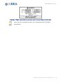
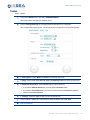
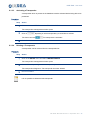
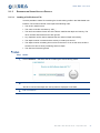
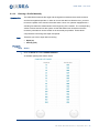
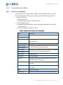
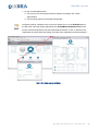
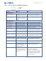
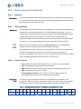
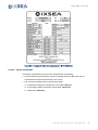
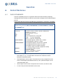
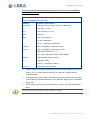
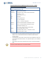
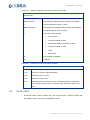
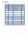
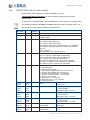
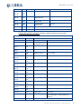
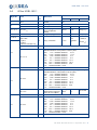
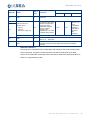
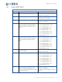
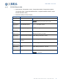
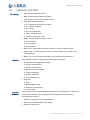
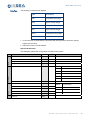
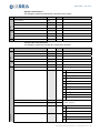
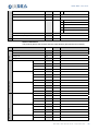
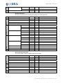
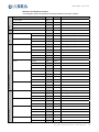
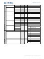
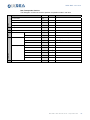
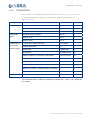
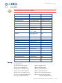
USBL-BOX – User Guide
A.4
HIPAP HPR 418 (fix and mobile)
Please refer to the Kongberg document HPR418BCD_revC.doc.
Transponder position message: the frame contains 32 bytes in binary format.
Example data:
X=1234.56m Y=-987.65m Depth 1234.5m Heading 59.9° Pos. to ROV 15. Training mode
The difference between the mobile and fixed protocols is made in the Byte 3 Bit 5. The
bit is equal to 1 in the mobile case and 0 in the fixed case.
Message
Example
Byte 0
0xDF
DF
Start of message
Byte 1
0x01
Head byte
1- SSBL position
Byte 2
0xSS
Status Byte 1
Bit 0: Position Measurement OK
Bit 1: Position measurement filtered
Bit 2: Position measurement predicted (always 0 for USBL-BOX)
Bit 3: Optional data SSBL OK (pressure sensor only for USBLBOX TP)
Bit 4-6: Always 0
Bit 7: Transceiver error (opposite of Bit 0)
Byte 3
0x20
Status Byte 2
Bit 0-1: Transducer number (MSB s/n USBL-BOX)
Bit 2-3: Transceiver number (LSB s/n USBL-BOX)
Bit 4: Training mode (always 0 for USBL-BOX)
Bit 5: Mobil TP (SSBL) Rov TP (LBL) (0 fixed, 1 mobile)
Bit 6: LBL co-ordinates in UTM (always 0 for USBL-BOX)
Bit 7: Master 0, Slave 1 (always 0 for USBL-BOX)
Byte 4
0x01
TP. Inf.
0 - TP (Transponder)
1 - Depth TP Optional Data 1
2 - Inclinometer TP Optional Data 1&2 /* not used here
3 - Diff.in.TP Optional Data 1&2 /*not used here
4 - Compass TP Optional Data 1 /* not used here
5 - Acoustic control transponder /* not used here
6 - Beacon /* not used here
7 - Depth Beacon /* not used here
10 -Responder driver 1 /* not used here
13 - Responder driver 4
Byte 5
Byte 6
0x00
0xTT
TP ID
Byte 7
Byte 8
Byte 9
0xsY
0xYY
0xYY
Y position
s = 0 if Y positive (Y HIPAP)
s = D if Y negative
BCD coded, LSB = 1/10 of unit
Byte 10
Byte 11
Byte 12
0xsX
0xXX
0xXX
X position
s = 0 if X positive (X HIPAP)
s = D if X negative
BCD coded, LSB = 1/10 of unit
Byte 13
Byte 14
Byte 15
0xsZ
0xZZ
0xZZ
Z position
s = 0 if Z positive
s = D if Z negative
BCD coded, LSB = 1/10 of unit
Byte 16
Byte 17
0xHH
0xHH
Heading LSB
Heading MSB
0° to 359.9° LSB=0.1°
BCD coded
Byte 18
Byte 19
XsD
0xDD
Sensor Depth
Optional Data 1
Meters
S=0
From 0 to 99
MU–USBL-BOX–AN–001 Ed. B – September 2011 69
USBL-BOX – User Guide
Byte 20
0xDD
BCD coded
Byte 21
Byte 22
Byte 23
0x00
0x00
0x00
Optional Data 2
Always 0
Byte 24
Byte 25
0x00
0x00
Horizontal error
Ellipse direction
Always 0
Byte 26
Byte 27
0x00
0x00
Horizontal error
Ellipse major
Always 0
Byte 28
Byte 29
0x00
0x00
Horizontal error
Ellipse minor
Always 0
Byte 30
0xXX
XX
Checksum
Byte 31
0xFF
FF
End of frame
Transponder position message: the frame contains 32 bytes in binary format.
Message
Byte 0
0xDF
Start of message
Byte 1
0x03
Head byte
TP sequence Telegram
Byte 2
0xSS
Number of
transponder in use
From 1 to 13
Byte 3
Byte 4
0xTT
0xTT
Number of TP 1
From 1 to 999
Byte 5
Byte 6
0xTT
0xTT
Number of TP 2
From 1 to 999
Byte 7
Byte 8
0xTT
0xTT
Number of TP 3
From 1 to 999
Byte 9
Byte 10
0xTT
0xTT
Number of TP 4
From 1 to 999
Byte 11
Byte 12
0xTT
0xTT
Number of TP 5
From 1 to 999
Byte 13
Byte 14
0xTT
0xTT
Number of TP 6
From 1 to 999
Byte 15
Byte 16
0xTT
0xTT
Number of TP 7
From 1 to 999
Byte 17
Byte 18
0xTT
0xTT
Number of TP 8
From 1 to 999
Byte 19
Byte 20
0xTT
0xTT
Number of TP 9
From 1 to 999
Byte 21
Byte 22
0xTT
0xTT
Number of TP 10
From 1 to 999
Byte 23
Byte 24
0xTT
0xTT
Number of TP 11
From 1 to 999
Byte 25
Byte 26
0xTT
0xTT
Number of TP 12
From 1 to 999
Byte 27
Byte 28
0xTT
0xTT
Number of TP 13
From 1 to 999
Byte 29
0x00
Dummy byte
Filled with 0
Byte 30
0xXX
Checksum
Bytes OR exclusive (except Checksum and
End of frame). Bit 7 of the Checksum is
always 0.
Byte 31
0xFF
End of frame
MU–USBL-BOX–AN–001 Ed. B – September 2011
70
USBL-BOX – User Guide
A.5
iXSea USBL INS 1
Nb of
Value
Byte Nb
Field
1
GGhex
8
header
55hex
Bits 2 to 0
3
Message number
001bin
Bits 7 to 3
5
Transponder ID
NA
180/2
- 90 °
90x(1-232) °
2
bits
Definition
LSB
Min
0
Max
31
3, 4, 5, 6
LLLLLLLLhex
32
Latitude (deg)
(Two-complement
coded)
7, 8, 9, 10
NNNNNNNNhex
32
Longitude (deg)
360/232
0°
360.(1-232) °
ZZZZZhex
(8+8+4 bits:
- byte11,
- byte12,
- bits 3 to 0 dof byte 13)
20
Z (m), immersion
0,01 m
0m
(00000hex
)
+10485,75
m
(FFFFFhex)
Bit 4
1
Reserved
Bits 7 to 5
3
Major axe XY: long axe (in m) of the error ellipse representing the
standard deviation on the position in the XY plane
000:
0 m < standard deviation <
0,5 m
001:
0,5 m < standard deviation <
1,5 m
010:
1,5 m < standard deviation <
3m
011:
3 m < standard deviation <
6m
100:
6 m < standard deviation < 12 m
101: 12 m < standard deviation < 25 m
110: 25 m < standard deviation < 50 m
111: standard deviation > 50 m
Bit 0
1
Reserved
Bits 3 to 1
3
Minor axe XY: small axe (in m) of the error ellipse representing the
standard deviation of the position in the XY plane
000:
0 m < standard deviation <
0,5 m
001:
0,5 m < standard deviation <
1,5 m
010:
1,5 m < standard deviation <
3m
011:
3 m < standard deviation <
6m
100:
6 m < standard deviation < 12 m
101: 12 m < standard deviation < 25 m
110: 25 m < standard deviation < 50 m
111: standard deviation > 50 m
Bits 7 to 4
4
Angle between the
North and the major axe
of the XY error ellipse l
Bit 0
1
Reserved
Bits 3 to 1
3
Standard deviation of the Z(m) position
000:
0 m < standard deviation <
0,5 m
001:
0,5 m < standard deviation <
1,5 m
010:
1,5 m < standard deviation <
3m
011:
3 m < standard deviation <
6m
100:
6 m < standard deviation < 12 m
101: 12 m < standard deviation < 25 m
110: 25 m < standard deviation < 50 m
111: standard deviation > 50 m
Bits 7 to 4
4
Reserved
11 to 12
13
14
15
32
180/24
0°
15/16 x180
°
MU–USBL-BOX–AN–001 Ed. B – September 2011 71
USBL-BOX – User Guide
Byte Nb
Field
16
PPhex
Nb of
bits
Value
Definition
LSB
Min
Max
0 ms
(3 599 999
ms, i.e. 1h 1ms
The largest
values of
this field do
not have
any
meaning
8
Reserved
rrrrrrrrrrrrrrrrrrrrrrbin
(8+8+6 bits of:
- byte 17,
- byte 18,
- bits 5 to 0 of byte 19)
22
It is the truncation of the
absolute time provided
by the GPS to the
USBL-BOX, keeping
only the minutes,
seconds, and
milliseconds. It is coded
in milliseconds number.
Bits 7 and 6 of byte19
2
Reserved
20
KKhex
8
Status byte
Bits 0 to 8 - Reserved
21
SShex
8
Checksum
exclusive OR by byte for the whole 20 first bytes thus header
included.
17, 18
19
1 ms
Immersion definition
The immersion corresponds to the mobile depth with respect to the mean sea level (thus
heave corrected). This data is coherent with the one that would be given by a depth
sensor on the underwater mobile. But it does not allow to deduce the absolute position as
there is no compensation for tide.
MU–USBL-BOX–AN–001 Ed. B – September 2011
72
USBL-BOX – User Guide
A.6
iXSea USBL INS 2
Message
$PXUI2,id,lat,lon,imm,maj,min,ang,dev,tim*CK
Field 1
Transponder ID
Field 2
Latitude (deg)
Resolution: 180/232
Domain: [-90 .. 90 x (1-232)]
Field 3
longitude (deg)
Resolution: 360/232
Domain: [-90 .. 360 x (1-232)]
Field 4
Immersion (m)
Resolution: 0,01 m
Domain: [0 .. +10485,75]
Field 5
Major axe XY (m)
0: 0 m < standard deviation < 0,5 m
Long axe of the error ellipse representing the
1: 0,5 m < standard deviation < 1,5 m
standard deviation on the position in the XY
2: 1,5 m < standard deviation < 3 m
plane
3: 3 m < standard deviation < 6 m
4: 6 m < standard deviation < 12 m
5: 12 m < standard deviation < 25 m
6: 25 m < standard deviation < 50 m
7: standard deviation > 50 m
Field 6
Minor axe XY (m)
0: 0 m < standard deviation < 0,5 m
Small axe of the error ellipse representing the
1: 0,5 m < standard deviation < 1,5 m
standard deviation of the position in the XY
2: 1,5 m < standard deviation < 3 m
plane
3: 3 m < standard deviation < 6 m
4: 6 m < standard deviation < 12 m
5: 12 m < standard deviation < 25 m
6: 25 m < standard deviation < 50 m
7: standard deviation > 50 m
Field 7
Field 8
Angle between the North and the major axe of
Resolution: 180/24
the XY error ellipse
Domain: [0 .. 15/16 x 180]
Standard deviation of the Z(m) position
0: 0 m < standard deviation < 0,5 m
1: 0,5 m < standard deviation < 1,5 m
2: 1,5 m < standard deviation < 3 m
3: 3 m < standard deviation < 6 m
4: 6 m < standard deviation < 12 m
5: 12 m < standard deviation < 25 m
6: 25 m < standard deviation < 50 m
7: standard deviation > 50 m
Field 9
Truncation of the absolute time provided by the
Resolution: 1ms
GPS to the USBL-BOX, keeping only the
Domain: [0 .. 3 599 999]
minutes, seconds, and milliseconds. It is coded
in milliseconds number.
The largest values of this field do not have any
meaning
MU–USBL-BOX–AN–001 Ed. B – September 2011 73
USBL-BOX – User Guide
Immersion definition
The immersion corresponds to the mobile depth with respect to the mean sea level (thus
heave corrected). This data is coherent with the one that would be given by a depth
sensor on the underwater mobile. But it does not allow to deduce the absolute position as
there is no compensation for tide.
Immersion
=
Measured depth (by the USBL acoustic array)
-
Heave
+
USBL immersion
MU–USBL-BOX–AN–001 Ed. B – September 2011
74
USBL-BOX – User Guide
A.7
NAUTRONIX ATS II
Message
Date Time B: Transp E: Status X: PosX Y: PosY D: psoZ H:
Heading P: pitch R: roll <CR><LF>
Field 1
Date
dd month AAAA
Field 2
Time
HH:MM:SS:mmm
Field 3
Transponder number
From 1 to 127
Field 4
Status
0
Field 5
X coordinate
In meters (‘+’ when directed to starboard)
Field 6
Y coordinate
In meters (‘+’ when directed to the bow)
Field 7
Z coordinate
In meters (‘+’ when directed to the bottom)
Field 8
Heading
In degrees (‘+’ clockwise)
Field 9
Pitch
In degrees (‘+’ when bow up)
Field 10
Roll
In degrees (‘+’ when starboard up)
MU–USBL-BOX–AN–001 Ed. B – September 2011 75
USBL-BOX – User Guide
A.8
POSIDONIA 6000
• Data received: Transponder number, Transponder latitude, Transponder longitude,
Transponder depth, Latitude standard deviation, Longitude standard deviation, Depth
standard deviation, Delay
• Data frame: Binary format (32 bytes)
Message
<Sync><F1><F2>…..<F8><Ch1Ch2>
Byte 0
0x24
Synchronization byte
Data Field 1
Transponder number
Warning: The first received number is used as a
synchronization byte for all the other inputs
Byte 1
Data Field 2
Transponder latitude
+/-232 = +/-Pi signed 32 bits
Transponder longitude
+/-232 = +/-Pi signed 32 bits
Transponder depth
IEEE floating point format , meters
Bytes 2 to 5
Data Field 3
Bytes 6 to 9
Data Field 4
Warning: Not used by the INS
Bytes 10 to 11
Data Field 5
Latitude standard deviation IEEE floating point format , meters
Bytes 12 to 17
Data Field 6
Longitude standard
Bytes 18 to 21
deviation
Data Field 7
Depth standard deviation
IEEE floating point format , meters
Delay
IEEE floating point format , seconds
Checksum
Addition of all the bytes from 0 to 29.
IEEE floating point format , meters
Bytes 22 to 25
Data Field 8
Bytes 26 to 29
Bytes 30 to 31
Warning: 2 characters
MU–USBL-BOX–AN–001 Ed. B – September 2011
76
USBL-BOX – User Guide
A.9
USBLBOX_POSTPRO
Terminology
• CRP: Common Reference Point
• BRD: Acoustic Antenna Mounting Flange
• CAC: Acoustic center of the acoustic antenna
• RIXI: iXSea Reference Frame
‰
X+: towards the bow (axis of the ship)
‰
Y+: towards starboard
‰
Z+: upward
‰
Roll+: port goes down
‰
Pitch+: bow goes down
‰
Heading+: Bow goes to port.
• RANT: Acoustic antenna reference frame
‰
X+ towards H1
‰
Y+ towards H4
‰
Z+ downwards
• RIXI o CRP : iXSea reference frame centered on common reference point
• RANT o BRD : Acoustic antenna reference frame centered on the center of the
mounting flange
• RANT o Hx : Acoustic antenna reference frame centered on hydrophone x
Overview
USBL REJEU protocol comprises all necessary data for payback:
• Configuration data (supposed invariant)
‰
System characteristics
‰
Beacon characteristics
• Operational environment data
‰
Antenna calibration
‰
System Installation
‰
Sound speed profile
• Input data
Protocol
Structure
‰
Time
‰
Raw navigation data
‰
Detection characteristics
‰
Ancillary data
The protocol comprises binary datagrams produced by the equipment. It contains the
sufficient and necessary data for playback of the applied real time processing.
The datagrams comprise :
• Header for identification and characterization
• Main body of data described in the header
• Checksum (bytes sum)
MU–USBL-BOX–AN–001 Ed. B – September 2011 77
USBL-BOX – User Guide
Data Type
The following conventions are applied:
Type
Description
byte
Unsigned 8 bits integer
short
Signed 16 bits Integer
ushort
Unsigned 16 bits Integer
long
Signed 32 bits Integer
ulong
Unsigned 32 bits Integer
float
Float IEEE 754 32 bits
• 16 and 32 bytes encoded data are described with the Big endian convention (strong
weight byte sent first)
• NaN have a value of Ox7FC00000
System Identification
Version
Identification
Header
This datagram gathers the configuration elements of the system.
Description
Format
Synchronization
byte
'$'
Total Size
byte
30
Datagram ID
byte
$80
Datagram release number
byte
$01
Equipment Type
ushort
0
Inconnu
1
GAPS - TITAN – CL
2
GAPS - CARBON – ML
3
GAPS - TITAN – ML
4
(U-BOX) - FLUSH
5
(U-BOX) - CAGE
Serial Number
ushort
FPGA DSP
ulong
Firmware DSP
ulong
FPGA Mother board
ulong
Firmware Mother board
ulong
Algorithms
ulong
Checksum
ushort
Unit
Observation
MMSB
implementation
MSB
major release
LSB
minor release
LLSB
correction
MU–USBL-BOX–AN–001 Ed. B – September 2011
78
USBL-BOX – User Guide
System Characteristics
Parameters
Header
This datagram gathers the identification elements of the system.
Description
Format
Unit
Observation
Synchronization
byte
'$'
Total Size
byte
16
Datagram ID
byte
$81
Datagram release number
byte
$01
Demodulation frequency
float
Hertz
Maximum phase error
float
radian
Maximum phase jumps
short
Checksum
ushort
`
Transponders Characteristics
Transponder
Ctrl
Header
This datagram gathers the transponder configuration elements.
Description
Format
Unit
Observation
Synchronization
byte
'$'
Total Size
byte
35
Datagram ID
byte
$82
Datagram release number
byte
$01
Transponder number
short
Positif, Base 0
Total number of transponder
short
Positif, max 50
Transponder ID
short
Transponder type
short
-1
Générique
0
RT8
1
Monotonal
2
RT9
MF
3
MT9
MF
4
BT8
MF
5
RT9
BF
6
RAMSES 6000
7
ET9
8
RTT4
9
RT8
MF
MF
BF
BF
BF
Code / interrogation frequency
ushort
- / Hz
< 8000 : code MFSK
Code / response frequency
ushort
- / Hz
>= 8000 : frequency
Operational behavior
byte
Interrogation mode
byte
BF
0
None
1
Fixed transponder
2
Mobile transponder
0
Transponder
1
Primary responder
2
Spontaneous (pinger)
MU–USBL-BOX–AN–001 Ed. B – September 2011 79
USBL-BOX – User Guide
Turn around time
short
ms
Reply signal
float
Hertz
Depth management
byte
Accuracy of the configuration depth
float
meter
Accuracy of the depth by pressure measurement
float
meter
Checksum
ushort
3
Secondary Responder
0
No known depth
1
Pressure sensor
2
Not used
3
Acoustic telemetry
4
Configuration depth
Antenna Calibration
Header
This protocol gathers the acoustic antenna characteristics (theoretical and measured)
Description
Format
Synchronization
byte
'$'
Total Size
byte
102
Datagram ID
byte
$83
Datagram release number
byte
$01
Pair H1 / H2
Theoretical antenna
Pair H2 / H3
Pair H3 / H4
Pair H1 / H2
Measured antenna
Pair H2 / H3
Pair H3 / H4
Unit
Observation
Delta X
float
meter
RANT o H1
Delta Y
float
meter
RANT o H1
Delta Z
float
meter
RANT o H1
Delta Phase
float
radian
Delta X
float
meter
RANT o H2
Delta Y
float
meter
RANT o H2
Delta Z
float
meter
RANT o H2
Delta Phase
float
radian
Delta X
float
meter
RANT o H3
Delta Y
float
meter
RANT o H3
Delta Z
float
meter
RANT o H3
Delta Phase
float
radian
Delta X
float
meter
RANT o H1
Delta Y
float
meter
RANT o H1
Delta Z
float
meter
RANT o H1
Delta Phase
float
radian
Delta X
float
meter
RANT o H2
Delta Y
float
meter
RANT o H2
Delta Z
float
meter
RANT o H2
Delta Phase
float
radian
Delta X
float
meter
RANT o H3
Delta Y
float
meter
RANT o H3
MU–USBL-BOX–AN–001 Ed. B – September 2011
80
USBL-BOX – User Guide
Delta Z
float
meter
Delta Phase
float
radian
Checksum
RANT o H3
ushort
System Installation
Header
This protocol gathers all the elements describing the system geometry.
Description
Format
Synchronization
byte
'$'
Total Size
byte
62
Datagram ID
byte
$84
Datagram release number
byte
$01
Misalignments
Attitude sensor
Observation
Delta Heading
float
degree
RIXI
Delta Roll
float
degree
RIXI
Delta Pitch
float
degree
RIXI
Delta Heading
float
degree
RIXI
Delta Roll
float
degree
RIXI
Delta Pitch
float
degree
RIXI
Delta X
float
meter
RIXI o CRP
Delta Y
float
meter
RIXI o CRP
Delta Z
float
meter
RIXI o CRP
Delta X
float
meter
RIXI o CRP
Delta Y
float
meter
RIXI o CRP
Delta Z
float
meter
RIXI o CRP
Sea Level
Delta Z
float
meter
RIXI o CRP
Acoustic center
Delta Z
float
meter
RANT o BRD
Mounting flange
Position sensor
Mounting Flange
Offsets
Unit
Checksum
ushort
Sound Velocity Profile Pair
Pair
Ctrl
Header
The sound velocity profile comprises depth/velocity pairs.
Description
Format
Unit
Observation
Synchronization
byte
'$'
Total Size
byte
18
Datagram ID
byte
$85
Datagram release number
byte
$01
Pair number
short
>0, Base 0
Total number of pairs
short
>0, Maximum 55
Depth
float
meter
>0
Velocity
float
m/s
between 1400 and 1600
Checksum
ushort
MU–USBL-BOX–AN–001 Ed. B – September 2011 81
USBL-BOX – User Guide
Detection and detection context
Header
This datagram gathers all elements describing detections and their contexts.
Description
Format
Synchronization
byte
'$'
Total Size
byte
219
Datagram ID
byte
$86
Datagram release number
byte
$01
Transponder ID
short
Interrogation
Time
Detection
Position
Position accuracy
Attitude
Interrogation raw position
Attitude accuracy
Speed
Position
Position accuracy
Detection raw position
Attitude
Attitude accuracy
Unit
Observation
Seconds
ulong
s
Base 01/01/1970 (time_t)
Micro seconds
ulong
μs
Seconds
ulong
s
Micro seconds
ulong
μs
Latitude
long
[-2 ..+2 ] ≡ [-180..+180]
Longitude
long
[-2 ..+2 ] ≡ [-180..+180]
Altitude
float
meter
Latitude
float
meter
Longitude
float
meter
Altitude
float
meter
Heading
float
degree
Roll
float
degree
Pitch
float
degree
Heave
float
meter
Heading
float
degree
Roll
float
degree
Pitch
float
degree
Heave
float
meter
North
float
m/s
East
float
m/s
Vertical
float
m/s
Latitude
long
[-2 ..+2 ] ≡ [-180..+180]
Longitude
long
[-2 ..+2 ] ≡ [-180..+180]
Altitude
float
meter
Latitude
float
meter
Longitude
float
meter
Altitude
float
meter
Heading
float
degree
Roll
float
degree
Pitch
float
degree
Heave
float
meter
Heading
float
degree
Roll
float
degree
Base 01/01/1970 (time_t)
31
31
31
31
31
31
31
31
MU–USBL-BOX–AN–001 Ed. B – September 2011
82
USBL-BOX – User Guide
Speed
Arrival time
Phase
Auxiliary data
Acoustic detection (49)
Noise Signal Ratio
Validity
Pitch
float
degree
Heave
float
meter
North
float
m/s
East
float
m/s
Vertical
float
m/s
H1
float
S
interrogation
H2
float
S
interrogation
H3
float
S
interrogation
H4
float
s
interrogation
H1
float
radian
H2
float
radian
H3
float
radian
H4
float
radian
H1
float
dB
H2
float
dB
H3
float
dB
H4
float
dB
H1
byte
Bit 0
[0,1] ≡ [invalid, valid]
H2
Bit 1
[0,1] ≡ [invalid, valid]
H3
Bit 2
[0,1] ≡ [invalid, valid]
H4
Bit 3
[0,1] ≡ [invalid, valid]
0
Invalid known position
1
Pressure sensor
2
Not used
3
Acoustic telemetry
4
Configuration depth
0
Unknown CAC Velocity
1
Speed profile
2
Temperature data
Known depth
float
Origin of known depth
byte
Known CAC velocity
float
Origin of the known CAC velocity
byte
Checksum
meter
m/s
ushort
MU–USBL-BOX–AN–001 Ed. B – September 2011 83
USBL-BOX – User Guide
Raw Transponder Position
Header
This datagram contains the result of position computation made in real time.
Description
Format
Synchronization
byte
'$'
Total Size
byte
56
Datagram ID
byte
$87
Datagram release number
byte
$01
Transponder ID
short
Age de la position
ulong
μs
Since emission
Seconds
ulong
s
Base 01/01/1970 (time_t)
Micro seconds
ulong
μs
Latitude
long
[-2 ..+2 ] ≡ [-180..+180]
Longitude
long
[-2 ..+2 ] ≡ [-180..+180]
Immersion
float
Time
Emission
Position
Transponder
Covariance position
Checksum
Unit
Observation
meter
31
31
31
31
Not tide corrected
2
North / North
float
meter
North / East
float
meter
North / Depth
float
meter
East / East
float
meter
East / Depth
float
meter
Depth / Depth
float
meter
2
2
2
2
2
ushort
MU–USBL-BOX–AN–001 Ed. B – September 2011
84
USBL-BOX – User Guide
A.10
PIFM-POPSN
$PIFM,POPSN,JJ/MM/AAAA,HH:MM:SS,DDD,ddd.dd,±vv.vv,±vv.vv,CCCC,nn,
JJ/MM/AAAA,HH:MM:SS.DDD,s,dd,mm.mmmm,s,ddd,mm.mmmm,mmmm,c,c,
mmmm,[CR][LF]
Message
Format
Bytes
ID
$PIFM,POPSN,
12
Date
JJ/MM/AAAA,
11
Time
HH:MM:SS,DDD,
13
Heading and
Heading (0 à 360), degrees
ddd.dd,
7
Speed
Speed X, knots
±vv.vv,
7
Speed Y, knots
±vv.vv,
7
Transponder or
Transponder or mobile device ID *
4 characters,
5
other Mobile
Transponder number
nn,
3
Position date
JJ/MM/AAAA,
11
Time position
HH:MM:SS.DDD,
13
Latitude in degrees, s is the sign of the latitude
s,dd,mm.mmmm,
13
Longitude in degrees, s is the sign of the longitude
s,ddd,mm.mmmm, 14
Depth, meters
mmmm,
5
Validity X, Y (F valid and 0 for invalid)
c,
2
Validity Z (0: invalid, 1: computed value, 2: measure)
c,
2
Depth sensor data, meters
mmmm,
5
End
[CR][LF]
2
Header
Device Position
Message End
* ID: transponder ID in 4 characters (example for transponder 1: « 0001 », for transponder
26: « 0026 »)
MU–USBL-BOX–AN–001 Ed. B – September 2011 85
USBL-BOX – User Guide
B.
INPUT PROTOCOLS
B.1
$xxGGA / $xxVTG
Data sent:
Latitude, Longitude of the ship or GAPS, GPS quality
$GPGGA,hhmmss.ss,ddmm.mmmmm,a,dddmm.mmmmm,b,q,ss,...,…,.,…,.,…,….*
hh<CR><LF>
B.2
hhmmss.ss
is the UTC of position
ddmm.mmmmm
is the latitude in degrees and in minutes and 1/100000
a
is the hemisphere N: North S: South
dddmm.mmmmm
is the longitude in degrees and in minutes and 1/100000
b
is longitude sign (E: East, W: West)
q
is the GPS quality indicator
•
0 Fix not valid
•
1 GPS SPS Mode fix valid
•
2 Differential Mode, SPS Mode, fix valid
•
3 GPS PPS Mode, fix valid
•
4 RTK
•
5 Float RTK
ss
is the number of satellites
*hh
is optional
$xxZDA
Data received: the Universal Time information
$GPZDA,hhmmss.ss,dd,mm,yyyy,xx,yy*cc<CR><LF>
B.3
hhmmss.ss
is the UTC time in hours, minutes, seconds of the GPS position
dd
is the day dd = 0 to 31
mm
is the month mm =1 to 12
yyyy
is the year
xx
is the local zone description in hours xx = -13 to 13
yy
is the local zone description in minutes yy = 0 to 59
*cc
is the checksum
$ZQMTE
$GPZDA, jj/mm/aa,hh : mm : ss.s
Function
Hour
Field1
Date
Day, Month, Year
Field 2
Time
Hour, Minute, Seconds and tenths of seconds
MU–USBL-BOX–AN–001 Ed. B – September 2011
86
USBL-BOX – User Guide
B.4
SIMRAD EM
THIS PROTOCOL MUST HAVE A RATE OF 20 HZ.
•
Standard:
SIMRAD owned format
•
Data sent
Heading, Roll, Pitch, Heave and status
10 bytes binary data protocol
Message
SS 90 RRRR PPPP hhhh HHHH
octet 0
0xSS
octet Sync
Sensor status
octet 1
0x90
Sync octet
octet 2
0xRRRR
Roll LSB
octet 3
octet 4
Roll MSB
0xPPPP
octet 5
octet 6
Pitch MSB
0xhhhh
octet 7
octet 8
octet 9
Pitch LSB
Heave LSB
Heave MSB
0xHHHH
Cap LSB
Cap MSB
0x90 ⇒ OK
0x9A ⇒ alignment
Roll ± 180°
LSB : 0.01°
Signe “+” when port goes up
Pitch ± 180°
LSB : 0.01°
Signe “+” when stern goes up
Heave ± 10 m
LSB : 0.01 m
Signe “+” when OCTANS goes up
Cap 0° to 360°
LSB : 0.01°
MU–USBL-BOX–AN–001 Ed. B – September 2011 87
USBL-BOX – User Guide
B.5
GAPSBIN
THIS PROTOCOL MUST HAVE A RATE OF 20 HZ.
Data
Format
Units
Header
8 bit unsigned integer
Value : ‘$’
Time tag of data
64 bit unsigned integer
See Note 1
INS interface status 1
32 bit unsigned integer
See [M-SP-POP-099]
INS algorithm status 2
32 bit unsigned integer
See [M-SP-POP-099]
Heading
32 bit IEEE Float
Rad
Roll
32 bit IEEE Float
Rad
Pitch
32 bit IEEE Float
Rad
Latitude
32 bit signed integer
Rad
+/- 231= +/-Pi/2
Longitude
32 bit signed integer
Rad
31
+/- 2 = +/-Pi
Time Tag
Altitude (positive up)
32 bit IEEE Float
m
North speed
32 bit IEEE Float
m/s
West speed
32 bit IEEE Float
m/s
Vertical speed (positive up)
32 bit IEEE Float
m/s
Heave on selected lever arm
32 bit IEEE Float
m
Latitude standard deviation
32 bit IEEE Float
rad
Longitude standard deviation
32 bit IEEE Float
rad
Altitude standard deviation
32 bit IEEE Float
m
Heading standard deviation
32 bit IEEE Float
Rad
Roll standard deviation
32 bit IEEE Float
Rad
Pitch standard deviation
32 bit IEEE Float
Rad
CRC
16 bit unsigned integer
Fin de trame
8 bit unsigned integer
Valeur : ‘#’
The 64 bits time tag is described hereafter:
Bit [63..56] spare
Bit [55..52] x 10 days (0 à 3)
Bit [51..48] days (0 à 9)
Bit [47..44] x 10 hour (0 à 2)
Bit [43..40] hours (0 à 9)
Bit [39..35] x 10 minutes (0 à 5)
Bit [34..31] minutes (0 à 9)
Bit [31..28] x 10 seconds (0 à 5)
Bit [27..24] seconds (0 à 9)
Bit [23..20] x 1/10 seconds (0 à 9)
Bit [19..16] x 1/100 seconds (0 à 9)
Bit [15..12] x 1000 µseconds (0 à 9)
Bit [11..8] x 100 µseconds (0 à 9)
Bit [7..4] x 10 µseconds (0 à 9)
Bit [3..0] µseconds (0 à 9)
MU–USBL-BOX–AN–001 Ed. B – September 2011
88
USBL-BOX – User Guide
B.6
$PMEVL
Data received: Pressure value
$PMEVL,XP,MEA,C,VVVVV*cc<CR><LF>
XP
is the transponder ID (from 001 up o 128)
MEA
is a mnemonic
C
is the analog channel, C = 8
VVVVV
is the Pressure value
VVVVV = 0 to 65535 dBars (integer)
*cc
or VVVV.V = 0.0 to 9999.9 dbars (float)
is the checksum
B.7
$WIMTW
This protocol is used to know the water temperature at the face of the antenna.
$WIMTW,x.y,C*xx
x, y
Temperature en Celsius degrees
The C is mandatory and means Celsius
MU–USBL-BOX–AN–001 Ed. B – September 2011 89
USBL-BOX – User Guide
C.
CHOOSING AN IP ADDRESS AND A SUBNET MASK
You need to change the configuration, you need to provide two IP (Internet Protocol)
addresses for both the USBL-BOX and the PC. Keep track of the addresses entered on
both systems, as they are different. You need to setup a private network between the PC
and the USBL-BOX, you need to select an address for the PC and the USBL-BOX.
For example, in private network addresses, it is usually recommended to use addresses of
• Either Class B (169.254.0.0 to 169.254.255.255) – Subnet Mask: 255.255.0.0
• Or Class C (192.168.0.0 to 192.168.0.255) – Subnet Mask: 255.255.255.0
For Class C, the first (e.g. 192.168.0.0) and last (e.g. 192.168.0.255) addresses are
reserved and therefore they cannot be used.
It is recommended to select two addresses from the same range set. For example:
• Either 169.254.0.1 for USBL-BOX and 169.254.0.2 for the PC (Subnet 255.255.0.0)
• Or 192.168.1.10 for USBL-BOX and 192,168.1.11 for the PC (Subnet 255.255.255.0)
MU–USBL-BOX–AN–001 Ed. B – September 2011
90
USBL-BOX – User Guide
D.
WIRING OF THE POSIDONIA ANTENNA
First column: Definition of the connection point on the connector
Second column: Description of the function of the transmitted signal
Third column: Definition of the connection point on the board REAR FACE of the rack
(except for the two wires dedicated to transmission that are directly connected to the HT
board)
Pin
Function
Connected to
A
Power Supply +12V
J15 pin 3
B
Ground +12V (GND B)
J15 pin 4
D
Gain+
J35 pin 1
G
Gain-
J35 pins 2, 3, 4, 5
H
Gain-
J35 pins 2, 3, 4, 5
K
Channel 1 +
J19 pin 1
L
Channel 1 -
J19 pins 2, 3, 4, 5
N
Channel 2 +
J22 pin 1
P
Channel 2 -
J22 pins 2, 3, 4, 5
S
Channel 3 +
J25 pin 1
T
Channel 3 -
J25 pins 2, 3, 4, 5
V
Channel 4 +
J32 pin 1
W
Channel 4 -
J32 pins 2, 3, 4, 5
b
Transmission HOT (brown)
Brown wire (direct HT)
c
Transmission COLD (yellow)
Yellow wire (direct HT)
e
Power supply -12V
J15 pin 1
f
Ground -12V (GND B)
J15 pin 2
p
Contact hydro +
J39 pin 1
q
Contact hydro -
J39 pins 2, 3, 4, 5
MU–USBL-BOX–AN–001 Ed. B – September 2011 91
USBL-BOX – User Guide
E.
MECHANICAL DRAWING
MU–USBL-BOX–AN–001 Ed. B – September 2011
92