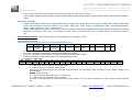
1
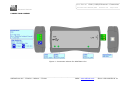
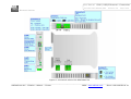
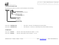
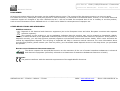
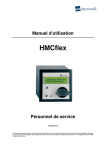
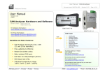
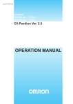
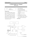
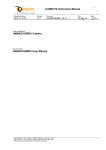
User Manual
CAN / USB/Ethernet - Converter
Document code: MN67390_ENG
Revision 1.005
Page 1 of 28
Electronic Devices
User Manual
Revision 1.005
English
CAN / USB – Converter, for CAN
Analysis use
(Order Code: HD67390-U-D1)
CAN / Ethernet – Converter, for
CAN Analysis use
HD67390-U-D1
(Order Code: HD67390-E-D1)
for Website information:
www.adfweb.com?Product=HD67390
for Price information:
www.adfweb.com?Price=HD67390-U-D1
www.adfweb.com?Price=HD67390-E-D1
Benefits and Main Features:
CAN Analyzer Advanced 2.0A, 2.0B
(11 and 29 bit identifier);
Free updating to lifetime;
HW filter for CAN packet;
MAX baud rate 1Mb;
Industrial temperature range
-40°C / 85°C (-40°F / 185°F)
HD67390-E-A1
For others similar products:
CAN Analyzer
See also the following link:
www.adfweb.com?Product=HD67316
Do you have an your customer protocol?
See the following links:
www.adfweb.com?Product=HD67003
Do you need to choose a device? do you want help?
Ask it to the following link:
www.adfweb.com?Cmd=helpme
______________________________________________________________________________________________________________
Phone +39.0438.30.91.31
ADFweb.com Srl – IT31010 – Mareno – Treviso
INFO: www.adfweb.com
User Manual
CAN / USB/Ethernet - Converter
Document code: MN67390_ENG
Revision 1.005
Page 2 of 28
Electronic Devices
UPDATED DOCUMENTATION:
INDEX:
Page
INDEX
UPDATED DOCUMENTATION
REVISION LIST
WARNING
TRADEMARKS
SECURITY ALERT
CONNECTION SCHEME
INTRODUCTION
POWER SUPPLY
USB
ETHERNET
LEDS
UPDATE NEW FIRMWARE
CAN
PROTOCOL
MECHANICAL DIMENSIONS
ORDERING INFORMATIONS
ACCESSORIES
DISCLAIMER
OTHER REGULATIONS AND STANDARDS
WARRANTIES AND TECHNICAL SUPPORT
RETURN POLICY
PRODUCTS AND RELATED DOCUMENTS
2
2
2
2
2
3
4
6
6
7
7
7
9
12
13
25
26
26
27
27
28
28
28
Dear customer, we thank you for your attention and we remind you that
you need to check that the following document is:
Updated
Related to the product you own
To obtain the most recently updated document, note the “document code”
that appears at the top right-hand corner of each page of this document.
With this “Document Code” go to web page www.adfweb.com/download/
and search for the corresponding code on the page. Click on the proper
“Document Code” and download the updates.
To obtain the updated documentation for the product that you own, note
the “Document Code” (Abbreviated DC on the product’s box) and
download the updated from our web site www.adfweb.com/download/
REVISION LIST:
Revision
1.002
1.003
1.004
1.005
Date
05/12/2011
10/04/2012
07/02/2013
30/05/2013
Author
Fl
Fl
Nt
Fl
Chapter
All
All
All
All
Description
Revision
Revision
Added new chapters
Added USB driver link
WARNING:
ADFweb.com reserves the right to change information in this manual
about our product without warning.
ADFweb.com is not responsible for any error this manual may contain.
TRADEMARKS:
All trademarks mentioned in this document belong to their respective
owners.
______________________________________________________________________________________________________________
Phone +39.0438.30.91.31
ADFweb.com Srl – IT31010 – Mareno – Treviso
INFO: www.adfweb.com
User Manual
CAN / USB/Ethernet - Converter
Document code: MN67390_ENG
Revision 1.005
Page 3 of 28
Electronic Devices
SECURITY ALERT:
GENERAL INFORMATION
To ensure safe operation, the device must be operated according to the instructions in the manual. When using the device are required for
each individual application, legal and safety regulation. The same applies also when using accessories.
INTENDED USE
Machines and systems must be designed so the faulty conditions do not lead to a dangerous situation for the operator (i.e. independent
limit switches, mechanical interlocks, etc.).
QUALIFIED PERSONNEL
The device can be used only by qualified personnel, strictly in accordance with the specifications.
Qualified personnel are persons who are familiar with the installation, assembly, commissioning and operation of this equipment and who
have appropriate qualifications for their job.
RESIDUAL RISKS
The device is state of the art and is safe. The instrument can represent a potential hazard if they are inappropriately installed and
operated by personnel untrained. These instructions refer to residual risks with the following symbol:
This symbol indicates that non-observance of the safety instructions is danger for people to serious injury or death and / or the
possibility of damage.
CE CONFORMITY
The declaration is made by us. You can send an email to [email protected] or give us a call if you need it.
______________________________________________________________________________________________________________
ADFweb.com Srl – IT31010 – Mareno – Treviso
INFO: www.adfweb.com
Phone +39.0438.30.91.31
User Manual
CAN / USB/Ethernet - Converter
Document code: MN67390_ENG
Revision 1.005
Page 4 of 28
Electronic Devices
CONNECTION SCHEME:
Figure 1: Connection scheme for HD67390-U-D1
______________________________________________________________________________________________________________
ADFweb.com Srl – IT31010 – Mareno – Treviso
INFO: www.adfweb.com
Phone +39.0438.30.91.31
User Manual
CAN / USB/Ethernet - Converter
Document code: MN67390_ENG
Revision 1.005
Page 5 of 28
Electronic Devices
Figure 2: Connection scheme for HD67390-E-A1
______________________________________________________________________________________________________________
ADFweb.com Srl – IT31010 – Mareno – Treviso
INFO: www.adfweb.com
Phone +39.0438.30.91.31
User Manual
CAN / USB/Ethernet - Converter
Document code: MN67390_ENG
Revision 1.005
Page 6 of 28
Electronic Devices
INTRODUCTION:
The CANbus from/to USB/Ethernet is a powerful, flexible and economic instrument for communicate through USB/Ethernet with systems
based in CAN/CANopen/J1939/DeviceNet/NMEA2000.
The instrument is composed of the following: module hardware with a USB/Ethernet interface that connects to a personal computer and a
CAN terminal that connects to the line.
The software must be created following the information in this document. For the USB version the Port used is a COM port; for the
Ethernet version you have to use the UDP protocol.
POWER SUPPLY:
The HD67390-U-D1 device don’t need an external power supply for work. The alimentation is given by USB port.
The HD67390-E-A1 can be powered at 8…19V AC and 8…35V DC. For more details see the two tables below.
VDC
VAC
Vmin
Vmax
Vmin
Vmax
8V
19V
8V
35V
Consumption at 24V DC:
Device
HD67390-E-A1
W/VA
3.5
Caution: Not reverse the polarity power
HD67390-E-A1
______________________________________________________________________________________________________________
ADFweb.com Srl – IT31010 – Mareno – Treviso
INFO: www.adfweb.com
Phone +39.0438.30.91.31
User Manual
CAN / USB/Ethernet - Converter
Document code: MN67390_ENG
Revision 1.005
Page 7 of 28
Electronic Devices
USB:
The USB connector (Connector1) of HD67390-U-D1 is a Type-B Female. So the cable must be a Type-B Male.
The driver of USB can be downloaded from here: www.adfweb.com/download/filefold/SW67119.zip.
ETHERNET:
The Ethernet connection must be made using Connector3 of HD67390-E-A1 with at least a Category 5E cable. The maximum length of the
cable should not exceed 100m. The cable has to conform to the T568 norms relative to connections in cat.5 up to 100 Mbps. To connect
the device to an Hub/Switch is recommended the use of a straight cable, to connect the device to a PC/PLC/other is recommended the use
of a cross cable.
LEDS:
The device HD67390-U-D1 has got three LEDs that are used to give information of the functioning status.
The various meanings of the LEDs are described in the table below.
LED
1: Device State
(Green)
Normal Mode
Blink slowly (∼2Hz)
Boot Mode
Blink quickly
Blink slowly: No frame is received
2: Receiving USB
(Blue)
Blink quickly
Blink quickly: Frame received on USB
Blink slowly: No frame is received
3: Receiving CAN
(Blue)
Blink quickly
Blink quickly: Frame received on CAN
______________________________________________________________________________________________________________
ADFweb.com Srl – IT31010 – Mareno – Treviso
INFO: www.adfweb.com
Phone +39.0438.30.91.31
User Manual
CAN / USB/Ethernet - Converter
Document code: MN67390_ENG
Revision 1.005
Page 8 of 28
Electronic Devices
The device HD67390-E-A1 has got four LEDs that are used to give information of the functioning status.
The various meanings of the LEDs are described in the table below.
LED
Normal Mode
Boot Mode
Blink slowly (∼
∼2Hz): No frame is received
1: Receiving CAN
(Green)
Blink quickly
Blink quickly: A frame is received
2: Transmitting CAN
3: Link Ethernet
4: Device State
(Green)
Blink slowly (∼2Hz)
Blink quickly
ON: Ethernet Cable connected
ON: Ethernet Cable connected
OFF: Ethernet Cable disconnected
OFF: Ethernet Cable disconnected
Blink slowly (∼2Hz)
Blink quickly
(Green)
(Green)
______________________________________________________________________________________________________________
ADFweb.com Srl – IT31010 – Mareno – Treviso
INFO: www.adfweb.com
Phone +39.0438.30.91.31
User Manual
CAN / USB/Ethernet - Converter
Document code: MN67390_ENG
Revision 1.005
Page 9 of 28
Electronic Devices
UPDATE NEW FIRMWARE:
ON HD67390-U-D1:
For update the firmware version of HD67390-U-D1 it is necessary to download from this link
www.adfweb.com/download/filefold/USB_SW67316_Update.zip the files that are necessary for
do the operation.
After extracting the archive you have to launch the executable “USB_SW67316_Update.exe”
file. The window that appears is shown in Fig. 3.
The steps to do are:
Connect the device to an USB port and press the “Update COMport List” button;
Select the COM port where the device is attached (USB port is virtualized like a serial);
Press the “Update Device” button and select the file “FW_USB_SW67316.sim”.
When in the log field appears this “Update made with success” sentence the updating is
finished correctly.
If doesn’t appears, try to repeat the operations.
Figure 3: HD67316 CAN Analyzer USB
Firmware Update
______________________________________________________________________________________________________________
ADFweb.com Srl – IT31010 – Mareno – Treviso
INFO: www.adfweb.com
Phone +39.0438.30.91.31
User Manual
CAN / USB/Ethernet - Converter
Document code: MN67390_ENG
Revision 1.005
Page 10 of 28
Electronic Devices
ON HD67390-E-A1:
For update the firmware version or changing the Ethernet parameters of HD673190-E-A1 it is necessary to download from this link
www.adfweb.com/download/filefold/SW67216.zip the files that are necessary for do the operation.
You have to install the SW67216 program,
launch it (Fig.4 appears) and follow these
instructions:
Connect the Ethernet cable to the
Analyzer and feed it;
Go to “Function” “SetPort”, select
“Ethernet Type (HD67316-E-A1)” and
press the “OK” button;
Go to “Ethernet” “Configuration” and
select or “By Serial” if you don’t know the
settings of Ethernet parameters; or “By
Ethernet” if you know the IP Address and
the Port.
Figure 4: Main window of SW67216
USE OF “BY SERIAL”
The window (Fig. 5) is divided in two sections, one for the data of Ethernet and the other for the actual
update.
The parameters that are necessary to set are: “IP Address”, “SubNet Mask”, “Default Gateway”,
“Port”.
After selecting the correct COM port you have to select the operations you want to do. You can select
only “Firmware”, only “Project” or both of them. Then press the “UPDATE” button.
When appears Fig. 6 the update will be completed with
success.
Figure 5: Update “By Serial” window
Figure 6: “Update Device” window
______________________________________________________________________________________________________________
ADFweb.com Srl – IT31010 – Mareno – Treviso
INFO: www.adfweb.com
Phone +39.0438.30.91.31
User Manual
CAN / USB/Ethernet - Converter
Document code: MN67390_ENG
Revision 1.005
Page 11 of 28
Electronic Devices
USE OF “BY ETHERNET”
The window (Fig. 7) is divided in two sections, one for the data of Ethernet and the other for the actual
update.
The parameters that are necessary to set are: “IP Address”, “SubNet Mask”, “Default Gateway”,
“Port”.
After inserting the actual “IP Address” and the actual “Port” you have to select the operations you
want to do. You can select only “Firmware”, only “Project” or both of them. Then press the
“UPDATE” button.
When appears Fig. 8 the update will be completed with success.
Figure 8: “Update Device” window
Figure 7: Update “By Ethernet” window
______________________________________________________________________________________________________________
ADFweb.com Srl – IT31010 – Mareno – Treviso
INFO: www.adfweb.com
Phone +39.0438.30.91.31
User Manual
CAN / USB/Ethernet - Converter
Document code: MN67390_ENG
Revision 1.005
Page 12 of 28
Electronic Devices
CAN:
The termination of CAN line, with a 120Ω resistor, in the HD67390-U-D1 is made by putting the “Dip2” of “Dip-Switch A” at “ON” position.
The termination of CAN line, with a 120Ω resistor, in the HD67390-E-A1 is made by inserting a jumper like in the figure above.
Characteristics of the cable:
DC parameter:
Impedance
70
AC parameters:
Impedance
120
Delay
5 ns/m
Baud Rate [bps]
Length MAX [m]
10 K
5000
20 K
2500
50 K
1000
100 K
650
125 K
500
250 K
250
500 K
100
800 K
50
1000 K
25
Length
Ohm/m
Ohm/m
______________________________________________________________________________________________________________
ADFweb.com Srl – IT31010 – Mareno – Treviso
INFO: www.adfweb.com
Phone +39.0438.30.91.31
User Manual
CAN / USB/Ethernet - Converter
Document code: MN67390_ENG
Revision 1.005
Page 13 of 28
Electronic Devices
PROTOCOL:
Managements frames:
-
-
“READSTATUS” = Read the firmware version of CAN Analyzer. The device returns a string with the actually version. The last
version is “CAN-ANALYZER VER P.901.02\r\n”;
“GO_TO_BOOT” = Put the device in Boot Mode. This state is used for update the firmware version;
“ENABLE INFO MESSAGE” = Enable the sending, every ½ second, of a Info frame message. The device returns this string:
“ENABLED INFO MESSAGE \r\n”;
“DISABLE INFO MESSAGE” = Enable the sending, every ½ second, of a Info frame message. The device returns this string:
“DISABLED INFO MESSAGE\r\n”;
“ENABLE MEDIA MODE” = The Media is made counting the frames received from the starting of the device. The device returns
this string: “ENABLED MEDIA MODE\r\n”;
“DISABLE MEDIA MODE” = The Media is made watching how many frames are received in ½ second. The device returns this
string: “DISABLED MEDIA MODE\r\n”;
“ENABLE PASSIVE MODE” = The device is put on “Passive Mode”. In this state it doesn’t send any packet on CAN network. The
device returns this string: “ENABLED PASSIVE MODE\r\n”;
“DISABLE PASSIVE MODE” = The device is put out of “Passive Mode”. In this state it sends packet on CAN network. The device
returns this string: “DISABLED PASSIVE MODE\r\n”;
“ENABLE BIN MODE” = The send and receive of a CAN packet is made in “Binary Mode”. Also the Info Message is in “Binary
Mode”. All other frames are in ASCII. The HD67390-U-D1 returns this string: “ENABLED BIN MODE SET\r\n”. The HD67390-EA1 returns this string: “ENABLED BIN MODE \r\n”;
“DISABLE BIN MODE” = The send and receive of a CAN packet is made in “ASCII Mode”. Also the Info Message is in “ASCII
Mode”. All other frames are in ASCII. The device returns this string: “DISABLED BIN MODE\r\n”;
“ENABLE CAN RXTX” = The send and receive of a CAN packet is enabled. The device returns this string: “ENABLED
DEVICE\r\n”;
“DISABLE CAN RXTX” = The send and receive of a CAN packet is disabled. The device returns this string: “DISABLED
DEVICE\r\n”;
“BAUDRATE_CAN=” = Set the Baudrate of CAN port. The available values are:
o 16k bps 3E80 “BAUDRATE_CAN=00003E80” and the confirmation is: “BAUDRATE=16000\r\n”;
o 20k bps 4E20 “BAUDRATE_CAN=00004E20” and the confirmation is: “BAUDRATE=20000\r\n”;
o 32k bps 7D00 “BAUDRATE_CAN=00007D00” and the confirmation is: “BAUDRATE=32000\r\n”;
o 40k bps 9C40 “BAUDRATE_CAN=00009C40” and the confirmation is: “BAUDRATE=40000\r\n”;
o 50k bps C350 “BAUDRATE_CAN=0000C350” and the confirmation is: “BAUDRATE=50000\r\n”;
o 80k bps 13880 “BAUDRATE_CAN=00013880” and the confirmation is: “BAUDRATE=80000\r\n”;
______________________________________________________________________________________________________________
ADFweb.com Srl – IT31010 – Mareno – Treviso
INFO: www.adfweb.com
Phone +39.0438.30.91.31
User Manual
CAN / USB/Ethernet - Converter
Document code: MN67390_ENG
Revision 1.005
Page 14 of 28
Electronic Devices
o 100k bps 186A0 “BAUDRATE_CAN=000186A0” and the confirmation is: “BAUDRATE=100000\r\n”;
o 125k bps 1E848 “BAUDRATE_CAN=0001E848” and the confirmation is: “BAUDRATE=125000\r\n”;
o 160k bps 27100 “BAUDRATE_CAN=00027100” and the confirmation is: “BAUDRATE=160000\r\n”;
o 200k bps 30D40 “BAUDRATE_CAN=00030D40” and the confirmation is: “BAUDRATE=200000\r\n”;
-
o 250k bps 3D090 “BAUDRATE_CAN=0003D090” and the confirmation is: “BAUDRATE=250000\r\n”;
o 320k bps 4E200 “BAUDRATE_CAN=0004E200” and the confirmation is: “BAUDRATE=320000\r\n”;
o 400k bps 61A80 “BAUDRATE_CAN=00061A80” and the confirmation is: “BAUDRATE=400000\r\n”;
o 500k bps 7A120 “BAUDRATE_CAN=0007A120” and the confirmation is: “BAUDRATE=500000\r\n”;
o 666k bps A2990 “BAUDRATE_CAN=000A2990” and the confirmation is: “BAUDRATE=666000\r\n”;
o 800k bps C3500 “BAUDRATE_CAN=000C3500” and the confirmation is: “BAUDRATE=800000\r\n”;
o 1000k bps F4240 “BAUDRATE_CAN=000F4240” and the confirmation is: “BAUDRATE=1000000\r\n”;
“MAPPA11=” = Set the filter for the 2.0A functioning mode (11bit). The filter must be written in hex format (so it is necessary to
use numbers from 0 to F). Every byte is used for mask 8 Cob-ID. The confirmation is: “MAPPA11 IMPOSTATA\r\n”.
Here some examples:
o “MAPPA11=01” the Analyzer shows (send to USB) only the frame with Cob-ID=0x0. So in this case:
Hex
01
Binary
0
0
0
0
0
0
0
1
Cob-ID
7
6
5
4
3
2
1
0
o “MAPPA11=1F” the Analyzer shows only the Cob-ID 0x0, 0x1, 0x2, 0x3, 0x4;
o “MAPPA11=10” the Analyzer shows only the Cob-ID 0x4;
o “MAPPA11=11” the Analyzer shows only the Cob-ID 0x0, 0x4;
o “MAPPA11=0201” the Analyzer shows only the Cob-ID 0x1, 0x8. So in this case:
Hex
02
Binary
0
0
0
0
0
0
1
0
Cob-ID
7
6
5
4
3
2
1
0
o
Hex
01
Binary
0
0
0
0
0
0
0
1
Cob-ID
F
E
D
C
B
A
9
8
“MAPPA11=030F18” the Analyzer shows only the Cob-ID 0x0, 0x1, 0x8, 0x9, 0xA, 0xB, 0x13, 0x14. So in this case:
Hex
03
Binary
0
0
0
0
0
0
1
1
Cob-ID
7
6
5
4
3
2
1
0
Hex
0F
Binary
0
0
0
0
1
1
1
1
Cob-ID
F
E
D
C
B
A
9
8
______________________________________________________________________________________________________________
ADFweb.com Srl – IT31010 – Mareno – Treviso
INFO: www.adfweb.com
Phone +39.0438.30.91.31
User Manual
CAN / USB/Ethernet - Converter
Document code: MN67390_ENG
Revision 1.005
Page 15 of 28
Electronic Devices
Hex
Binary
Cob-ID
-
18
0
17
0
16
0
15
1
14
1
13
0
12
0
11
0
10
“MAPPA29=” = Set the filter for the 2.0B functioning mode (29bit). There are two main types of filters: “Cob-Id Filter” or “Mask
Filter”. The “Cob-Id Filter” can be “Positive” or “Negative”. The first four values after “MAPPA29=” can assume three values
“MAPPA29=02000000” for set the “Mask Filter”, “MAPPA29=01000000” for “Positive Cob-Id Filter” or “MAPPA29=01FFFFFF”
for “Negative Cob-Id Filter”. The confirmation is: “MAPPA29 IMPOSTATA\r\n”.
o Case “MAPPA29=02000000”: It is possible to set up to 10 filters. It is possible to write 0,1,X. The maximum length of the
string is 29 characters. You have to create two 32-bit numbers following these instruction:
1° number (Mask1): where val is the array that contain the string of 0,1,x.
Mask1=0; //32bit value
j=0;
for (i=len;i>0;i--) {
if (val[i]!=‘0’) Mask1=Mask1 | (1<<j);
j++;
}
2° number (Mask2): where val is the array that contain the string of 0,1,x.
Mask2=0; //32bit value
j=0;
for (i=len;i>0;i--) {
if (val[i] =‘1’) Mask1=Mask1 | (1<<j);
j++;
}
Here some examples:
Mask written: 11000111111101100101000000001
Mask1 after decoding: 11000111111101100101000000001 [18FECA01]
Mask2 after decoding: 11000111111101100101000000001 [18FECA01]
“MAPPA29=0200000018FECA0118FECA01”
Cob-Id Received
Result
18FECA01
Passed
18FECA00
Not passed
00FEDE71
Not passed
______________________________________________________________________________________________________________
ADFweb.com Srl – IT31010 – Mareno – Treviso
INFO: www.adfweb.com
Phone +39.0438.30.91.31
User Manual
CAN / USB/Ethernet - Converter
Document code: MN67390_ENG
Revision 1.005
Page 16 of 28
Electronic Devices
o
Mask written: 11000111111101100101000000xx1
Mask1 after decoding: 11000111111101100101000000111 [18FECA07]
Mask2 after decoding: 11000111111101100101000000001 [18FECA01]
Mask written: 11000000000001100101000000001
Mask1 after decoding: 11000000000001100101000000001 [1800CA01]
Mask2 after decoding: 11000000000001100101000000001 [1800CA01]
“MAPPA29=0200000018FECA0718FECA011800CA011800CA01”
Cob-Id Received
Result
18FECA01
Passed
18FECA03
Passed
1800CA01
passed
18FECA06
Not passed
1800CA00
Not passed
Mask written: 11x001111111011001010000000x1
Mask1 after decoding: 11100111111101100101000000011 [1CFECA03]
Mask2 after decoding: 11000111111101100101000000001 [18FECA01]
“MAPPA29=020000001CFECA0318FECA01”
Cob-Id Received
Result
18FECA01
Passed
18FECA03
Passed
1CFECA01
Passed
1CFECA03
Passed
18FECA02
Not passed
16FECA01
Not passed
Case “MAPPA29=01FFFFFF”: It is possible to set up to 63 filters. In this case only the Cob-Ids written are sent to USB
port. The Cob-Id is written in hexadecimal format (from 0 to 01FFFFFF). Here some examples:
“MAPPA29=01FFFFFF01FECA00”
Cob-Id Received
Result
01FECA00
Passed
01FECA01
Not passed
______________________________________________________________________________________________________________
ADFweb.com Srl – IT31010 – Mareno – Treviso
INFO: www.adfweb.com
Phone +39.0438.30.91.31
User Manual
CAN / USB/Ethernet - Converter
Document code: MN67390_ENG
Revision 1.005
Page 17 of 28
Electronic Devices
o
Result
Passed
Passed
Not passed
Not passed
Not passed
Case “MAPPA29=01000000”: It is possible to set up to 63 filters. In this case all the Cob-ID except the ones written are
sent to the USB port. The Cob-Id is written in hexadecimal format (from 0 to 01FFFFFF). Here some examples:
“MAPPA29=0100000001FECA00”
Cob-Id Received
Result
01FECA01
Passed
01FECA00
Not passed
-
“MAPPA29=01FFFFFF01FECA0000FEDE71”
Cob-Id Received
01FECA00
00FEDE71
01FECA01
00FEDE70
101
“MAPPA29=0100000001FECA0000FEDE71”
Cob-Id Received
01FECA01
00FEDE70
101
01FECA00
00FEDE71
Result
Passed
Passed
passed
Not passed
Not passed
“SEND_PACKET=xxxxxxxxyyyyyyyyzzzzzzzzmk” = Sends a CAN frame. Instead of “xxxxxxxx” is necessary to insert the CobID (from 0x00000000 to 0x1FFFFFFF). If the CAN type is 2.0B there is the necessity to sum 0x20000000 to the Cob-ID otherwise
(CAN 2.0A) this isn’t necessary.
If CAN 2.0A is used, the original Cob-Id must be shifted at left side of 18 positions. The “yyyyyyyy” are the four most significative
bytes of data and the “zzzzzzzz” are the four less significative bytes of data. The order of bytes is reversed. The “m” is used for the
RTR bit. If 0 the RTR isn’t enabled, if 1 the RTR is enabled. The “k” is the number of bytes of data and can assume a value from 0
to 8. If the frame is successfully transmitted a frame if returned for confirm that. This packet format depends of the mode selected
(Binary or ASCII).
______________________________________________________________________________________________________________
ADFweb.com Srl – IT31010 – Mareno – Treviso
INFO: www.adfweb.com
Phone +39.0438.30.91.31
User Manual
CAN / USB/Ethernet - Converter
Document code: MN67390_ENG
Revision 1.005
Page 18 of 28
Electronic Devices
x
32
31
NU
x
30
29
28
27
x
26
25
24
23
x
22
21
20
19
18
17
16
MIDE
x
15
14
Cob-Id
x
13
12
11
x
10
9
8
7
x
6
5
4
3
2
1
Cob-Id
- 0…1FFFFFFF
MIDE
- 0: CAN 2.0A
- 1: CAN 2.0B
NU
- Must be 00
m
8
7
NU
6
5
RTR
4
k
3
2
Data Length
1
Data length
- 0…8 Numbers of data bytes
RTR
- 0: Not Enabled
- 1: Enabled
NU
- Must be 000
Here some examples:
o CAN Type: 2.0A; Cob-Id: 0x181; Data: 0102030405060708; RTR: 0; Data Length: 8
“SEND_PACKET=06040000040302010807060508”
o CAN Type: 2.0A; Cob-Id: 0x03A; Data: 15263748; RTR: 0; Data Length: 4
“SEND_PACKET=00E80000483726150000000004”
o CAN Type: 2.0B; Cob-Id: 0x18CAFE88; Data: 010203040506; RTR: 0; Data Length: 6
“SEND_PACKET=38CAFE88040302010000060506”
o CAN Type: 2.0B; Cob-Id: 0x18CAFE88; Data: 44; RTR: 0; Data Length: 1
“SEND_PACKET=38000088000000440000000001”
o CAN Type: 2.0B; Cob-Id: 0x18CAFE88; Data: 010203040506; RTR: 1; Data Length: 6
“SEND_PACKET=38000088040302010000060516”
______________________________________________________________________________________________________________
ADFweb.com Srl – IT31010 – Mareno – Treviso
INFO: www.adfweb.com
Phone +39.0438.30.91.31
User Manual
CAN / USB/Ethernet - Converter
Document code: MN67390_ENG
Revision 1.005
Page 19 of 28
Electronic Devices
The confirmation frame format is the same of “Data Packet Received” (which is explained below).
Data Packet Received: This packet contain all the information of a received CAN frame.
-
ASCII MODE FUNCTIONING:
“PR=xxxxxxxx zzzzzzzzwwwwwwww qk rrrrrrrr\r\n”
PR=
Header
o
o
31
NU
Space
zz
MSB3
x
30
29
28
27
o
o
o
zz
MSB1
x
26
25
24
MIDE
o
o
o
zz
MSB2
zz
ww
MSB
LSB
ww
MSB6
ww
MSB5
ww
MSB4
Space
q
k
rrrrrrrr
\r
\n
RTR
Length
Time
13
10
6
5
PR= : Header;
xxxxxxxx : COB-ID + MIDE
x
32
xxxxxxxx
Cob-Id +
MIDE
23
x
22
21
20
19
18
17
16
x
15
14
Cob-Id
x
13
12
11
x
10
9
8
7
x
4
3
2
1
Cob-Id:
- 0…1FFFFFFF
MIDE:
- 0 = CAN 2.0A
- 1 = CAN 2.0B
NU:
- Must be 00
zzzzzzzz : the four most significant bytes of data. The order of bytes is reversed.
wwwwwwww : the four less significant bytes of data. The order of bytes is reversed.
q : RTR
0 = Not Enabled
1= Enabled
k : Data Length
0…8 = Number of bytes of Data
rrrrrrrr : Tenths of milliseconds since the device was turned on
\r\n: Tail (13 10 “0x0D 0x0A”)
______________________________________________________________________________________________________________
ADFweb.com Srl – IT31010 – Mareno – Treviso
INFO: www.adfweb.com
Phone +39.0438.30.91.31
User Manual
CAN / USB/Ethernet - Converter
Document code: MN67390_ENG
Revision 1.005
Page 20 of 28
Electronic Devices
Here some examples:
o “PR=38FECA08 0403020108070605 08 00000005\r\n” the decoding of frame received is the follow: CAN Type: 2.0B;
Cob-Id: 0x18FECA08; Data: 0102030405060708; RTR: 0; Data Length: 8; Time: 5 tenth of ms
o “PR=06040000 1413121100001615 06 0000000A\r\n” the decoding of frame received is the follow: CAN Type: 2.0A;
Cob-Id: 0x181; Data: 111213141516; RTR: 0; Data Length: 6; Time: 10 tenth of ms
BINARY MODE FUNCTIONING:
The length of the frame is variable. It depends of the type of CAN (2.0A or 2.0B) and the number of data bytes. The minimum
length is 10 bytes and the maximum is 20 bytes.
“”
MSB
0x01
Header
…
0xPP
Info
…
0xWW
…
…
0xWW 0xWW
Cob-Id
MSB
0x01
Header
o
…
0xPP
Info
…
0xWW
…
0xOO
…
0xOO
…
…
0xWW
0xWW
Cob-Id
…
0xOO
…
…
0xOO 0xRR
Data
…
0xMM
…
0xRR
…
0xMM
…
0xRR
…
0xMM
…
0xRR
…
0xMM
Time
…
0xMM
…
…
0xMM 0xMM
Time
…
0xMM
…
LSB
0xYY 0xLL
Check-Sum
…
LSB
0xYY
0xLL
Check-Sum
0xPP: Info
Bit
Sense
8
7
MIDE
6
Packet
type
5
4
RTR
3
2
1
Length
Info
o
o
o
o
MIDE:
0 = CAN 2.0A
1 = CAN 2.0B
RTR:
0 = Not Enabled
1= Enabled
Length:
0…8 = Number of bytes of Data
0xWWWWWWWW: Cob-Id of CAN frame. The value can be from 0x000 to 0x7FF in the case of CAN 2.0A or from
0x00000000 to 0x1FFFFFFF in the case of CAN2.0B.
0xOOOOOOOO: the four less significant bytes of data. The order of bytes is reversed.
0xRRRRRRRR: the four most significant bytes of data. The order of bytes is reversed.
0xMMMMMMMM: Tenths of milliseconds since the device was turned on.
______________________________________________________________________________________________________________
ADFweb.com Srl – IT31010 – Mareno – Treviso
INFO: www.adfweb.com
Phone +39.0438.30.91.31
User Manual
CAN / USB/Ethernet - Converter
Document code: MN67390_ENG
Revision 1.005
Page 21 of 28
Electronic Devices
o
Check-Sum: Is the sum of all bytes of this frame except the 0xYY 0xLL (0xYYLL =
0x01+0xPP+0xWW+0xWW+0xWW+0xWW+0xOO+0xOO+0xOO+0xOO+0xRR+0xRR+0xRR+0xRR+0xMM+0xMM+0xMM+0
xMM).
Here some examples:
o “0x01 0x48 0x18 0xFE 0xCA 0x08 0x08 0x07 0x06 0x05 0x04 0x03 0x02 0x01 0x00 0x00 0x00 0x05 0x02
0x5A” the decoding of frame received is the follow: CAN Type: 2.0B; Cob-Id: 0x18FECA08; Data: 0102030405060708;
RTR: 0; Data Length: 8; Time: 5 tenth of ms
o “0x01 0x06 0x01 0x81 0x16 0x15 0x14 0x13 0x12 0x11 0x00 0x00 0x00 0x0A 0x01 0x08” the decoding of frame
received is the follow: CAN Type: 2.0A; Cob-Id: 0x181; Data: 111213141516; RTR: 0; Data Length: 6; Time: 10 tenth of
ms
-
Info Packet Received: This packet contain the information of the status of CAN.
ASCII MODE FUNCTIONING:
“PI=xxxxxxxx yyyyyyyy zzzzzzzz aaaaaaaa bbbbbbbb\r\n”
PI=
Header
o
o
o
o
o
xxxxxxxx
# of
Received
packet
Space
yyyyyyyy
# of
Discarded
packet
zzzzzzzz
Space
# of CAN
error
aaaaaaaa
Space
CAN
Status
Space
bbbbbbbb
\r
\n
Bus Load
13
10
3
ERRP
2
WARN
PI= : Header;
xxxxxxxx: Number of CAN frame received (hexadecimal format)
yyyyyyyy: Number of CAN frame discarded (filtered) (hexadecimal format)
zzzzzzzz: Number of CAN frame with error(hexadecimal format)
aaaaaaaa: CAN Status
Bit
Sense
32…17
////////
16
OVSLY
15
TBSY
14
RBSY
13
BERR
12
FERR
11
AERR
10
SERR
9
CERR
8
TSTP
7
TOVF
6
WAKEUP
5
SLEEP
4
BOFF
1
ERRA
ERRA: Error Active Mode
0 = CAN controller is not in Error Active Mode.
1 = CAN controller is in Error Active Mode.
This flag is set depending on TEC and REC counter values. It is set when node is neither in Error Passive Mode nor in
Bus Off Mode.
WARN: Warning Limit
0 = CAN controller Warning Limit is not reached.
1 = CAN controller Warning Limit is reached.
This flag is set depending on TEC and REC counter values. It is set when at least one of the counter values exceeds
96.
______________________________________________________________________________________________________________
ADFweb.com Srl – IT31010 – Mareno – Treviso
INFO: www.adfweb.com
Phone +39.0438.30.91.31
User Manual
CAN / USB/Ethernet - Converter
Document code: MN67390_ENG
Revision 1.005
Page 22 of 28
Electronic Devices
ERRP: Error Passive Mode
0 = CAN controller is not in Error Passive Mode.
1 = CAN controller is in Error Passive Mode.
This flag is set depending on TEC and REC counters values.
A node is error passive when TEC counter is greater or equal to 128 (decimal) or when the REC counter is greater or
equal to 128 (decimal).
BOFF: Bus Off Mode
0 = CAN controller is not in Bus Off Mode.
1 = CAN controller is in Bus Off Mode.
This flag is set depending on TEC counter value. A node is bus off when TEC counter is greater or equal to 256
(decimal).
SLEEP: CAN controller in Low power Mode
0 = CAN controller is not in low power mode.
1 = CAN controller is in low power mode.
WAKEUP: CAN controller is not in Low power Mode
0 = CAN controller is in low power mode.
1 = CAN controller is not in low power mode.
When a WAKEUP event occurs, the CAN controller is synchronized with the bus activity. Messages can be transmitted
or received. The CAN controller clock must be available when a WAKEUP event occurs.
TOVF: Timer Overflow
0 = The timer has not rolled-over FFFFh to 0000h.
1 = The timer rolls-over FFFFh to 0000h.
TSTP Timestamp
0 = No bus activity has been detected.
1 = A start of frame or an end of frame has been detected (according to the TEOF field in the CAN_MR register).
CERR: Mailbox CRC Error
0 = No CRC error occurred during a previous transfer.
1 = A CRC error occurred during a previous transfer.
A CRC error has been detected during last reception.
SERR: Mailbox Stuffing Error
0 = No stuffing error occurred during a previous transfer.
1 = A stuffing error occurred during a previous transfer.
A form error results from the detection of more than five consecutive bit with the same polarity.
AERR: Acknowledgment Error
0 = No acknowledgment error occurred during a previous transfer.
1 = An acknowledgment error occurred during a previous transfer.
______________________________________________________________________________________________________________
ADFweb.com Srl – IT31010 – Mareno – Treviso
INFO: www.adfweb.com
Phone +39.0438.30.91.31
User Manual
CAN / USB/Ethernet - Converter
Document code: MN67390_ENG
Revision 1.005
Page 23 of 28
Electronic Devices
o
o
An acknowledgment error is detected when no detection of the dominant bit in the acknowledge slot occurs.
FERR: Form Error
0 = No form error occurred during a previous transfer
1 = A form error occurred during a previous transfer
A form error results from violations on one or more of the fixed form of the following bit fields:
– CRC delimiter
– ACK delimiter
– End of frame
– Error delimiter
– Overload delimiter
BERR: Bit Error
0 = No bit error occurred during a previous transfer.
1 = A bit error occurred during a previous transfer.
A bit error is set when the bit value monitored on the line is different from the bit value sent.
RBSY: Receiver busy
0 = CAN receiver is not receiving a frame.
1 = CAN receiver is receiving a frame.
Receiver busy. This status bit is set by hardware while CAN receiver is acquiring or monitoring a frame (remote,
data, overload or error frame).
TBSY: Transmitter busy
0 = CAN transmitter is not transmitting a frame.
1 = CAN transmitter is transmitting a frame.
Transmitter busy. This status bit is set by hardware while CAN transmitter is generating a frame (remote, data,
overload or error frame).
OVLSY: Overload busy
0 = CAN transmitter is not transmitting an overload frame.
1 = CAN transmitter is transmitting a overload frame.
bbbbbbbb: CAN Bus Load
This number can assume values from 0 (0%) to 200 (100%) of bandwidth occupation.
\r\n: Tail (13 10 “0x0D 0x0A”)
______________________________________________________________________________________________________________
ADFweb.com Srl – IT31010 – Mareno – Treviso
INFO: www.adfweb.com
Phone +39.0438.30.91.31
User Manual
CAN / USB/Ethernet - Converter
Document code: MN67390_ENG
Revision 1.005
Page 24 of 28
Electronic Devices
BINARY MODE FUNCTIONING:
In this mode the Info Frame that the Analyzer sends is packed into a 21-bytes frame that have the following structure:
“0x01 0x20 0x00 0x00 0x00 0x00 0x00 0x00 0x00 0x00 0x00 0x00 0x00 0x00 0x00 0x00 0x00 0x00 0x00 0x00 0x21”
MSB
0x01
…
0x20
Header
o
o
o
o
o
o
o
…
0xRR
…
0xRR
…
0xRR
…
0xRR
# of Received packet
…
0xTT
…
0xTT
…
0xTT
…
0xTT
# of Discarded packet
…
0xFF
…
0xFF
…
0xFF
# of CAN error
…
0xFF
…
0xSS
…
0xSS
…
0xSS
CAN Status
...
0xSS
…
0xMM
Bus
Load
…
0xYY
LSB
0xLL
Check-Sum
0x01 0x20: Header
0xRRRRRRRR: Number of CAN frame received (hexadecimal format)
0xTTTTTTTT: Number of CAN frame discarded (filtered) (hexadecimal format)
0xFFFFFFFF: Number of CAN frame with error(hexadecimal format)
0xSSSSSSSS: CAN Status
0xMM: CAN Bus Load
This number can assume values from 0 (0%) to 200 (100%) of bandwidth occupation.
Check-Sum: Is the sum of all bytes of this frame except the 0xYY 0xLL (0xYYLL =
0x01+0x02+0xRR+0xRR+0xRR+0xRR+0xTT+0xTT+0xTT+0xTT+0xFF+0xFF+0xFF+0xFF+0xSS+0xSS+0xSS+0xSS+0xMM
).
For the USB device, after install the Driver, on your program you must open a Serial Port with these settings:
- Baud rate: 3000000 bps;
- Parity: None;
- Data: 8 bit
- Stop-Bit: 1 bit;
- Flow Control: No.
For the Ethernet device, you have to use the UDP protocol.
For both devices the minimum frames that must be sent are: “ENABLE CAN RXTX” “BAUDRATE_CAN=”, “MAPPA11=”, “MAPPA29=”.
______________________________________________________________________________________________________________
ADFweb.com Srl – IT31010 – Mareno – Treviso
INFO: www.adfweb.com
Phone +39.0438.30.91.31
User Manual
CAN / USB/Ethernet - Converter
Document code: MN67390_ENG
Revision 1.005
Page 25 of 28
Electronic Devices
MECHANICAL DIMENSIONS:
Figure 9: Mechanical dimensions
scheme for HD67390-U-D1
Figure 10: Mechanical dimensions
scheme for HD67390-E-A1
______________________________________________________________________________________________________________
ADFweb.com Srl – IT31010 – Mareno – Treviso
INFO: www.adfweb.com
Phone +39.0438.30.91.31
User Manual
CAN / USB/Ethernet - Converter
Document code: MN67390_ENG
Revision 1.005
Page 26 of 28
Electronic Devices
ORDERING INFORMATIONS:
The ordering part number is formed by a valid combination of the following:
HD67390 – x – y z
Connectors Type
1 = Removable Screw Terminal
Enclosure Type
A = DIN Rail mounting
D = Device Table
Interfacing
U = USB
E = Ethernet
Device Family
HD67390 = CAN
Order Code: HD67390-U-D1
-
CAN / USB – Converter, for CAN Analysis use (device table)
Order Code: HD67390-E-A1
-
CAN / Ethernet – Converter, for CAN Analysis use (35mm DIN Rail mounting)
ACCESSORIES:
Order Code: AC34001
-
Rail DIN - Power Supply 220/240V AC 50/60Hz – 12 V AC
Order Code: AC34002
-
Rail DIN - Power Supply 110V AC 50/60Hz – 12 V AC
______________________________________________________________________________________________________________
ADFweb.com Srl – IT31010 – Mareno – Treviso
INFO: www.adfweb.com
Phone +39.0438.30.91.31
User Manual
CAN / USB/Ethernet - Converter
Document code: MN67390_ENG
Revision 1.005
Page 27 of 28
Electronic Devices
DISCLAIMER
All technical content within this document can be modified without notice. The content of the document content is a recurring audit.
For losses due to fire, earthquake, third party access or other accidents, or intentional or accidental abuse, misuse, or use under abnormal
conditions repairs are charged to the user. ADFweb.com S.r.l. will not be liable for accidental loss of use or inability to use this product,
such as loss of business income. ADFweb.com S.r.l. shall not be liable for consequences of improper use.
OTHER REGULATIONS AND STANDARDS
WEEE INFORMATION
Disposal of old electrical and electronic equipment (as in the European Union and other European countries with separate
collection systems).
This symbol on the product or on its packaging indicates that this product may not be treated as household rubbish.
Instead, it should be taken to an applicable collection point for the recycling of electrical and electronic equipment. If the product is
disposed correctly, you will help prevent potential negative environmental factors and human health, which could otherwise be
caused by inappropriate disposal. The recycling of materials will help to conserve natural resources. For more information about
recycling this product, please contact your local city office, your household waste disposal service or the shop where you purchased
the product.
RESTRICTION OF HAZARDOUS SUBSTANCES DIRECTIVE
The device respects the 2002/95/EC Directive on the restriction of the use of certain hazardous substances in electrical
and electronic equipment (commonly referred to as Restriction of Hazardous Substances Directive or RoHS).
CE MARKING
The product conforms with the essential requirements of the applicable EC directives.
______________________________________________________________________________________________________________
ADFweb.com Srl – IT31010 – Mareno – Treviso
INFO: www.adfweb.com
Phone +39.0438.30.91.31
User Manual
CAN / USB/Ethernet - Converter
Document code: MN67390_ENG
Revision 1.005
Page 28 of 28
Electronic Devices
WARRANTIES AND TECHNICAL SUPPORT:
For fast and easy technical support for your ADFweb.com SRL products, consult our internet support at www.adfweb.com.
Otherwise contact us at the address [email protected]
RETURN POLICY:
If while using your product you have any problem and you wish to exchange or repair it, please do the following:
1) Obtain a Product Return Number (PRN) from our internet support at www.adfweb.com. Together with the request, you need to provide detailed information about
the problem.
2) Send the product to the address provided with the PRN, having prepaid the shipping costs (shipment costs billed to us will not be accepted).
If the product is within the warranty of twelve months, it will be repaired or exchanged and returned within three weeks. If the product is no longer under warranty, you will
receive a repair estimate.
PRODUCTS AND RELATED DOCUMENTS:
Part
Description
URL
HD67121
Gateway CANopen / Canopen
www.adfweb.com?product=HD67121
HD67001
Gateway CANopen / Modbus – RTU Master
www.adfweb.com?product=HD67001
HD67504
HD67505
Gateway CANopen / Modbus – Ethernet TCP
www.adfweb.com?product=HD67504
HD67134
Gateway CANopen / DeviceNet
www.adfweb.com?product=HD67134
HD67117
CAN bus Repeater
www.adfweb.com?product=HD67117
HD67316
CAN bus Analyzer
www.adfweb.com?product=HD67316
______________________________________________________________________________________________________________
ADFweb.com Srl – IT31010 – Mareno – Treviso
INFO: www.adfweb.com
Phone +39.0438.30.91.31