1
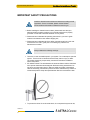
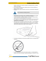
User Manual
for
Astra2Connect Terminal
version 3.1
User Manual for Astra2Connect Terminal
© 2009 Newtec cy.
The material contained in this document is confidential and intended for use only
by parties authorised by Newtec.
All Rights Reserved. No part of this document may be photocopied, reproduced,
stored in a retrieval system, or transmitted, in any form or by any means whether,
electronic, mechanical, or otherwise without the prior written permission of
Newtec cy.
Newtec cy
Laarstraat 5
9100 Sint-Niklaas, Belgium
General: +32 (0)3 780 65 00
www.newtec.eu
Fax +32 (0)3 780 65 49
General: [email protected]
version 3.1
i
User Manual for Astra2Connect Terminal
About this Manual
ABOUT THIS MANUAL
This User Manual is intended for the user of the Astra2Connect terminal. It
provides safety precautions, a description of the Astra2Connect terminal and a
detailed description of how to use the GUI (Graphical User Interface).
First-line troubleshooting information is also included.
Cautions and symbols
The following symbols appear in this manual:
A caution message indicates a hazardous situation that, if not
avoided, may result in minor or moderate injury. It may also refer
to a procedure or practice that, if not correctly followed, could
result in equipment damage or destruction.
A hint message indicates information for the proper operation of
your equipment, including helpful hints, shortcuts or important
reminders.
A reference message is used to direct to; an internal reference
within the document, a related document or a web-link.
Version history and applicability
version 3.1
ii
Document
version
Date
Subject
version
Author
Comments
1.9.2
November 21st 2007
R 1.6
GWI
Creation for this
software release
2.1
October 27th 2008
R 1.7
GWI
Creation for this
software release
3.1
January 28th 2009
R 1.8
GWI
Creation for this
software release
About this Manual
User Manual for Astra2Connect Terminal
Related documentation
The details of the installation and pointing of the Astra2Connect dish are described
in the Point&Play set-up manual.
version 3.1
iii
Important Safety Precautions
User Manual for Astra2Connect Terminal
IMPORTANT SAFETY PRECAUTIONS
Install the Astra2Connect modem and antenna according to local
regulations. For the US market, please visit the Federal
Communications Commission’s website at www.fcc.gov.
¾ Before installing the Astra2Connect modem, please make sure that your
electrical outlet is properly wired and your computer equipment is properly
grounded. Consult with a licensed electrician if in any doubt;
¾ Please read and understand all operating instructions in your user’s guide
located in the Astra2Connect modem shipping box;
¾ Please read and understand all of the safety precautions set forth in this user
manual and in the user’s guide prior to connecting any cables to the
Astra2Connect modem.
Always observe the following warnings:
• There are no user-serviceable parts in your system. Do not attempt to open the
system. There is a risk of electrical shock that may result in injury or death.
The system should only be opened by a technician trained and certified to
service the product;
• RF radiation hazard: The area between the antenna reflector and the iLNB feed
horn exposes hazardous electromagnetic field levels during transmission. Do
not place your head and/or body in that zone while the system is operational.
Take the necessary precautions to prevent access to the antenna by children or
unauthorised persons. Keep the space between feed horn and reflector clear!
• To prevent the risk of fire or electrical shock, do not expose the system to rain,
version 3.1
iv
Important Safety Precautions
User Manual for Astra2Connect Terminal
liquids or moisture. Do not place any objects containing liquids (e.g., glasses,
vases) on the system;
• Do not install the Astra2Connect modem if there is a risk of thunderstorm or
lightning activity in the area;
• The in-line power supply input power cord must not be used when damaged in
any way!
Always observe the following cautions:
• Always use the in-line power supply included with the Astra2Connect modem.
Using a different power supply may cause equipment damage;
• To ensure regulatory and safety compliance, use only the provided cables or
cables conform to the specifications within this manual;
• Do not open the unit. Do not perform any servicing other than that described in
the installation and troubleshooting instructions. Refer all other servicing to
qualified service professionals;
• Static electricity can damage the Astra2Connect modem. To avoid damaging
the Astra2Connect modem with static electricity, always touch the grounded
coaxial cable connector prior to disconnecting or re-connecting your Ethernet
cable from the Astra2Connect modem or your computer;
• To prevent overheating, do not block the ventilation holes on the sides and top
of the unit;
• To clean the outside of the unit, use a clean, dry cloth. To avoid equipment
damage, never clean the system using fluids, detergents or chemicals. Do not
version 3.1
v
User Manual for Astra2Connect Terminal
Important Safety Precautions
use pressurized air to remove dust from the unit;
• The user should install an AC surge suppressor in the AC outlet to which the
device is connected in order to avoid damage to the equipment from lightning
strikes and other electrical surges;
Notices:
• This product was qualified under test conditions that included the use of the
supplied cable between the components. To be in compliance with regulations,
the user must use this cable – or equivalent – and install it properly;
• Different types of cord sets may be used for connections to the main supply
circuit. Use only a main line cord that complies with all product safety
requirements of the country of use;
• Installation of this product must be in accordance with the applicable wiring
codes.
version 3.1
vi
User Manual for Astra2Connect Terminal
Table of Contents
TABLE OF CONTENTS
About this Manual .................................................................................................ii
Important Safety Precautions ...............................................................................ii
Table of Contents ..................................................................................................ii
1
Introduction..................................................................................................2
1.1
Astra2Connect Terminal Documentation .......................................................2
1.2
About the Astra2Connect Terminal ................................................................2
1.3
Installation Tasks ...........................................................................................2
2
Getting to know your Astra2Connect Terminal .........................................2
2.1
The IPmodem ...............................................................................................2
2.1.1
The IPmodem Front Panel.........................................................................2
2.1.2
The IPmodem Back Panel .........................................................................2
2.1.3
The Power Supply .....................................................................................2
2.1.4
Cables .......................................................................................................2
2.2
The iLNB........................................................................................................2
3
Terminal Web Interface................................................................................2
3.1
Prepare the Settings of Your Computer .........................................................2
3.2
How to Access the Terminal Web Interface? .................................................2
3.2.1
With Satellite Connection...........................................................................2
3.2.2
No Satellite Connection .............................................................................2
3.3
3.3.1
General Layout ..........................................................................................2
3.3.2
Menu Structure ..........................................................................................2
3.4
Reboot the IPmodem .....................................................................................2
3.5
LEDs in the Status Bar...................................................................................2
3.5.1
Ethernet LED .............................................................................................2
3.5.2
Satellite LED..............................................................................................2
3.5.3
Software LED ............................................................................................2
3.6
Introduction................................................................................................2
3.6.2
Overview ...................................................................................................2
3.6.3
Interface Statistics .....................................................................................2
3.7.1
vii
Status Page ...................................................................................................2
3.6.1
3.7
version 3.1
Overview Web Interface.................................................................................2
Configuration .................................................................................................2
Ethernet Interface ......................................................................................2
User Manual for Astra2Connect Terminal
Table of Contents
3.7.2
Satellite Interface.......................................................................................2
3.7.3
Multicast ....................................................................................................2
3.8
3.8.1
Software ....................................................................................................2
3.8.2
Hardware ...................................................................................................2
3.9
version 3.1
viii
Device............................................................................................................2
Antenna Pointing............................................................................................2
3.10
Test ...........................................................................................................2
3.10.1
On Screen Test Results ............................................................................2
3.10.2
Filed Test Results......................................................................................2
3.10.3
Test Descriptions.......................................................................................2
4
Appendix A – Local Network Configuration ..............................................2
5
Appendix B – Checking and Changing your IP Settings ..........................2
6
Appendix C – Troubleshooting Guide........................................................2
7
Appendix D – Acronyms..............................................................................2
8
Appendix E – Specifications .......................................................................2
9
Appendix F – Licenses ................................................................................2
User Manual for Astra2Connect Terminal
Introduction
1 INTRODUCTION
1.1
Astra2Connect Terminal Documentation
The Astra2Connect Terminal documentation exists out of three documents:
1. This document, describing the features and the terminal web interface of the
IPmodem;
2. The Point and Play manual describing the installation and pointing of your
antenna;
3. The pointing data, consisting of the information you need to point your antenna
to the correct position.
version 3.1
9
User Manual for Astra2Connect Terminal
Introduction
1.2
About the Astra2Connect Terminal
The Astra2Connect Terminal is state of the art equipment allowing cost effective,
plug & play connection to an extended variety of IP-based applications.
The Astra2Connect Terminal consists of:
• A small size, high quality, easy to install satellite antenna (79 cm);
• An interactive LNB (iLNB);
• An IPmodem providing an Ethernet connection to the computer of the end-user
or Local Area Network (LAN).
The interactive iLNB low power equipment is light weight, easy-to-install and highly
reliable. All parts are built using state-of-the-art microwave design that guarantees
an unequalled reliability for many years.
Connected to the interactive iLNB by means of transmit and receive cables, the
high speed IP modem provides an asymmetrical 2-way broadband access to IP
applications (e.g. Broadband Internet Access). Its small size, in line with the best
practice in the telecom and IT industries, makes it suited for any type of user,
business or consumer.
Figure 1 – Astra2Connect Terminal
version 3.1
10
User Manual for Astra2Connect Terminal
Introduction
1.3
Installation Tasks
To ensure proper installation of the Astra2Connect Terminal, the following tasks
must be performed.
These tasks are described in detail in the Point&Play Manual of your IPmodem.
Please read this Point&Play Manual carefully during installation.
¾ Prepare the installation site and unpack the devices;
¾ Select a suitable location to set up the antenna. A clear view to the South must
be available (satellite position). The distance between the antenna and the
IPmodem may not exceed 30 metres. Ideally, this distance shall not exceed 30
metres if making use of the cable provided with the Astra2Connect Terminal;
¾ Set up the antenna pole and attach the masthead to it;
¾ Attach the antenna to the masthead;
¾ Attach the iLNB to the antenna;
¾ Place the IPmodem in a clean, dry room at maximum 30 m (cable length) from
the antenna site;
¾ Connect the IPmodem to the iLNB using the Rx and Tx coax cables;
¾ Connect a computer (desktop or laptop) to the IPmodem;
¾ Power the IPmodem;
¾ Use a web browser on the computer to access the Terminal Web Interface;
¾ Point the antenna towards the correct satellite, fine-tune pointing and verify the
cross polarisation;
¾ Configure the terminal using the web interface and/or check the connectivity.
version 3.1
11
User Manual for Astra2Connect Terminal
Getting to know your Astra2Connect Terminal
2 GETTING TO KNOW YOUR ASTRA2CONNECT
TERMINAL
2.1
The IPmodem
2.1.1
The IPmodem Front Panel
(1)
(2)
(3) (4)(5)
Figure 2 – The IPmodem Front Panel
Nr
What
Description
(1)
Power LED
Green continuous – when powered up.
(2)
Warning LED
Yellow continuous – when the terminal is not
logged on to the satellite network.
(3)
LAN indicator LEDs
Left: Green continuous – link layer status.
Right: Green blinking – Ethernet frames are
received or transmitted.
(4)
Rx indicator LED
Green continuous – forward satellite signalling
receiving.
(5)
Tx indicator LED
Green blinking – traffic transmitting via the
satellite link.
Table 1 – Description of the Elements on the IPmodem Front Panel
2.1.2
The IPmodem Back Panel
(4)
(1)
version 3.1
12
(2)
(3)
(5)
Getting to know your Astra2Connect Terminal
User Manual for Astra2Connect Terminal
Figure 3 – The IPmodem Back Panel
Nr
What
Description
(1)
Tx connector
Indoor connection for the transmit coax cable.
(2)
Rx connector
Indoor connection for the receive coax cable.
(3)
Reset button
Reboot: press once briefly (hold less than 5
seconds);
Factory Reset: press and hold for more than 5
seconds.
Resetting will also reboot the terminal and
change all the IP-settings back to the default
factory settings.
(4)
15V power cable
connector
Power connector (5.5/2.5mm plug).
(5)
Ethernet cable connector
Connection for the LAN, type RJ-45 (Ethernet
cable).
Table 2 - Description of the Elements on the IPmodem Back Panel
2.1.3
The Power Supply
Figure 4 - IPmodem Power Supply
•
•
•
•
•
version 3.1
13
Universal input range: nominal 100 – 240 Volt / 50 – 60 Hz;
NEMA - IEC320/C8 socket;
CE approved;
Output 15V / 2A;
Plug 5,5 x 2,5 mm.
Getting to know your Astra2Connect Terminal
2.1.4
Cables
2.1.4.1
Ethernet Cables
User Manual for Astra2Connect Terminal
Included with your Astra2Connect Terminal is a crossed red Cat-5 Ethernet cable
with RJ-45 connectors. This cable is approximately 2 m long. It will be used to
connect the IPmodem to your computer.
The IPmodem Ethernet connection also supports auto cross-over.
Alternatively, so also a straight Ethernet cable can be used.
2.1.4.2
Coaxial Cables
There are two separate cables between the antenna and the indoor equipment: the
receive cable (Rx) and transmit cable (Tx). These coaxial cables (coax) are
approximately 1 cm in diameter and are 30 m long. Delivered with your system is a
combined twin cable with Rx and Tx cable attached to each other.
The F-connectors are not attached to the cable yet for easy installation of the
cable. Four screw-on connectors are delivered with the coax cable.
• RG6 foam equivalent;
• Specified up to 3GHz;
• F-connectors.
For an installation that requires a cable longer than 30 metres,
another cable (set) can be used. The overall requirement is then:
Attenuation @ 3000 MHz < 20 dB
The provided cable has an attenuation of ~ 14 dB @ 3000MHz (
30 m of cable).
Figure 5 - Coaxial Twin Cable with Connectors Attached
version 3.1
14
Getting to know your Astra2Connect Terminal
2.1.4.3
User Manual for Astra2Connect Terminal
The Pointing Tool
The pointing device, with the functionality as shown in Figure 6, is delivered with an
earphone as displayed in Figure 7 and appropriate battery.
Figure 6 – Pointing Device
The dimensions of the device are:
• Height: 29.02 mm;
• Length: 81.82 mm;
• Width: 61.56 mm.
Figure 7 – Earphone
version 3.1
15
Getting to know your Astra2Connect Terminal
2.1.4.4
User Manual for Astra2Connect Terminal
Antenna
Overview
The antenna comprises five parts:
• Antenna pole;
- See below for the antenna pole requirements;
• Masthead;
- Completely pre-assembled;
- Elevation and azimuth fine-pointing adjust cams.
• Antenna reflector (dish);
- 79 x 85 cm pressed sheet metal with heavy-duty rim;
- Steel is passivated and epoxy powder coated;
- Fixed with 4 bolts.
• Feed arm;
- Feed Arm is a steel part, precision formed;
- Steel is passivated and epoxy powder coated;
- Fixed to masthead with 2 x M6 bolts;
- Feed clamp snaps inside feed arm;
- Feed clamp is Glass-Filled Nylon;
- All plastic parts are UV-stabilised.
• iLNB (see section 8.2 for more information).
Figure 8 - Antenna Overview & Elements
Antenna Pole Requirements
When selecting an antenna pole, keep in mind the following dimensions:
• Dimensions;
- Minimum diameter: 40mm;
• Maximum diameter: 70mm;
• Galvanised steel;
version 3.1
16
User Manual for Astra2Connect Terminal
Getting to know your Astra2Connect Terminal
• Solid base / fixation.
The mechanical forces that need to be considered in the fixation of the antenna
pole are shown in the picture below.
Figure 9 - Antenna Pole Stress and Forces
2.2
The iLNB
The iLNB has an integrated casing and is fully sealed except for its ventilation
slots.
(2)
(1)
(3)
Figure 10 - iLNB > Perspective and Bottom View
Nr
What
Description
(1)
Feed horn
Radiating feed horn of the iLNB, pointed
towards reflector.
(2)
Tx connector
Outdoor connection for the transmit coax cable.
(3)
Rx connector
Outdoor connection for the receive coax cable.
Table 3 - Description Elements of the iLNB
version 3.1
17
User Manual for Astra2Connect Terminal
Terminal Web Interface
3 TERMINAL WEB INTERFACE
3.1
Prepare the Settings of Your Computer
Check if your computer is set to DHCP. This way the computer can receive an IP
address from the IPmodem.
Follow the procedure in Appendix B – Checking and Changing your IP Settings to
check and/or change your IP settings.
3.2
How to Access the Terminal Web Interface?
3.2.1
With Satellite Connection
In the normal operational mode a connected computer should be configured in
DHCP mode to retrieve an IP address automatically and to retrieve the DNS
server. The terminal acts as a DHCP server for the computer.
Browse to the web interface
¾ Type the IPmodem’s address in the address bar of the browser: 192.168.1.1.
You will be re-directed to the Status page of the terminal.
Figure 11 – The IPmodem’s Address in the Address bar of the browser
Alternatively, use the Default Gateway address to reach the web
interface. See Appendix A – Local Network Configuration for more
information.
It is possible that during first logon the terminal will perform an
upgrade with the latest software since you cannot login using the
old SW. This process can take up to ten minutes. You may NOT
interrupt the terminal yourself during this period, e.g. by
rebooting or powering down.
If newer software is available, the terminal will:
• Download this software;
• Install this software
• Reboot the terminal;
• Logon to the network again.
version 3.1
18
User Manual for Astra2Connect Terminal
Terminal Web Interface
3.2.2
No Satellite Connection
Make sure your computer is able to receive an IP address via DHCP, by following
the procedure in Appendix B – Checking and Changing your IP Settings.
When the terminal is not linked to the satellite network, after three minutes, the
computer will automatically receive its IP address, via DHCP, from the IPmodem
and you will then be able to browse the web interface:
If no DHCP address is assigned to your terminal: remove the Ethernet cable from
your computer, wait a few seconds, and plug the Ethernet cable back into your
computer.
¾ Type the IPmodem’s address in the address bar of the browser: 192.168.1.1.
You will be redirected to the Status page of the terminal.
If the problem remains, you need to assign a static IP address to your computer by
following the procedure in Appendix B – Checking and Changing your IP Settings.
3.3
Overview Web Interface
3.3.1
General Layout
A
B
C
Figure 12 – Page Layout of Web Interface
Each of the web interface pages contains the same elements.
• A – Banner
The banner contains the Newtec logo and shows the Air MAC address.
• B – Status bar
version 3.1
19
D
Terminal Web Interface
User Manual for Astra2Connect Terminal
The status bar always shows the most important status LEDs. This information will
be specified in the body of the Status page.
• C – Menu structure
On the left hand side of the page the site navigation is found. Click an item to
select it. The menu structure may differ depending on your login status.
• D – Body
The actual content of the web interface is shown in the body. It always shows the
page title and one or more content blocks or forms.
3.3.2
Menu Structure
The menu structure of the web interface of the web interface is described below
(see Figure 13).
• Status
Check on the device and network status.
• Configuration
- Ethernet Interface
Check and alter the Ethernet interface configuration.
- Satellite Interface
Check and alter the Satellite interface configuration.
- Multicast
Check and alter the Multicast configuration.
• Device Interface
- Software
Check on or alter the software version.
- Hardware
Check the Hardware version.
• Antenna Pointing
- Repoint your antenna
• Test
Run tests on the device.
Figure 13 - Menu Structure for the User
version 3.1
20
User Manual for Astra2Connect Terminal
Terminal Web Interface
3.4
Reboot the IPmodem
See section 2.1.1 for similarities with the hardware button reboot.
Figure 14 – Location of the Reboot Link
¾ Click the [Reboot] link at the right of the status bar to reboot the terminal.
The terminal will reboot and return to the Status page. This may take up to one
minute, including satellite link initialisation.
The reboot of the terminal is needed when a (re)configuration has
been performed. Changes may not take effect until after the next
reboot
3.5
LEDs in the Status Bar
3.5.1
Ethernet LED
The Ethernet LED gives the general status of the Ethernet connection to the
IPmodem.
LED colour code
Description
Red
Connection is not OK.
Yellow
Connection is OK, but no DHCP address is given.
Green
A DHCP address is given and the connection is OK.
Table 4 - Status LEDs > Ethernet
3.5.2
Satellite LED
The Satellite LED gives the general status of the Satellite connection to the
IPmodem.
version 3.1
21
LED colour code
Description
Red
No connectivity, no valid signal received.
User Manual for Astra2Connect Terminal
Terminal Web Interface
LED colour code
Description
Yellow
A valid signal was received. The terminal is busy logging in
on the satellite network.
Green
The system is operational and the user is logged in on the
satellite network.
Table 5 - Status LEDs > Satellite
3.5.3
Software LED
The Software LED gives the general status of the installed software or the
updates.
LED colour code
Description
Red
The terminal has a newer software version than the running
software version, and
The newer software version was not selected because the
software validation process failed.
See Appendix C – Troubleshooting Guide for possible
actions and follow-up.
Yellow
The terminal is retrieving new software via satellite. This can
take up to 10 minutes.
Green
No problem. The terminal is running with the latest software
version.
Table 6 - Status LEDs > Software
3.6
Status Page
3.6.1
Introduction
In normal operation, when the terminal is pointed and active, there two parts to the
Status Page as shown in Figure 15, which are described in more detail in the
following sections:
• Overview:
This part gives an overview of the IPmodem, demodulator and software state.
• Interface Statistics:
This part gives an overview of the IP modem statistics.
version 3.1
22
User Manual for Astra2Connect Terminal
Terminal Web Interface
Figure 15 – Status Page when the Terminal is Pointed
When the terminal is not yet pointed a third part is shown:
• Pointing:
This part gives an overview of the pointing status and pointing carrier selection.
3.6.2
Overview
3.6.2.1
Modem State
The IPmodem state is indicated by a coloured LED and a state description. For the
LED colour code, refer to Table 7. The possible modem state descriptions are
given below.
Modem state
Description
Awaiting installer action
The terminal is waiting for an action of the installer.
Satellite network lookup
The terminal is looking for the satellite network.
Synchronising
The terminal found the satellite network and time
synchronisation.
Synchronised
The terminal is synchronised and can directly log in
on the satellite network when IP traffic is received via
the Ethernet interface.
Network login
The terminal is trying to log in on the satellite
network.
Operational
The terminal is logged in.
Table 7 - Status Page > Modem State
version 3.1
23
User Manual for Astra2Connect Terminal
Terminal Web Interface
3.6.2.2
Demodulator
The Demodulator state is indicated by a coloured LED and a state description.
LED colour code
Description
Green
The demodulator is locked.
Red
The demodulator is not locked.
Table 8 - Status Page > Demodulator LED
The demodulator state is built as follows (see Table 9 for more details):
• -95.0 dBM, Es/No: 23.2 dB, <Satellite network name>
Demodulator label value
Description
y dBm
Indication of the received signal strength expressed
in dBm. This indication can change when going from
pointing mode to operational mode.
Es/No
Es/No is an indication of the received signal quality
expressed in dB. This indication can change when
going from pointing mode to operational mode.
Table 9 - Status Page > Demodulator Labels
3.6.2.3
Info by Error State
An error message can be displayed. This error message displays the current error
status and will be reset when the terminal has entered the satellite network and the
terminal is operational.
Please refer to Appendix C – Troubleshooting Guide for more
details on possible errors and actions needed to resolve the
occurring error
3.6.2.4
Software Version
The running software version is indicated by its version number. See also
Appendix C – Troubleshooting Guide.
3.6.2.5
Pointing
This section of the web interface displays information on the pointing status of the
terminal.
The following status can be viewed:
• Status when the antenna is not pointed as shown in Figure 16, giving the option
to start pointing or to skip pointing. Where two pointing carriers are available,
version 3.1
24
User Manual for Astra2Connect Terminal
Terminal Web Interface
one can choose the used carrier as shown in Figure 17.
• Status during the pointing of the antenna; see Figure 18. Click on Pointing
Completed when the antenna is pointed;
• Status when pointed successfully or pointing skipped as shown in Figure 19.
This is the status during normal operation of the terminal after pointing;
For more details about the functioning of these buttons and
navigation between screens refer to the Point&Play manual.
Figure 16 - Web Interface > Status when not Pointed – One pointing Carrier
Figure 17 - Web Interface > Status when not Pointed – Two pointing Carriers
Figure 18 - Web Interface > Pointing
Figure 19 - Web Interface > Antenna Pointing > Status when Pointed or Pointing is
Skipped
version 3.1
25
User Manual for Astra2Connect Terminal
Terminal Web Interface
During normal operation the
button is shown
via the Antenna Pointing button in the menu bar and should only
be used in case pointing documentation is available and the
antenna must be re-pointed
3.6.3
Interface Statistics
Modem state
Description
Interfaces
Directions
Statistics
Ethernet
interface
User side interface (Ethernet frames)
Satellite
interface
Satellite side interface (IP packets)
Rx
Receive
Tx
Transmit
Bytes
Total number of received (or transmitted)
bytes
Packets
Received (or transmitted) Ethernet frames
or IP packets
Errors
Number of occurred errors
Dropped
Dropped Ethernet frames or IP packets
Table 10 - Status Page > Interface Statistics
3.7
Configuration
The reboot of the terminal is needed when a (re)configuration has
been performed. Changes may not take effect until after the next
reboot.
3.7.1
Ethernet Interface
This section describes the interface between the computer and the IPmodem.
version 3.1
26
User Manual for Astra2Connect Terminal
Terminal Web Interface
3.7.1.1
View the Ethernet Interface Configuration
Figure 20 - Web Interface > View Configuration Ethernet Interface
3.7.1.2
The Parameters of the Ethernet Interface
The displayed parameters and their description are shown below.
Parameter
Description
Eth MAC address
MAC address of the Ethernet interface
Management IP
address
Management IP address of the Ethernet interface
Netmask
Network range for the user’s LAN
Table 11 - Configuration Page > Ethernet Interface Parameters
version 3.1
27
User Manual for Astra2Connect Terminal
Terminal Web Interface
3.7.1.3
Modify the Ethernet Interface Configuration
Figure 21 - Web Interface > Edit Configuration Ethernet Interface
¾ Click on
in the Web Interface > View Configuration Ethernet interface
(Figure 21) to change the Ethernet Settings.
¾ Edit the parameters to be changed.
¾ Click on
in the Web Interface > Edit Configuration Ethernet interface
(Figure 21) to save the new settings.
The Ethernet interface configuration is now saved!
3.7.2
Satellite Interface
These settings may only be changed upon advice of your internet
service provider!
3.7.2.1
Introduction
This section describes the interface settings between the terminal and the satellite.
Every satellite interface setting consists of:
Initial Receive Carrier
This is the initial receive carrier via which the IPmodem will try to gain access to the
network.
version 3.1
28
Terminal Web Interface
User Manual for Astra2Connect Terminal
Pointing Carrier
This carrier is needed to enable antenna pointing via the Point&Play mechanism.
When two different pointing carriers are assigned to the terminal, the installer can
perform his pointing on two different pointing carriers. At least one pointing carrier
must be enabled.
3.7.2.2
View the Satellite Interface Configuration
Maximum two initial receive carrier settings and pointing carrier settings can be
assigned and displayed. Only the settings that are enabled are displayed. How to
change the satellite interface configuration is described in section 3.7.2.3.
If two settings for a carrier are enabled and displayed, the preferred initial receive
carrier is marked by
.
If two settings for a carrier are enabled and displayed, the default pointing carrier is
The final selection of the pointing carrier that is used for pointing is
marked by
done in the Status Page as shown in Figure 17, where the non-default pointing
carrier can be selected.
In the example of Figure 22, two initial receive carriers and two pointing carriers
are enabled. Initial Receive Carrier 1 is marked as preferred, and Pointing Carrier 2
is set as default.
Figure 22 - Web Interface > View Configuration Satellite Interface
3.7.2.3
The Parameters of the Satellite Interface
The displayed parameters and their descriptions are shown in the table below.
version 3.1
29
User Manual for Astra2Connect Terminal
Terminal Web Interface
Parameter
Description
Initial Receive Carrier
Preferred
Mark for the preferred Initial Receive Carrier
Transport Mode
DVB-S;
DVB-S2 (Constant Coding Modulation - CCM).
Frequency
Initial receive frequency (GHz)
Symbol Rate
Initial receive symbol rate (Mbaud)
DVB-S2 Roll-off Factor
Only configurable in DVB-S2 mode. Excess bandwidth of
the Rx signal spectrum.
35 %;
25 %;
20 %.
Pointing Carrier
Default
Mark for the default pointing carrier
Transport Mode
DVB-S;
DVB-S2 (Constant Coding Modulation - CCM).
Frequency
Initial receive frequency (GHz)
Symbol Rate
Initial receive symbol rate (Mbaud)
DVB-S2 Roll-off Factor
Only configurable in DVB-S2 mode. Shape of the Rx
signal spectrum.
35 %;
25 %;
20 %.
Orbital Position
Orbital position of the satellite in degrees and East/West
selection.
Table 12 - Configuration Page > Satellite Interface Parameters > Initial Receive
Carrier
3.7.2.4
Edit the Satellite Interface Configuration
in the Web Interface > View Satellite Configuration Interface as
¾ Click on
shown in Figure 22.
¾ Edit the parameters to be changed and as described in Figure 23.
An initial receive carrier setting or pointing carrier setting can only
be enabled if the frequency of the configuration is filled in
version 3.1
30
Terminal Web Interface
User Manual for Astra2Connect Terminal
Figure 23 - Web Interface > Edit Configuration Satellite Interface
¾ Click on
in the Web Interface > Edit Configuration Ethernet interface
(Figure 23) to save the new settings;
The satellite interface configuration is now saved and the changes in the
configuration are displayed.
Figure 24 – Example of Satellite Interface Configuration Changes
¾ Click on reboot at the bottom of the page;
¾ Click on Normal Reboot to confirm and execute the reboot;
version 3.1
31
Terminal Web Interface
User Manual for Astra2Connect Terminal
Figure 25 – Reboot in Progress
¾ Click on Click here to return to the web interface and wait a few minutes.
The satellite interface configuration is now effective.
3.7.3
Multicast
The satellite can send several sessions to a number of Astra2Connect terminals at
the same time.
This is IPmulticasting. There are two configurations possible in the Astra2Connect
terminal to receive these programs:
• Static IP addresses: these are IP addresses where the sessions are received.
You will be provided with these addresses if needed;
• IGMP: this is a protocol that lets you receive multicast sessions (maximum 10)
without entering specific IP addresses.
3.7.3.1
View the Multicast Configuration
Figure 26 - Web Interface > View Configuration Multicast
3.7.3.2
The Multicast Parameters
The displayed parameters and their description are shown below.
version 3.1
32
User Manual for Astra2Connect Terminal
Terminal Web Interface
Parameter
Description
Multicast Mode
Disabled: Multicast mode is disabled.
Static: The active Multicast Configuration is based on
entered Static Multicast IP Addresses.
IGMP Dynamic: Dynamic IGMP multicast mode.
Static Multicast IP
Address 1-10
Maximum 10 multicast IP Addresses can be assigned
and active in case of Static Multicast Mode.
Table 13- Configuration Page > Multicast parameters
3.7.3.3
Edit the Multicast Configuration
Figure 27 – Web Interface > Edit Multicast Configuration
¾ Click on
in the Web Interface > View Multicast configuration (Figure 26)
to Change the Ethernet Settings;
¾ Edit the parameters to be changed;
¾ Click on
in the Web Interface > Edit Multicast configuration (Figure 27) to
save the new settings.
The Multicast configuration is now saved!
The response screen for a Disabled Multicast configuration:
version 3.1
33
Terminal Web Interface
User Manual for Astra2Connect Terminal
Figure 28 – Web Interface > Confirmation of Disabled Multicast Configuration
In case an invalid multicast IP address is replacing a valid multicast IP address, the
last valid multicast IP address will still be in use.
The response screen for a Committed Multicast configuration:
Figure 29 – Web Interface > Confirmation Committed Multicast Configuration
version 3.1
34
User Manual for Astra2Connect Terminal
Terminal Web Interface
3.8
Device
3.8.1
Software
3.8.1.1
Introduction – General Case
The terminal software is automatically upgraded over the satellite without any user
interaction. In general, the only requirement for an upgrade to be successful is for
the terminal to have satellite connectivity during the time of upgrade.
To allow a secure terminal software upgrade mechanism, the flash of the modem
can contain two different software versions. A newly installed software version has
to pass an automatic software validation procedure. After a software upgrade, the
IPmodem is automatically reset.
Figure 30 - Web Interface > View Software Configuration
Table 14 gives a description of the parameters in the Software menu:
Parameter
Description
Software Download Identifiers
To uniquely identify the terminal variant for software download triggered from the
hub side, the following keys are reserved for SW update.
Software Download
Manufacturer ID
Software download manufacturer Identifier (639 for
Newtec devices)
Software Download
Hardware ID
Software downloads hardware Identifier.
Software version
Currently Running
Software Version
version 3.1
35
The currently installed software version is displayed.
When an alternate software version is available, you will
User Manual for Astra2Connect Terminal
Terminal Web Interface
Parameter
Description
be provided with a link Try Alternate Version.
Alternate Software
Version
Only displayed when an alternative software version is
present.
Table 14 - Software Page
3.8.1.2
Software Upgrade
A newly installed software version must pass an automatic software validation
procedure. When this software validation process fails, the old software version
remains in use. The passive bank now contains a newer software version that did
not pass the validation process. In this case, the user has the possibility to retrigger the validation process. This situation can occur when a user turns off his
IPmodem during the validation process or when satellite connectivity was not
possible to establish during the validation process.
It is possible that the terminal performs a software update during
the first logon. This process can take up to ten minutes. You may
NOT interrupt the terminal yourself during this period by e.g.
rebooting or powering down
1.7.1.3
1.7.1.4
Figure 31 - Web Interface > Software (Alternate Version)
To re-trigger the validation process:
¾ Click the link Try Alternate Version;
The Software Upgrade page will be displayed indicating the new software version
number (see below).
¾ If the web interface doesn’t refresh automatically, navigate back to the Status
page.
A total reboot, including satellite link initialisation might take up to 1 minute.
version 3.1
36
User Manual for Astra2Connect Terminal
Terminal Web Interface
Figure 32 - Web Interface > Software Upgrade Confirmation
When a newer version is present and validation fails, the software
LED is red.
Also read section 3.5 for more information on the meaning of the
software status LEDs
3.8.2
Hardware
Figure 33 - Web Interface > Hardware
version 3.1
37
User Manual for Astra2Connect Terminal
Terminal Web Interface
Below are given the displayed parameters and their description.
These values are read only.
Parameter
Description
Device
Hardware ID
Hardware identifier of the modem
Hardware Version
Hardware version number of the modem
Table 15 - Configuration Page > View Hardware Parameters
3.9
Antenna Pointing
Figure 34 – Antenna Pointing
In case the antenna should be re-pointed click the
button.
The pointing procedure is described in the Point&Play Manual.
The GUI interface is described in paragraph 3.6.2.5.
3.10 Test
To view the functioning status of the Astra2Connect Terminal, or to identify
problems that may occur, tests can be run on the terminal:
version 3.1
38
User Manual for Astra2Connect Terminal
Terminal Web Interface
Figure 35 – Web Interface > Test Overview
Mark (
) or unmark (
) a test depending on the tests to be run.
Section 3.10.3 gives a description of the tests which can be performed.
Click on the
-button to begin the test.
3.10.1 On Screen Test Results
As a result, a screen with the requested test results will be shown, see Table 16 –
Possible States of IPmodem Tests.
Running test
Test waiting to run
Successfully ran test
Unsuccessfully ran test
Table 16 – Possible States of IPmodem Tests
version 3.1
39
Terminal Web Interface
User Manual for Astra2Connect Terminal
Figure 36 – On-Screen Test Results
3.10.2 Filed Test Results
Click on the
-button to begin the test. As a result, a web page
with the test results in text format will be provided. The test results can now be
saved in a text file from the browser, as shown in Figure 37.
version 3.1
40
Terminal Web Interface
User Manual for Astra2Connect Terminal
Figure 37 – Web Interface > Test > Export to Text File
3.10.3 Test Descriptions
This section provides an overview of the tests that can be run on the IPmodem.
3.10.3.1 Software Test
The Software test verifies the validity of the software.
3.10.3.2 Ethernet/LAN Test
The Ethernet/LAN exists of three tasks:
¾ Checking the Ethernet physical layer;
¾ Obtaining the IP address off the computer connected to the IPmodem;
¾ Checking the IP address of the computer, provided via DHCP by the IPmodem.
version 3.1
41
Terminal Web Interface
User Manual for Astra2Connect Terminal
3.10.3.3 Satellite Connection Test
The Satellite connection test is composed of three tests:
• The Physical layer test, checks if the physical layer of the IPmodem – satellite
connection is able to receive data;
• The Data link layer test, checks if the Astra2Connect system is able to send
data to the satellite;
• The Network layer test, checks the IP connection.
3.10.3.4 Traffic Test
The Traffic test is composed of three tests:
• A ping traffic test, tests if ping packets can be transported over the network from
the IPmodem, over the satellite to the hub site.
The following fields can be filled in:
- Ping packet size (bytes): minimum 1 and maximum 65,507 bytes;
- Number of pings: minimum 1 and maximum 100.
• The DNS traffic test resolves a URL via a name server at the hub site.
The Http GET traffic test, verifies the TCP acceleration and pre-fetching.
version 3.1
42
Appendix A – Local Network Configuration
User Manual for Astra2Connect Terminal
4 APPENDIX A – LOCAL NETWORK CONFIGURATION
The following provides an overview of IP network configurations. The situation is
explained for connecting a single computer to the IPmodem or for connecting a
router with its own LAN to the IPmodem.
To correctly interpret the figures, keep in mind the following convention:
Figure 38 - Network Configuration Legend
4.1
Connect a Single Computer to the IPmodem
Once the computer is connected to the IPmodem’s Ethernet interface, set the
computer’s IP settings to DHCP enable.
Please refer to section 5 for a detailed explanation on how to
change the IP settings
Figure 39 - CPE Network Configuration > Single Computer
The IPmodem web interface can be reached on:
• 192.168.1.1 (default web interface address);
• The Default Gateway address.
We recommend using a Software fire-wall on the computer which
is connected to the IPmodem.
To know the Default Gateway address, type the ipconfig
command in the command line interface
version 3.1
43
Appendix A – Local Network Configuration
4.2
User Manual for Astra2Connect Terminal
Connect a LAN to the IPmodem
To connect the IPmodem to a network, a router is needed. The IPmodem has to be
connected to the Internet/WAN interface of the router. In the router configuration,
the Internet/WAN interface must be set to DHCP mode. Please refer to the router’s
manual for a description of how to set the Internet interface to DHCP mode and
how to connect the router to your LAN (local area network).
Please refer to section 5 for a detailed explanation on how to
change the IP settings
Figure 40 - Network Configuration > LAN
The IPmodem web interface is accessible through the IPmodem
default gateway. The IPmodem default gateway address can be
looked up through the router’s web interface.
Please refer to your router’s manual for a description of how to
look up the default gateway address.
version 3.1
44
Appendix B – Checking and Changing your IP
User Manual for Astra2Connect Terminal
Settings
5 APPENDIX B – CHECKING AND CHANGING YOUR IP
SETTINGS
5.1
Introduction
The following sections describe how to check if your computer is able to receive an
IP address via DHCP. The sections also describe how to change your IP settings
to enable your computer to accept an IP address assigned by the IP modem.
5.2
Windows Vista
¾ Open the Start Menu and select Control Panel;
¾ Select the option View network status and tasks;
version 3.1
45
Appendix B – Checking and Changing your IP
User Manual for Astra2Connect Terminal
Settings
¾ Select Manage network Connections;
¾ Double click on Local Area Connection;
¾ Select the button Properties at the bottom;
¾ Select Internet Protocol Version 4 (TCP/IPv4);
version 3.1
46
Appendix B – Checking and Changing your IP
User Manual for Astra2Connect Terminal
Settings
¾ Select Properties;
¾ Make sure “Obtain an IP address automatically’ and Obtain DNS server
address automatically are selected;
version 3.1
47
Appendix B – Checking and Changing your IP
User Manual for Astra2Connect Terminal
Settings
¾ Click the OK button.
5.3
Windows XP
¾ Open the Start Menu and select Control Panel;
¾ Open the Network Connections window;
version 3.1
48
Appendix B – Checking and Changing your IP
User Manual for Astra2Connect Terminal
Settings
¾ Right click on the active LAN connection and select Properties;
The Local Area Connections Properties dialogue will open.
¾
Select the tab General;
¾
Scroll down the items and select Internet Protocol (TCP/IP);
¾
Click the Properties button;
The Internet Protocol (TCP/IP) Properties dialogue will open.
By default, the dialogue is set as shown below
version 3.1
49
Appendix B – Checking and Changing your IP
User Manual for Astra2Connect Terminal
Settings
.
¾ Select the tab General;
If the radio button Obtain an IP address automatically is selected, your computer
is able to receive an IP address.
If the radio button Obtain an IP address automatically is not selected:
¾ Select the radio button Obtain an IP address automatically;
¾ Click the OK button.
Your computer will now be able to accept an IP address from the IP modem.
5.4
Mac OS X
¾ Click on your Apple menu and choose System Preferences:
version 3.1
50
Appendix B – Checking and Changing your IP
User Manual for Astra2Connect Terminal
Settings
¾ Double-click on the Network icon;
¾ Click on the adapter that you wish to change (usually Built-in Ethernet) and then
click the Configure... button
version 3.1
51
Appendix B – Checking and Changing your IP
User Manual for Astra2Connect Terminal
Settings
;
¾ Go to the TCP/IP tab. If your computer is configured to use a dynamic IP
address, you should see a screen such as the one below (notice Using DHCP
in the drop-down box next to Configure);
¾ This is where you can change your DNS settings, by entering the appropriate
DNS servers in the Domain Name Servers (Optional) box;
¾ If not already selected, select Using DHCP from the drop down box called
Configure in the TCP/IP tab. You should get a screen shot as above;
¾ Apply your settings by clicking the Save button.
version 3.1
52
Appendix B – Checking and Changing your IP
Settings
version 3.1
53
User Manual for Astra2Connect Terminal
Appendix C – Troubleshooting Guide
User Manual for Astra2Connect Terminal
6 APPENDIX C – TROUBLESHOOTING GUIDE
We would appreciate any useful feedback that can help us to
complete this section. The position of the LEDs described in the
Problem indication column is described in section 3.4.
Problem indication
version 3.1
54
Possible solution
No connectivity with IPmodem web
interface.
LED error indication:
The Rx indicator LED is off
The Warning LED is orange
The IPmodem has no connectivity with the
satellite network (section 3.2.2).
Check if the computer can receive an IP
address via DHCP, as described in
Sectrion 5.
If the computer can receive an IP address:
unplug the Ethernet cable from your
computer, wait for more than 3 minutes and
plug the Ethernet cable in, again.
Web interface error info:
Modem State :
Awaiting installer action
Modem LED is red
Your modem has not been pointed. Consult
the Point&Play manual to execute the
pointing process.
Web interface error info:
Modem State : antenna pointing
Your modem is currently in the pointing
state. Consult the Point&Play manual to
execute the pointing process.
Web interface error info:
No demodulator lock
Modem LED is red
LED error indication:
The RX indicator LED is off
Error in handling of the Rx signal. The Rx
demodulator cannot lock.
Verify the pointing of the antenna.
Verify the connectivity between the
IPmodem and the antenna.
Verify the configuration of the satellite
interface: frequency, polarisation, symbol
rate…
Web interface error info:
Terminal specific forward carrier
lookup is ongoing
LED error indication:
Warning LED is on, RX LED is on
The modem is determining on which traffic
carrier it is provisioned. If
the message does not disappear within 10
minutes, reset the modem
(section 3.4). If the error is still occurring
after a number of hours, contact your ISP :
- to report the problem;
- to check if your IPmodem is provisioned in
the network
Appendix C – Troubleshooting Guide
Problem indication
The time synchronisation process failed.
Reset the IPmodem (section 3.4).
Contact your ISP if this error is persistent
for more than four hours.
The error can be an indication of a general
network problem
Error information in the web
interface:
Synchronisation lost
LED error indication:
Warning LED is on, RX LED is on
The time synchronisation is lost.
Reset the IPmodem (section 3.4).
Contact your ISP if this error is persistent
for more than four hours.
The error can be an indication of a general
network problem.
Error information in the web
interface:
Network login failed
Error information on the IPmodem:
LED error indication:
Warning LED is on, RX LED is on.
The IP modem could not login to the
satellite
Verify if the TX cable is correctly
connected.
If the TX cable is correctly connected and
the error is still occurring after a number of
hours, contact your ISP :
- to report the problem;
- to check if your IPmodem is provisioned in
the network
Error information in the web
interface:
Network Layer configuration failed
LED error indication:
Warning LED is on, RX LED is on
An error occurred during the configuration
of the network layers after a valid satellite
network login.
Reset the IPmodem (section 3.4).
Contact your ISP if this error is persistent
for more than four hours.
Error information in the web
interface:
TCP acceleration service failed
LED error indication:
Warning LED is on, RX LED is on
An error is detected in the TCP acceleration
service. Reset the IPmodem.
Reset the IPmodem (section 3.4)
Contact your ISP if this error is persistent
for more than four hours.
Error information in the web
interface:
Network connectivity lost
LED error indication:
Warning LED is on, RX LED is on
The connectivity with the satellite network is
lost. Reset the IPmodem.
Reset the IPmodem (section 3.4)
Contact your ISP if this error is persistent
for more than four hours.
Error information in the web
interface:
The activation of the installation carrier test
mode failed because the terminal was not
in the correct state.
• Installation carrier setup failed
• Warning LED is on, RX LED is on
Table 17 – Troubleshooting Table
55
Possible solution
Error information in the web
interface:
Synchronisation process failed
LED error indication:
Warning LED is on, RX LED is on
LED error indication:
version 3.1
User Manual for Astra2Connect Terminal
User Manual for Astra2Connect Terminal
Appendix D – Acronyms
7 APPENDIX D – ACRONYMS
version 3.1
56
Acronym / term
Description
8PSK
8 Phase Shift Keying
AC
Alternating Current
ACS
Access Control Server
ARP
Address Resolution Protocol
ATM
Asynchronous Transfer Mode
BER
Bit Error Rate
C/N
Carrier to Noise ration
CCM
Constant Coding Modulation
CE approved
Conformité Européenne (European health & safety
product label)
DC
Direct Current
DHCP
Dynamic Host Configuration Protocol
DVB
Digital Video Broadcasting
DVB-RCS
Digital Video Broadcasting – Return Channel
Satellite
DVB-S, DVB-S2
Digital Video Broadcasting over Satellite (2)
EIRP
Effective Isotropic Radiated Power
EN
ETSI Norm
FCT
Frame Composition Table
FEC
Forward Error Correction
FTP
File Transfer Protocol
GMSK
Gaussian Minimum Shift Keying
G/T
Antenna Gain-to-System Noise Temperature Ratio
GUI
Graphical User Interface
HTTP
Hyper Text Transfer Protocol
ICMP
Internet Control Message Protocol
IEEE
Institute of Electrical and Electronics Engineers,
iLNB
Interactive Low Noise Block-down converter
IP
Internet Protocol
ISP
Internet Service Provider
IT
Information Technology
User Manual for Astra2Connect Terminal
Appendix D – Acronyms
Acronym / term
Description
LAN
Local Area Network
LED
Light Emitting Diode
LNB (iLNB)
Low Noise Block-down converter
MAC address
Medium Access Control
MF-TDMA
Multi Frequency Time Division Multiple Access
MPEG
Moving Picture Experts Group
NCR
Network Clock Reference
NIT
Network Information Table
Nm
Newton metre
ODU
Outdoor Unit
PAT
Program Association Table
PMT
Program Map Table
QPSK
Quadrature Phase Shift Keying
RCS
Return Channel Satellite
RF
Radio Frequency
RFC
Request for Comments
RMT
RCS Map Table
RT
Reporting Tool
Rx
Receive
SAP
Satellite Access Provider
SCT
Superframe Composition Table
SDT
Service Descriptor Table
SEMS
Satellite Earth Station Management System
TBTP
Time Burst Time Plan
TCP (TCP/IP)
Transmission Control Protocol
TCT
Time Composition Table
TMS
Terminal Management System
TS
Transport Stream
Tx
Transfer
UDP
User Datagram Protocol
VAC
Volts, Alternating Current
VSAT
Very Small Aperture Terminal
WCT
Waveform Composition Table
Table 18 - Acronyms
version 3.1
57
Appendix E – Specifications
User Manual for Astra2Connect Terminal
8 APPENDIX E – SPECIFICATIONS
8.1
IPmodem (indoor unit)
Forward Channel
• Modulation/coding
- DVB-S
- Rate 1/2, 2/3, 3/4, 5/6, 7/8 (QPSK)
- DVB-S2 CCM
- Rate 1/2, 2/3, 3/4, 5/6, 7/8 (8PSK)
- Rate 1/2, 2/3, 3/4, 5/6, 7/8 (QPSK)
• Symbol rate
- DVB-S : 1-45 Mbaud
- DVB-S2 : 3-30 Mbaud
• MPEG TS rates
- 1-80 Mbps
Return Channel
• Modulation/coding
- GMSK BT = 0.5
- Rate 1/2, 2/3, 3/4 Turbo (GMSK)
• Symbol rate
- 128, 256 Kbaud
• ATM data rates
- 143 kbps
IDU and IFL Interface
• RF In
- Connector: F (female)
- Impedance: 75 Ohm
- Acquisition range : +/- 5 MHz
- Frequency: 950 – 2100 MHz
- Rx level: -65 to -25 dBm
• RF Out
- Connector: F (female)
- Impedance: 75 Ohm
- Frequency: 2750-2900MHz (Ku band)
- Tx level: 0 dBm
Performance
• IP data Throughput
- Up-to2 Mbit/s IP forward
- Up-to 143 kbit/s ATM return
version 3.1
58
Appendix E – Specifications
User Manual for Astra2Connect Terminal
Management
- Web GUI
LAN interfaces
- Ethernet 10/100 baseT (RJ-45 connector)
Standards
-
EN 302307: DVB-S2
EN 300421: DVB-S
EN 301790: DVB-RCS
EN 50478: SATMODE
EN 301428: VSAT spectrum usage
IEEE 802.3: 10T Ethernet
IEEE 802.3: 100TX Ethernet
Routing Protocol
-
RFC 768: UDP
RFC 791: IP
RFC 792: ICMP
RFC 793: TCP
RFC 826: ARP
RFC 959: FTP
RFC 2131: DHCP
RFC 2186, 2187: Caching protocols
RFC 2096: IP forwarding
Power Supply
- Power supply: 210-260 VAC, 50 Hz
Environment
- Operational: 0 to 40 deg C * non condensing
- Storage: -40 to 70 deg C up to 95% condensing
- Humidity: 10% to 70% (non-condensing)
Sizes
- 190 x 50 x 167 mm
8.2
iLNB (outdoor unit)
Interface
• RF Out
- EIRP NOMINAL: 35.8 + 20*log(f/14 GHz) dBW (with 75 cm antenna)
- Frequency range: 13.75 – 14.5 GHz (Ku Band)
- Polarisation: linear and orthogonal to Rx
• RF In
version 3.1
59
Appendix E – Specifications
User Manual for Astra2Connect Terminal
- Frequency: 10.7 – 12.75 GHz
- Polarisation Selection: Physical Mounting
Environment
• The ODU operates nominally under the following conditions:
- Ambient Temperature: -30 to +60 °C
- Weather protection: IP67
- Humidity: 0% to 100% (condensing)
- Solar Radiation: 500 W/m2 maximum
- Rain: Up to 40 mm/h
- Wind: Up to 80 km/h no deterioration
- Survival wind speed: 180 km/h
Performance
• Transmission Characteristics
- Output Power (nominal): + 27 dBm typ., 25.5 dBm min.
• Receiver Transfer Characteristics
- G/T clear weather: 14 dB/K
- Gain (over temp. & freq.): 57 to 70 dB ± 0.5 dB/10° 2-160 kbps
version 3.1
60
User Manual for Astra2Connect Terminal
Appendix F – Licenses
9 APPENDIX F – LICENSES
GNU software is used in this product:
You can download GNU Wget from the following location:
http://www.gnu.org/software/wget/
For more information about GPL: check out our website at
http://www.newtec.eu/index.php?id=gpl
version 3.1
61