1
point
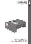
Service Manual
CPAP Respiratory Therapy Device
from serial number J10B5432 to J10E106064
Contents
1
Symbols in service manual...............................................................................................3
2
Safety information............................................................................................................3
3
Preparation of devices when changing patient.................................................................4
4
4.1
4.2
Description of device........................................................................................................5
Housing, display and control elements...............................................................................5
Controller circuit board V3.0..............................................................................................6
5
Technical explanations.....................................................................................................8
6
Tools and measuring equipment....................................................................................10
7
Opening the device........................................................................................................10
8
8.1
8.2
8.3
8.4
8.5
8.6
8.7
8.8
Servicing hardware.........................................................................................................11
Cleaning..........................................................................................................................11
Filter................................................................................................................................11
Checking heating cable...................................................................................................11
Checking plug connections..............................................................................................11
Checking function of display............................................................................................11
Checking display contrast................................................................................................11
Checking key functions....................................................................................................11
Checking for secure attachment of controller circuit board...............................................11
9
Closing the device..........................................................................................................12
10
Checking electrical safety..............................................................................................12
11
11.1
11.2
Servicing software . .......................................................................................................12
Validation of settings........................................................................................................12
Service and analysis........................................................................................................12
12
Final steps......................................................................................................................13
13
Spare parts list...............................................................................................................14
14
14.1
14.2
14.3
Disposal.........................................................................................................................15
Device.............................................................................................................................15
Packaging.......................................................................................................................15
Batteries..........................................................................................................................15
-2-
1 Symbols in service manual
Important information is denoted by symbols in this service manual. Be sure to follow these instructions in order to avoid accidents, personal injury and material damage.
In addition, the local accident prevention regulations and general safety regulations in force in the
area of use must be observed.
This symbol denotes general safety instructions. Follow these instructions to avoid accidents,
personal injury or material damage.
This symbol denotes hazardous situations that may lead to moderately severe injuries.
This symbol denotes situations that may lead to material damage or damage to the device.
This symbol denotes information, tips and instructions for the effi cient, error-free use of the
device.
2 Safety information
•• Before starting maintenance, read this service manual through carefully.
•• There is a risk of short-circuiting due to the capacitors present in the device
(including when de-energized). When servicing is performed at the patient's
home, the patient should be warned of the risk.
•• Repair and maintenance may only be carried out by qualified, authorized and
competent specialist personnel.
•• This manual refers solely to the point respiratory therapy device. It does not deal
with accessories such as therapy tubing and masks.
•• If an accessory is suspected of being defective, it should be visually inspected by
the service technician and the result recorded in the servicing report.
•• For hygiene reasons, we recommend wearing disposable gloves whenever working on the device. Before further work, the device must be subjected to wipe
disinfection with a standard disinfectant solution.
•• When new goods are received by the Service department, the documents supplied with the device must be checked. Devices contaminated are prepared
according to the point hygiene concept.
-3-
3 Preparation of devices when changing patient
The hygienic preparation of a device during a patient change can be carried out using a mechanical
procedure based on the hygiene concept. The type and scale of the preparation are described in
detail in this concept. The number of preparation cycles is not limited.
-4-
4 Description of device
4.1 Housing, display and control elements
Sealing ring1
Keyboard and display
Locking mechanism
for humidifier1
Therapy tube
connection
Contact sockets for humidifier1
Controls for humidifier1
Figure 1:Front view of device
Pressure balance aperture (grid covered)
24 V DC connection
J10E6061
RS232 interface
Rating plate
Filter or connection port for the filtersystempoint
Figure 2:Rear view of device
Display
1
Programing keys
ON/OFF key
Enter key
Figure 3:Keyboard and display
1 optional equipment version
-5-
4.2 Controller circuit board V3.0
DC-Input
Serial interface
Battery contact
Battery contact
CPU
ATmega2561 P5
Quartz
(CPU)
Alarm
generator
Quartz (clock)
IC (clock)
Display
Plug connection for
membrane keyboard
Plug connection for
humidifier electronics
Figure 4:Controller (solder side)
The controller circuit boards V2.0 and V 3.0 are functionally identical. Only the mounting
architecture and the plug connector for the humidifier electronics are different constructed.
-6-
IC (RS232)
Serial interface
24 V DC-input
Fuse
Motor control
connection
Motor voltage
connection
Battery contact
Battery contact
Pressure sensor
on PC24-board II
Backup battery
for internal clock
Figure 5:Controller (component side)
-7-
5 Technical explanations
Patient,
Respiratory
mask
Humdifier
(optional)
point
device
Blower
box
Pressure
Sensor
Load
management
Blower
PI controller
Motor
D/A
converter
Motor
controller
CPU
Display
Flash
RAM
EEPROM
ADC
external
EEPROM
Keyboard
DC power
supply unit
RS232
RCI
AC mains
Battery
Figure 6:Block diagram
Heating (optional when humidifier is connected)
The humidifier heating consists of a heating element in the electronic unit of the humidifier. The
heating capacity can be set to 5 different heating levels using the controls.
The maximum temperature of the heating plate is limited to 60 °C. In addition, there is a thermal
fuse in the electronic unit of the humidifier, which trips at a temperature of 135 °C in the event of a
fault.
Power supply
The device is operated via an external switched-mode power supply with a wide input range of
100 - 240 V AC and a frequency of 50 - 60 Hz.
No maintenance or repairs should be performed on the switched-mode power supply.
-8-
Motor control
A piezoelectric sensor (differential pressure measuring procedure, measuring range: 0 ... 3500 Pa)
continuously measures the actual output pressure. The setpoint pressure value is output by the
computer. The difference between these two values is corrected by the PI controller and the motor
control. Switching controllers are used to minimize power losses.
Motor
DC motor, operating voltage 4 - 24 V, electronically commutated
Adjustment range: 7.0 - 17.5 V DC
point processor (ATmega2561)
The ATmega 2561 processor is a microcontroller which is used in all point devices. The key technical data include:
•• 256 Kbyte flash memory
•• 4 Kbyte EEPROM memory
•• 8 Kbyte RAM
•• programmable interface
•• an integrated A/D converter (10 bit)
•• 54 programmable I/O pins
Clock
The point has a real-time clock. The real-time clock is supplied by an internal battery (CR2032),
which offers an operating time of 8 to 10 years.
Alarm
Output of an acoustic alarm for wake-up function as well as in the case of absent or excessive
mask pressure.
-9-
6 Tools and measuring equipment
The following equipment is required for servicing:
•• Service manual and maintenance documents
•• Battery pack (powerpackpoint) or point power supply unit
•• Screwdriver (Phillips and slotted) in various sizes
•• Soft brush and Service vacuum cleaner
•• Soft base
•• Auxiliary tool (art. no. 00007939)
•• Therapy tube
•• Flow resistor (art. no. 00007303)
•• RS232 adapter cable (Sub-D9 / RJ45 art. no. 00005232)
•• Device for testing electrical safety (e.g. SECUTEST SIII/DIN EN 62353:2008)
•• PC with following system requirements:
––
––
––
––
––
––
––
––
––
––
MS Windows® 98, 2000, NT4.0, ME, XP, Server 2003, Vista or 7
AMD Athlon/Pentium class (x86), clock frequency 700 MHz
min. 192 MB system memory for MS Windows® 98, NT4.0, ME
min. 400 MB system memory for MS Windows® 2000, XP, Server 2003, Vista
min. 150 MB free hard drive space (or more depending on the required storage
capacity for patient files)
min. 280 MB free hard drive space for the Microsoft .NET Framework 2.0
Redistributable (x86)
2 MB graphics card min. High Color (16 bit)
Mouse
1 free COM interface per device
1 free SD interface (only when using DATA box)
•• HOFFRICHTER TRENDset PC software
•• Spray disinfectant (e.g. Mikrozid® Liquid)
7 Opening the device
To protect against germs the surface of the device and, where present, the humidifier must be
treated with a disinfectant immediately after unpacking.
1. Unplug the mains plug.
2. Remove the filter or the filter system filtersystempoint (optional).
3. Remove the humidifier, where present.
4. Remove the two batteries (powerpackpoint), where present.
5. Place the device top down on a soft base.
6. Open the device as follows:
a. Remove the feet of the housing.
b. If the point is set up for the connection of a humidifier, remove the control electronics of the
humidifier and disconnect the plug connection.
c. Release the four screws at the housing.
d. Dismantle the upper casing of the housing.
6. Disconnect the plug connection and the pressure measuring connection.
7. Carefully remove the heating cable (using aids if necessary).
- 10 -
8 Servicing hardware
8.1 Cleaning
1. Clean the inside of the device carefully using the brush and the Service vacuum cleaner.
2. Remove heavy soiling using a damp cloth.
3. Perform spray disinfection on all components acting as air ducting.
4. If a humidifier is present, wash out the water container and perform spray disinfection on it.
Apply a 5 % solution of vinegar to stubborn limescale.
8.2 Filter
Replace the filter with a new one. When using the optional filter system (filtersystempoint), replace
the filter inserts.
8.3 Checking heating cable
1. Check that the heating cable is still intact (insulation) and that the plug connections are not
bent.
2. The heating cable should be protected from tension, compression and clamping.
8.4 Checking plug connections
Check all plug connections on the controller circuit board for secure positioning and, where necessary, correct deficiencies.
The device is energized during the following operations!
8.5 Checking function of display
1. Connect the device to the power supply.
2. Check whether all characters are shown completely and correctly in the display.
8.6 Checking display contrast
1. Press any key. The display lights up with a brightness of 100 %.
2. The background of the display is illuminated. The display should be clearly legible in daylight.
3. After 15 seconds the display fades to 50 % of the brightness level.
4. The display should now be faint, yet still clearly legible.
5. If required, the display contrast can be adjusted with P5 (see Figure 4 on page 6).
8.7 Checking key functions
1. Check that the turbine switches on and off properly when the ON/OFF key is pressed.
2. Check whether the menu can be operated properly using the arrow keys.
8.8 Checking for secure attachment of controller circuit board
Check whether the controller circuit board is properly secured and in the correct position.
- 11 -
9 Closing the device
1. Unplug the mains plug.
2. Position the motor cable in the space between the motor and the wall of the housing and run
the heating cable between the box and the wall of the housing.
3. Position the pressure measuring tube above the controller circuit board and connect it to the
pressure sensor.
4. Carefully fit the upper case of the housing, making sure that no cables or tubes are compressed or crushed.
5. Place the device upright again and screw the upper and lower casing together. Then reattach
the housing feet.
6. If the point was set up for the connection of a humidifier, install the controls and the control
electronics of the humidifier.
7. Insert the filter or fit the filtersystempoint filter system (optional).
10 Checking electrical safety
The point basic device is equipped with protective insulation and does not have any exposed
electrically conductive parts at the housing. As such, electrical safety testing of the device is not
included.
Electrical safety testing is only possible on the power supply unit and is performed by a device
safety tester (e.g. SECUTEST SIII), which complies with the DIN EN 62353:2008 standard. The reference point is the ground conductor on the secondary side of the power supply unit (external contact).
11 Servicing software
11.1 Validation of settings
1. Connect the device to the PC using the adapter cable (art. no. 00005232).
2. Insert the power supply unit and connect it to the device.
3. Start the TRENDset PC software.
4. Compare the settings with the medical prescription, the patient ID card, etc.
5. Correct the values if necessary.
11.2 Service and analysis
1. Connect the therapy tube.
2. Insert the flow resistor (art. no. 00007303) into the other end of the therapy tube.
3. Disable the softstart ramp and the mask test in the complete menu of the device or using
TRENDset.
4. Log in to TRENDset under “Settings / Service / Log in”.
5. Enter “service” as the Username.
6. Enter “user140372” as the Password.
7. Select the view “Times and Counters”.
8. Set the Service counter to the next maintenance interval.
9. Correct the date and time if necessary.
10. Select the menu item “ADU Test”.
- 12 -
11. Start measurement.
12. The entire pressure range is now checked for pressure deviations. The maximum deviation
must not exceed ± 0.5 hPa. If the maximum deviation is exceeded, send the device in to your
distributor for checking.
13. Close the “ADU Test” window.
12 Final steps
After finishing servicing, draw up a final report and affix a test seal showing the date and tester’s initials to a suitable position on the device.
- 13 -
13 Spare parts list
Device
Designation
Power supply unit, 2-pin
Article no.
0000 2020
Power supply cable
3110 0015
Carrier bag
0000 2111
Standard coarse filter 45 x 25 x 7 mm
0000 2110
Therapy tube without measuring tube
0000 7875
Plastic ring (air outlet)
4210 0714
Blower
4100 0109
Controller circuit board without heating cable
0000 5412
Display
1520 0012
Heating cable assembled, SN J10B5432 - J10C5769 or higher, Controller V2.0
0000 5239
Heating cable assembled, J10C5770 or higher, Controller V3.0 and V8.0
0000 5238
Battery CR2032
1600 0011
Ceramic microfuse 2.5 A
2400 0020
Battery contact for powerpackpoint battery pack
0000 2230
Upper casing
0000 5666
Plastic foil keyboard
2200 0096
Air outlet
4210 0728
Bellow air outlet
4210 0713
Cover (instead of control electronic aquapoint )
4210 0708
Clamp (meander)
4210 0715
Noise absorber
4210 0711
Blind DC input, PC interface
4210 0724
Blind DC input, PC interface
4210 0720
Foot for housing
4210 0719
Tab. 1: Spare parts list for device
Humidifier
Designation
aquapoint humidifier incl. control electronic, locking mechanism and sealing ring
Article no.
0000 7949
Control electronic for aquapoint humidifier
0000 4286
Locking mechanism for aquapoint
0000 2361
Sealing ring (air outlet) for aquapoint
4210 0727
Water container with heating plate
0000 4283
Closing cap
4210 0701
Air guide
4210 0703
Tab. 2: Spare parts list for humidifier
Battery pack
Designation
Article no.
0000 7846
powerpackpoint battery pack (2 pcs.)
Tab. 3: Spare parts list for battery pack
- 14 -
Filter system
Designation
Filter system filtersystempoint with coarse and fine filter, ready for use
Filter cassette for filter system filtersystempoint without filter
Article no.
0000 7847
4210 0729
Fine filter for filter system filtersystempoint
00002109
Coarse filter for filter system filtersystempoint
0000 2108
Tab. 4: Spare Parts List for Filter System
14 Disposal
Proper disposal saves natural resources and prevents harmful substances being released into the
environment.
14.1 Device
The device must not be disposed of with the household waste. Please contact the manufacturer to
find out how to dispose of the device, etc. properly.
14.2 Packaging
The packaging is taken back by the manufacturer but it can alternatively be disposed of separately
with the normal household waste.
14.3 Batteries
Exchanged batteries must be recycled in accordance with battery regulations. Please contact the
manufacturer to find out how to dispose of the batteries properly.
HOFFRICHTER GmbH
Mettenheimer Straße 12 / 14
19061 Schwerin
Germany
Telefon: +49 385 39925 - 0
Telefax: +49 385 39925 - 25
E-Mail: [email protected]
www.hoffrichter.de
point 2.0-3.0-service-eng-310811-01
- 15 -