1
point
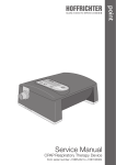
Service Manual
CPAP - Respiratory Therapy Device
Table of Contents
1
Symbols used in the Service Manual........................................................................................3
2
Safety Instructions....................................................................................................................3
3
Preparing the Devices for a Different Patient.............................................................................3
4
Block Diagram...........................................................................................................................4
5
Technical Explanations..............................................................................................................5
6
Tools and Measuring Means......................................................................................................6
3
Opening of the Device...............................................................................................................6
4
4.1
4.2
4.3
4.4
4.5
4.6
4.7
4.8
4.9
Service-Works Hardware...........................................................................................................7
Cleaning.....................................................................................................................................7
Filter Cassette............................................................................................................................7
Controlling Heating Cable...........................................................................................................7
Controlling Plug Connectors.......................................................................................................7
Controlling Display......................................................................................................................7
Controlling Display Contrast and Brightness . .............................................................................7
Controlling Key Function.............................................................................................................7
Controlling Fixing of Controller Board..........................................................................................8
Adjustment . ..............................................................................................................................8
5
Reassemble Device...................................................................................................................8
6
Controlling Technical Safety Aspects........................................................................................8
7
7.1
7.2
Service-Works, Software ..........................................................................................................9
Correct Adjustments...................................................................................................................9
Service and Analysis...................................................................................................................9
8
Final Works................................................................................................................................9
9
9.1
9.2
9.3
Controller ...............................................................................................................................10
Controller point (Front Side)......................................................................................................10
Controller point (Back Side)......................................................................................................11
Adjustment instructions............................................................................................................12
-2-
1 Symbols used in the Service Manual
In this Service Manual, the most important notes for users are indicated by symbols. Please make sure to
follow these hints in order to avoid personal injury or property damage.
Furthermore, all local accident prevention and general safety rules applicable to the intended use should
be followed.
This symbol denotes general safety instructions. Follow these instructions to avoid accidents,
personal injury or material damage.
This symbol denotes hazardous situations that lead to serious injuries or death.
2 Safety Instructions
•• Thoroughly read this service manual before beginning with the maintenance works
•• There is a risk of a short circuit (even in a de-energized state) due to the capacitors in
the device.
•• Repair and maintenance works must only be carried out by qualified, authorized and
skilled people.
•• In case of service works in the domestic area of a patient, the latter has to be warned
against the potential hazard.
•• For hygienic reasons, it is recommended to wear disposable gloves for any work carried out on the device.
•• Please disinfect the device by means of a customary solution before you start work.
3 Preparing the Devices for a Different Patient
A mechanical procedure based on a hygiene concept allows for the recycling of devices, under good
hygienic conditions, which are intended for use in the treatment of different patients. The hygiene concept
provides a detailed description of the required type and rate of recycling. There is no limit on how often a
device can be recycled.
-3-
4 Block Diagram
Patient,
Therapy mask
Humdifier
(optional)
Box
Pressure
Sensor
Power
Management
Blower
PI Controller
Motor
D/A
Converter
Motor
Controller
CPU
Display
Flash
RAM
EEPROM
ADC
external
EEPROM
Key Pad
DC-Power
Supply Unit
RS232
RCI
AC Mains
Battery
Figure 1: Block diagram
-4-
5 Technical Explanations
Heating (optional, if the humidifier is connected)
The humidifier consists of heating controller and heating plate. The humidifier result is adjustable by the
heating power and heating temperature.
For safety reasons the maximum temperature is limited to 60 °C. Additionally below the heating plate a
non reversible thermal fuse is mounted which switches off the heating power at over 135 °C.
Power supply
The device is provided with energy by an external switch mode power supply unit with a wide range
power supply at 100V - 240 V (AC) with the frequency of 50 Hz - 60 Hz. Maintenance and repair works are
not allowed for the power supply unit of the point system.
Motor control unit
A high quality difference pressure sensor (measuring range: 0 ... 3500 Pa) measures continuously the
present pressure at the air outlet. The nominal pressure is given out by the micro processor. The difference between these two values is the input for a PI-controller which controls the motor control unit.
Motor
DC-motor: Operating voltage 4 - 20 V electrical commuted
Control-range:7.0 - 17.5 V DC
Processor point (ATmega.32)
The processor is an 8-bit-micro-controller with a R232-Interface for data transfer. The micro-controller
has an A/D-converter for pressure measurement and a D/A-converter for the nominal pressure output.
The software is protected by a watchdog.
The micro-controller processes the data from the pressure sensor, the keys and the clock. Corresponding
to this the micro-controller gives the necessary information to the motor control unit, the display and the
alarm unit.
Clock
The point device is equipped with a clock (power reserve 8 years).
-5-
6 Tools and Measuring Means
Following equipment are necessary for service/maintenance of the point device:
1. Screwdrivers in different sizes and special tool
2. Compressed air spray
3. Blind plug with measuring tube
4. Therapy tube
5. RS232 adapter cable (SubD9 / RJ45)
6. Voltmeter
7. Pressure measurement device
8. Accumulator, DC power supply unit minimal 24 V, 4 A, DC
9. T
esting device for electrical safety of the power supply unit
(e.g. EN 60601)
10. Laptop or PC
11. TRENDset Software
12. Disinfection spray
13. Soft pad
3 Opening of the Device
1. Unplug mains plug.
2. Take off humidifier module (if existing).
3. Take out filter or filter box (if existing).
4. Lay device upside down on a soft underlay.
5. Open device:
a. Remove the stoppers
b. Remove the screws
c. Remove of the cover (humidifier operation electronics)
d. Unplug the connector
6. Plug off the heating cable connector from the controller board.
-6-
4 Service-Works Hardware
4.1 Cleaning
1. Clean the inner parts of the device by using compressed air.
2. If necessary remove dirt with a moistened cloth.
3. Clean and disinfect humidifier if existing.
4. Disinfect all parts which have had contact with the therapy air.
4.2 Filter Cassette
Renew the standard filter or optional the filter system (filtersystempoint).
4.3 Controlling Heating Cable
1. Control whether isolation and contacts are OK.
2. Heating cable should be protected against traction and squeezing.
4.4 Controlling Plug Connectors
Control all plug connectors and if necessary correct them.
During the following works, the device is energized.
4.5 Controlling Display
1. Connect the device with the mains.
2. Control whether all letters are shown correctly in the display.
4.6 Controlling Display Contrast and Brightness 1. Select “Brightness 100%” by the menu or PC software.
2. During daylight the display should be readable well.
3. If necessary correct the contrast by using P5.
The display brightness of point dims after 15 seconds to the last adjusted brightness, if no operation.
4.7 Controlling Key Function
1. Control whether device can be switched on and off by using the ON/OFF key.
2. Control whether menu can be operated correctly by the operating keys.
-7-
4.8 Controlling Fixing of Controller Board
Control whether the controller board is in the correct place.
4.9 Adjustment For the different adjustments please use the measuring points and the potentiometers as shown and indicated in the Figure 2 and Figure 3.
1. A
djustment of the zero-point
2. Adjustment of the set point pressure / voltage
3. Adjustment of the motor voltage
5 Reassemble Device
1. Switch off the device.
2. Unplug the device.
3. P
ut the cable of the humidifier between blower box and casing. Put on the bottom carefully and
make sure that no cables or tubes are squeezed.
4. Screw on the case.
5. Insert the filter.
6 Controlling Technical Safety Aspects
Several different safety norms, regulations and laws are in force. Additionally different safety test devices
are available. So in the following only the general testing procedure for the European market is described.
Please inform yourself about your national safety requirements. Testing device according to EN 60601 is
necessary (in EU only).
-8-
7 Service-Works, Software
7.1 Correct Adjustments
1. Connect the device to a PC or Laptop by using the adapter cable.
2. Connect the device to the mains voltage supply and switch the device on.
3. Start TRENDset software.
4. Correct adjustments if necessary.
7.2 Service and Analysis
1. Connect therapy circuit.
2. Put the flow resistance into end of the therapy circuit.
3. Switch off soft start and mask test by the device menu.
4. Click “Settings” > “Service” > “Log in”
a. Enter the user name: “service”
b. Enter the password: “user140372” (keep the password confidentially!)
5. Click button “Times and Counters”.
6. If requested change the service counter times.
7. If necessary give in the correct date, time and wake up alarm time.
8. Click “ADU Test”.
9. Start measurement.
10. Now the device does a self testing of all possible pressures. Again the maximum deviation should be
below the red line.
11. End “ADU Test”.
8 Final Works
If necessary or requested write down a test protocol.
-9-
9 Controller
9.1 Controller point (Front Side)
P5: Display contrast
Figure 2:P5 Display contrast
- 10 -
9.2 Controller point (Back Side)
P2: Adjusment of motor voltage (MP3 – GND)
P1: Adjusment of pressure target (MP4 - GND)
P4: Adjusment of motor voltage (MP3 – GND)
P3: Amplification for pressure sensor (MP1 - GND)
Figure 3:Controller (Back Side)
- 11 -
9.3 Adjustment instructions
Zero point adjustment of pressure sensor
1. Connect a voltmeter between MP1 and GND.
2. Adjust by P4 (PC24) 0 V (±15 mV).
Amplification for pressure sensor
1. Connect the therapy tube with point.
2. Dummy plug (4 mm) with pressure measurement tube to be connected at the end of the therapy
tube.
3. External pressure measurement system to be connected at the pressure measurement tube.
4. 13.5 hPa pressure to be adjusted at the point.
5. Start of air compressor.
6. 13.5 hPa pressure to be adjusted at the external pressure measurement system by P3 (PC24)
7. Measure the voltage at MP1.
8. Adjust at MP4 by using P1 the same voltage as rough setting as measured at MP1.
9. Fine adjustment by pc software through ADU test (tolerances + 0.2 hPa) .
Adjustment of motor voltage
1. Adjustment of motor voltage by using TRENDset PC software.
2. Select “ADU test” and adjustment of 14 hPa.
3. Connect voltmeter between MP2 and GND.
4. Adjust by using P2 the same voltage as measured with the voltmeter in the PC software.
Adjustment display contrast
Adjust by using P5 on the front side.
HOFFRICHTER GmbH
Mettenheimer Straße 12 / 14
19061 Schwerin
Germany
Telefon:+49 385 39925 - 0
Telefax:+49 385 39925 - 25
E-Mail: [email protected]
www.hoffrichter.de
point-service-eng-0410-04