1
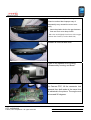
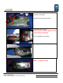
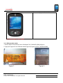
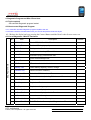
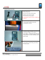
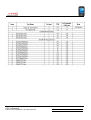
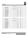
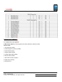
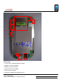
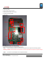
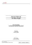
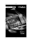
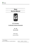
Service Manual for Prophet HTC Proprietary Confidential Treatment Requested Rev. A02 Jan,2006 HTC confidential © 2004, HTC Corporation. All rights reserved. TOTAL 71 CONT.ON. 2 PAGE NO. 1 HTC Corp. Engineering Mobility TITLE: Service Manual REV. NO. DATE CONTENTS DEP. REVISED First Draft Technical Support HB Chen Modify Hard reset mode and enter bootloader mode description Technical Support HB Chen A01 Nov, 29, 2005 A02 Jan,09,2006 APP´D STGE.PER. HTC confidential © 2004, HTC Corporation. All rights reserved. TOTAL 71 CONT.ON. 3 PAGE NO. 2 Table of contents 1. INTRODUCTION ······················································································ 5 1-1. PRODUCT SPECIFICATION ··································································· 5 2. EXPLODED DIAGRAM·············································································· 9 3. ASSEMBLING AND DISASSEMBLING ························································ 11 3.1 DISASSEMBLING ······································································· 11 3.2 ASSEMBLING ··········································································· 19 3.3 LCM ASSEMBLY NOTICE …………………………………………..24 4. DIAGNOSTICS PROGRAM AND WINCE TEST ITEM ·································· 24 4.1 TOOLS REQUIRED ····································································· 24 4.2 HOW TO ENTER DIAGNOSTIC ····················································· 24 4.3 LIST OF DIAGNOSTICTEST / WIN CE TEST ITEM ························· 24 4.4 TEST ITEM OPERATION······························································ 25 5. MAIN BATTERY RE-CERTIFY PROCEDURE ·············································· 26 5.1 FLOW CHART ··········································································· 27 5.2 MEASUREMENT PROCEDURE ···················································· 28 5.3 BATTERY RUNDOWN TEST ······················································· 31 6. Leakage current measurement …………………. …………………. 33 7. COSMETIC INSPECTION CRITERIA ·························································· 37 6.1 DEFINITION OF COSMETIC STANDARD ········································ 37 6.2 VISUAL INSPECTION REQUIREMENTS ········································· 37 6.3 DEFINITON OF INSPECTION DEFECTS AND AREAS ······················· 37 6.4 COSMETIC CRITERIA TABLE ······················································ 38 8. OS, GSM ROM IMAGE REFLASH PROCEDURE ······································ 39 9. FTA (FAULTY TREE ANALYSIS) ····························································· 50 10. SPARE PART LIST ·············································································· 56 .11PHTO OF SPARE PART·········································································· 57 APPENDIX ································································································ 59 A. CUSTOMER, RETAILER MISJUDMENT ··········································· 59 B. GENERIC LABELING PLAN ··························································· 62 C. RF ANTENNA TEST SPECIFICATION ············································· 63 HTC confidential © 2004, HTC Corporation. All rights reserved. TOTAL 71 CONT.ON. 4 PAGE NO. 3 D. BOARD LEVEL 2.5 REPAIRS ······················································· 65 1. Introduction HTC confidential © 2004, HTC Corporation. All rights reserved. TOTAL 71 CONT.ON. 5 PAGE NO. 4 This manual provides the technical information to support the service activities of Prophet. This document contains highly confidential information, so any or all of this document should not be revealed to any third party. 2. Product Specification Platform • Microsoft Windows Mobile 2005 for Pocket PC Edition– English, Spanish, Traditional Chinese, Simplified Chinese, Italian, Portuguese, German • Dimensions: Main unit :108mm(L) *58mm(W) * 18.1 mm(T) • Weight :150g with battery pack Processor • TI OMAP 850 Memory • Flash ROM: 128MB/256MB • Flash RAM: 64MB mobile Double Data Rate (DDR) LCD Module • 2.8 “240 X320 dots resolution • 64K-color TFT Transflective LCD with white LED back light. • Sensitive touch screen • Support screen rotation battery meter , and key lock icons on the lower right corner of today screen GSM/EDGE functional • Audio codec:AMR,EFR,FR,HR • Tri-band 900/1800/1900MHz, or 850/900/1900 • Internal antenna for tri-band GSM • SMS (MO,MT) concatenated SMS (640 characters) • Supplement services ~ Call holding/waiting/forwarding ~ Call barring ~ CLI (Calling Line Identity) ~ Display own number HTC confidential © 2004, HTC Corporation. All rights reserved. TOTAL 71 CONT.ON. 6 PAGE NO. 5 ~ Network selection ~ Cell broadcast ~ Multi-party conference call ~ Spool icon ~ Phase 2+unstructured supplementary ~ Network Lock ~ CPHS DEGE Functionality • EGPRS class B • Multi-slot class 10 • PBCCH • Link Adaptation and Incremental Redundancy • Accept 1.8V and 3V operation • SIM Application Tool Kit release 98 class 3 • Over the Air (OTA) programming • FND • AND • SDN • Security PIN 1&2 SIM Stylus • Lock type mechanism Keyboard/button/switch • One power button • One voice dial/voice record (long press) on the same key • One volume control button (up and down) • One Camera capture (portrait mode default) • One 5-way navigation Pad • Send/Hands-free button • End button • 2 AP buttons (Start or Portal (by operator request)-left button, OK-right button) Notification • One bi-color LED (Green and Red) LED for GSM standby, GSM message, GSM network status, notification ,and charging ststus HTC confidential © 2004, HTC Corporation. All rights reserved. TOTAL 71 CONT.ON. 7 PAGE NO. 6 • Blue LED for Bluetooth notification . • Notification by Sound and Message on the display • Vibrator for notification Audio • Built-in Microphone, • Receiver • Speaker • Loud speaker for hands-free support • Full duplex • Audio sampling rate 16-bits with 8KHz, 11KHz, 16KHz, 22KHz, 44.1KHz, • AMR/AAC/WAV/WMA/MP3 stereo Camera • Color CMOS VGA/1.3/2.0Mega-Pixel camera with macro • Preview Mirror Power • Battery ` Removable rechargeable Lithium Ion Polymer battery, 1200mAh (Typical) ` Charging time: less than 4 hours Battery life: ` WMA:12 hours (Magneto test case) ` WMV:8 hours (Magneto test case) ` Talk time : 3.5~5 hours (at nominal RF Tx power level) ` Standby time: 150~200hors • AC Adapter ` AC input: 100 ~ 240 Vac, 50/60Hz ` DC Output voltage: 5V and 1A Interface • Infrared Port IrDA SIR • One Audio Jack (2.5ψ) • 1.8V and 3V SIM card • One SDIO/MMC card slot • One External antenna connector • One Mini USB connector HTC confidential © 2004, HTC Corporation. All rights reserved. TOTAL 71 CONT.ON. 8 PAGE NO. 7 Device to Device connectivity Bluetooth • Compliant with V 2.0 • Class 2 transmit power • Support profiles : • • • V Generic Access V Generic Object Exchange profile V Serial Port Profile V Headset Profile V Object Push Profile V DUN Client Profile V File Transfer Profiler V AV Profiler V PAN Profile V HID Profile V Hands-free Profile Infrared IrDA SIR Mini-USB SDIO/MMC Accessories • Sync. Cable (Mini-USB/USB) • Carrying Case • AC adapter W/ power plug • Car adapter • Car Kit (capable of muting car stereo when incoming call or call proceeding) • Stereo Wired headset-stereo earpiece with microphone • User manual ,quick start guide, sync, software CD • Stereo Bluetooth headset-mono earphone with microphone • Optional Battery (1200mAh) • Car kit w/car stereo mute function • Travel charger (optional) ~Mini-USB ~1 slot for 2nd battery charging HTC confidential © 2004, HTC Corporation. All rights reserved. TOTAL 71 CONT.ON. 9 PAGE NO. 8 • Cradle (optional) Regulatory • R&TTE : EMC/EMI,CEM, Safety • PTCRB • FCC • Microsoft Window Mobile Version 5.0 • USB Certification • WiFi certification Value Added Applications MASD • Photo Album with editing picture capability • Camera capture utility • Camcorder (H.263 and MPEG4 encoder and decoder) • Zip • Polyphonic MIDI Ring tone Engine • SmartDial MSD • MMS with video clip support • Voice dial via device, wire headset , or BT headset • JAVA virtual machine (J2ME CLDC, MIDP 2.0,) • FAX • OMA DRM2.0 • Blackberry e-mail client (operator dependent) • Wireless Modem (IR,USB, Bluetooth) • Key lock ,screen rotation ,and battery meter SW HTC confidential © 2004, HTC Corporation. All rights reserved. TOTAL 71 CONT.ON. 10 PAGE NO. 9 2. Exploded Diagram HTC confidential © 2004, HTC Corporation. All rights reserved. TOTAL 71 CONT.ON. 11 PAGE NO. 10 3. Assembling and Disassembling 3.1 Disassembling Tools needed for Assembling and Disassembling the Prophet. 1. Lens Cleaning Tissue. 2. Philip Screw Driver 000X50 3. Philip Screw Driver 2.5X40. 4. Torex Screw Driver T6X40 5. Tweezers 6. Special Made Plastic Stick. 1 2 3 6 45 Tweezers.(Suggest to use plastic made) 1. Pull up to release the Stylus. 2. Remove the SD Card Filler. 3. Remove the Antenna Insert Rubber. as indicated on the left. 2 3 1 Next, Remove the battery cover by slightly push backward the battery cover . Note : Cover-Battery 74H00564-0XM HTC confidential © 2004, HTC Corporation. All rights reserved. TOTAL 71 CONT.ON. 12 PAGE NO. 11 .Release the Battery P/N: 35H00051-03M Warning: To reduce risk of fire or burns, do not disassemble, crush, puncture, short external contacts, or dispose of in fire or water. Replace only with specified batteries. Recycle or dispose of used batteries properly. Turn left the Philips screw driver and looses the hook of antenna cover. To remove antenna cover Please use Precision Plastic special tool flat (θ) type 1.2 mm and insert in to the two hole as shown on picture. Insert in angle:30 ° Cover-Antenna P/N: 74H00563-0XM HTC confidential © 2004, HTC Corporation. All rights reserved. TOTAL 71 CONT.ON. 13 PAGE NO. 12 Remove the 2 screws for release internal antenna. Next, remove the Antenna; unlock the connector lock with the plastic stick. Antenna P/N :36H00345-01M Next , remove 2 screws to disassemble bezel and housing HTC confidential © 2004, HTC Corporation. All rights reserved. TOTAL 71 CONT.ON. 14 PAGE NO. 13 Next , start disassembly the housing cover Please be noticed that improper way of disassembly may caused the cover worn easily 1. Insert the plastic stick to the gap between front and rear cover deep inside. 2. Move the stick slightly from lower side to upper to release the 6 hooks (3 each at both side) Release all hooks at both side 1Take off the speaker from housing 2.Disassembly housing and Bezel. For Camera FPC, lift the connector lock upwards from both ends at the same time as indicated in the picture. The angle must not exceed 90 degrees. HTC confidential © 2004, HTC Corporation. All rights reserved. TOTAL 71 CONT.ON. 15 PAGE NO. 14 Next, disassembly the speaker connector using tweezers and housing. Speaker P/N:36H00338-00M Next, disconnect switch board and Main board FPC. Next, remove the LCD from MB. 1.Unlock the LCD connector with plstic special tool (hook side) 2.Take out the FPC with plastic tweezers . HTC confidential © 2004, HTC Corporation. All rights reserved. TOTAL 71 CONT.ON. 16 PAGE NO. 15 Remove 2 screws on main board to disassemble main board and bezel assembly. Note that screw P/N is 72H00724-00M. Remove the audio jack holder with plastic tweezers Note that holder P/N is 71H00960-00M Separate the Audio Daughter Board from the Main Board as indicated on the left. Note that Daughter Board P/N is: 51H00320-50M 1. Remove Vibrator from bezel. 2.Remove Spacer on switch board 3.Remove on GASKET switch board 4.Remove gasket on switch board 4 Note those P/N 3 2 1 : 36H00180-00M 2 : 76H00748-00M 3 : 72H00498-00M 4 : 72H00548-00 1 HTC confidential © 2004, HTC Corporation. All rights reserved. TOTAL 71 CONT.ON. 17 PAGE NO. 16 Remove 4 screws on switch board to disassemble switch board and bezel assembly. Note that screw P/N is 72H00724-00M. Next, to separate the LCD from the bezel as indicated on the left. Note that LCM P/N 1 2 is:60H00032-00(Samsung)/60H00037-00 M(Toppoly) Next, Remove the Navigation keypad rubber from the bezel. Note that Navigation key pad Assembly P/N is: 74H00537-01M HTC confidential © 2004, HTC Corporation. All rights reserved. TOTAL 71 CONT.ON. 18 PAGE NO. 17 Remove the Receiver from bezel with plastic tweezers Note that receiver P/N :36H000253-01M Done for disassembly 3-2 Assembling 1.Assembly receiver into its place on the bezel 2. Put the Rubber keyboard on the bezel. Note: there’re 4 guide pins on bezel, so please aim at them when the Rubber keyboard is put on it. LCM assembly : 1-1Insert LCM into its place on the bezel , the angle about 30 degrees . 1-2.Put down LCM . 1 Note: if a new LCD needs to be replaced, please paste two copper foils before assembly 2 2. Put the switch board on Action button and fasten 4 screws as indicated on the left. Torque : 0.5 kg+0.05cm-kg HTC confidential © 2004, HTC Corporation. All rights reserved. TOTAL 71 CONT.ON. 19 PAGE NO. 18 1. Put the gasket on switch board. 2.Put the gasket on switch board 3.Put the spacer on switch board 4. Put the Vibrator into its place on the bezel. Assemble the Audio daughter board on main board and please pay attention on the Antenna location. 1. Put the Holder on audio jack. 2.Fasten 2 screws to fix main board on bezel as indicated on the left. Torque : 0.5 kg+0.05cm-kg 1 1. Press down S/W board FPC connector into the connector of M/B. 2. Insert LCM FPC into M/B connector. 2 HTC confidential © 2004, HTC Corporation. All rights reserved. TOTAL 71 CONT.ON. 20 PAGE NO. 19 1. Insert the speaker connector into the connector of the M/B. 2.Assembly the Camera module 2 1 1. Assembly the housing. 1 2 Please set the volume button on the center before assembly. 2. Set up speaker on housing. Set up the antenna on the top of the unit. Fasten 4 screws on rear side Torque : 1.2 kg+0.1cm-kg HTC confidential © 2004, HTC Corporation. All rights reserved. TOTAL 71 CONT.ON. 21 PAGE NO. 20 Assembly the antenna cover 1 Note:1. insert from the top of hooks 2.then press down the cover 2 1. put the battery into the unit. 2. slightly push forward the battery cover . 1. Insert the Stylus. 2. Insert SD Card Filler into the slot. 3. Insert the Antenna Rubber. as indicated on the left. HTC confidential © 2004, HTC Corporation. All rights reserved. TOTAL 71 CONT.ON. 22 PAGE NO. 21 The assembly procedure is done. The Unit Assembly is done already. 3-3. LCM assembly notice 1. Stick 2 Mylars on the back of the LCM (Mylar P/N: 76H00967-00M) as figure1 2. Apply the copper foil to LCM back side as figure2 (Copper foil P/N: 72H00782-00M) Figure 1 Figure 2 HTC confidential © 2004, HTC Corporation. All rights reserved. TOTAL 71 CONT.ON. 23 PAGE NO. 22 4. Diagnostic Program and Win CE test item 4.1 Tools required SD card with Diagnostic program loaded. 4.2 How to enter Diagnostic Program 4.2.1: Insert SD card with Diagnostic program loaded to the unit. 4.2.2 Press & hold the Camera Button with your Thumb and jab the reset with Stylus. 4.2.3 Release the Stylus but keep pressing the Camera Button until the Boot Loader Screen comes out. 4.3 List of Diagnostic / WinCE Test Items Diag. Program mode No. Item Description Remark 1 SDRAM Test Check SDRAM Size/Write/Read 2 Display Test Test the LCD display quality 3 Touch Test Touch panel calibration test. 4 LED Test Red/green/amber/key LED on/off test 5 Key Test All buttons (Key) press/release test. 6 B.L Test Three levels Backlight test. 7 Timer Test Timer test 8 SD Test SD card read/write/lock/unlock test. 9 Battery Test Check battery capacity, current, voltage A Vibrator Test Test the function of Battery B Checksum Test Calculation ROM checksum Test. C Msys- Fromat Clear call duration (including Talk time and E-user data) D SPK Play Test Playback a simulation wave test. E Rev Play test Playback to Receiver F Hst Play Playback to 3-ring earphone G IntRec- SpkOut Internal record & playback H IntRec- RevOut Internal record & playback with Receiver I IntRec-HstOut Internal record & earphone out J HstRec-HstOut Earphone MIC record & earphone out Upload To For HTC Service Center upload Diagnostic to SD card. SD HTC confidential © 2004, HTC Corporation. All rights reserved. TOTAL 71 CONT.ON. 24 PAGE NO. 23 Win CE 1 USB Test Suggest to test in Windows CE 2 SIR Test Suggest to test in Windows CE 4.4 Test Items Operation How to select test item: Using navigation button -"Up" or "Down" to select the test items How to execute the test program: Press “Action” button to start each of test items. No. 1 Item RAM Test Description Press Action button to process SDRAM test Display Size and read/write test. It will show OK if pass. Stop on fail. Unit prompts for different display page to detect the defect of LCD, lines or dots. First display is Multiple Color, Press Action to Red Color 2 Display Test Press Action to Green Color Press Action to Blue Color Press Action to Dark Color Diag. program mode Press Action to White Color Press Action to Gary Color Press Action to return Test Menu 3 Touch Test Tap the cross mark (+) with stylus on the correct location. Fail if no reaction Action LED: GreenÆ RedÆBlue Bluetooth 4 LED Test Action LED: GreenÆ GSM Action keypad LED 5 Key Test Follow the indication on device to press buttons for test. 6 Backlight Test Press “Action to test LED and brightness level of LCD (three stages), and then return Test Menu. 7 Timer Test Press Action to check if it shows “Test OK”. 8 SD card Test Lock SD card and insert to unit, then remove SD card 9 Battery Teat Check battery capacity, current, voltage A Vibrator Test B Checksum Test Press Action, unit should vibrate, and then press Action to return Test Menu Press Action to calculate ROM checksum. HTC confidential © 2004, HTC Corporation. All rights reserved. TOTAL 71 CONT.ON. 25 PAGE NO. 24 WinCE C Msys-Format Press Action to clear call duration( talk time and end-user data) D Spk Play test Playback to SPK E Rev Play test Receiver Playback test F Hst Play test Earphone Playback test G IntRec Spkout Intel Record and Speak out H IntRec Revout Intel Record and Receiver out I IntRec Hstout Intel Record and Earphone out J HstRec Hstout Earphone Record and Earphone out 1 USB Test Plug USB cable to connect UUT to PC then and check if USB OK or not. 2 SIR Test Use a device that can support SIR function to connect UUT. 5. Main Battery Re-certify Procedure 5.1 Flow Chart HTC confidential © 2004, HTC Corporation. All rights reserved. TOTAL 71 CONT.ON. 26 PAGE NO. 25 Under 3.75V Measure battery voltage ? Above 3.75V Charge to 3.75V above Charge ? Charge fail Fail Voltage check by Ds2760K ? OK Fail Currect check by Ds2760K ? OK Fail ACR check by Ds2760K ? OK Fail Parameter check by Ds2760K ? OK Fail Whole unit charge test OK Fail Whole unit discharge test ? OK Battery is NG Battery is OK HTC confidential © 2004, HTC Corporation. All rights reserved. TOTAL 71 CONT.ON. 27 PAGE NO. 26 5.2 Measurement Procedure Tools requirement: A. Battery testing fixture B. Multi-meter with battery detecting plug C. Win2000 or above OS PC system D. Ds2760K battery testing program. Note: The Ds2760K program needs to installed onto PC in advance. A B Step 1: Main battery voltage check a. To detect battery voltage by multi-meter through battery connector. - + b. The battery voltage will appear on the multi-meter, make sure the voltage >= 3.75V above If the voltage < 3.75V please charge the main battery and then re-check the battery voltage must > 3.75V. Step 2: Parameter check by DS2760K test program a. Contact battery to detect battery parameter by DS2760K program HTC confidential © 2004, HTC Corporation. All rights reserved. TOTAL 71 CONT.ON. 28 PAGE NO. 27 The battery’s core parameter areas as follows: Check address of 30h/31h Must 30h = 93h 31h = 26h If the register address is incorrect, it means that the EEPROM is defective. HTC confidential © 2004, HTC Corporation. All rights reserved. TOTAL 71 CONT.ON. 29 PAGE NO. 28 Step 3 : Whole unit charge test Plug in AC adapter to unit, the charge light must be turn on (Red), If it is failed in charge test, replace another good battery for double check. Step 4 : Whole unit discharge test Unplug AC voltage, the charge light must be off, but the LCD screen must be still on display. If it is failed in discharge test, replace another good battery for double check. HTC confidential © 2004, HTC Corporation. All rights reserved. TOTAL 71 CONT.ON. 30 PAGE NO. 29 If you still have the misgiving for the battery you can execute rundown test to verify. 5.3 Battery Rundown Test Procedure (A) Tool Requirement: (1) Windows 2000 or above (2) Battery Rundown Software (3) USB Cable or Cradle (4) ActiveSync 4.0 or above (B) Please charge your unit to full capacity for battery (4 hours) before doing the test. Step 1: It is required to save powerdetect.exe and model.txt in the same folder under WinCE via ActiveSync. Step 2: It is unnecessary to adjust power management setting by using rundown test program. Step 3: Execute powerdetect.exe under WinCE, it will enter Sleep Mode after one hour and generate a file named powercap.txt log. HTC confidential © 2004, HTC Corporation. All rights reserved. TOTAL 71 CONT.ON. 31 PAGE NO. 30 ÆRecord every two minutes & Brightness is maximum Powercap.txt Benchmark is 72% Step 4: Tap powercap.txt log to check if the rest battery capacity. If under 72%, please replace a new battery. HTC confidential © 2004, HTC Corporation. All rights reserved. TOTAL 71 CONT.ON. 32 PAGE NO. 31 Chapter 6 – Leakage current measurement This is a quick method to measure if any abnormal leakage current on main board which caused high power consumption compare to GOOD main board. (1) Requirement: - Power Supply - Micro-current Meter - Current series JIG - CABLE - Battery JIG Equipment need: A. Power Supply (set at 4 V /1A). B. Micro-Current Meter ( support 0.5mA ~ 1A). B A 2. Fixture needed C. Cable D. Battery with extension cable E. Current series jig.( with black and red cable) C D E HTC confidential © 2004, HTC Corporation. All rights reserved. TOTAL 71 CONT.ON. 33 PAGE NO. 32 3. Connect cable (C) to positive polarity of power supply (A) and current meter (B) 4. Connect cable of fixture( E ) to negative polarity of power supply (A) and current meter (B) Note : black cable to power supply (A) and red cable to current meter (B) 5. Setting is Ready now for testing ( Don’t turn the power on at this moment ) 6.Turn on power supply ( 4V) and current meter ( 2A) Set the unit to : * Flight mode * Turn on Bluetooth Note: Need to put SIM card first on the unit. HTC confidential © 2004, HTC Corporation. All rights reserved. TOTAL 71 CONT.ON. 34 PAGE NO. 33 7. Measure flight mode current Setting display off: startÆsettings-ÆSystemÆbacklight, set the cursor to Power Save , display will be off, in this condition, please check current value on the current meter, Current value must under 65mA, if over, it means M/B failed, please replace M/B for repair. Unit is turn on and no back Light 8. Switch OFF the unit. Unit is turn off and no display 12. Measure power off current Check current value on the current meter, Current value must under 5 mA, if over, it means M/B failed, please replace M/B for repair. HTC confidential © 2004, HTC Corporation. All rights reserved. TOTAL 71 CONT.ON. 35 PAGE NO. 34 Conclusion: If current consumption are passed at both of flight and power off mode, it means M/B is GOOD. If there is any item FAILED at flight or power off mode, it means M/B is failed, please replace M/B for repair. Measurement parameter Measurement mode Measured Current Flight Mode (Idle mode) REMARK Under 65mA MB is good Over Fail, MB need to be futher repaired 65mA Under 5 mA MB is good Over 5 mA Fail, MB need to be futher repaired POWER OFF (Sleeping mode) HTC confidential © 2004, HTC Corporation. All rights reserved. TOTAL 71 CONT.ON. 36 PAGE NO. 35 7. Cosmetic Inspection Criteria 6.1. Definition of Cosmetic Standard B Standard is for refurbishment inspection. 7.2. Visual Inspection Requirements 2.1 Examination of the device shall be made with workbench light turned on. Ambient illumination is to be 1000±20 lux. 2.2 The inspector shall examine the device at a distance of 30cm± 30degrees for approximately 5 seconds. 2.3 If a visual defect is noted, the inspector shall have an additional 7 seconds to closely examine the defect and classify it according the criteria table. 7.3. Definitions of Inspection Defects and Areas Scratch:A linear cut that penetrated beyond the surface of the material. A scratch can be felt by running your finger over it. Dot / Dent:A recessed spot or void in the surface of the material. Lint:A linear foreign object beyond the surface of the LCD Bump:A hump in the surface of material Area I:LCM, Bezel including phone key, APP button, action key and LED lens. Area II:Keyboard, Housing, back side of battery, antenna cover, release button, stylus and side buttons. Area III:Inner side of battery (not include battery), inside of SD connector, inside of USB port inside of Earphone jack and other area marked in the figure below. D: Diameter/ L: Length/ W: Width/ Number: Number of defects/ S: Distance of dot to dot Remark: 1. Crack is not allowed. 2. All dimensions in millimeters.. Area I Area II Area III HTC confidential © 2004, HTC Corporation. All rights reserved. TOTAL 71 CONT.ON. 37 PAGE NO. 36 7.4. Cosmetic Criteria Table B standard Specs Item Bright dot** Dark dot** Dark or Bright line LCM* Scratch + Blue ≦ 2 Red + Green dots 0.1mm< D≦0.3mm Dark dots ≦ 2 2) Total number ≦ 5 1) D < 1mm, S ≧ 10mm Spot 0.3mm Area 3 Total scratch number ≦ 3 2) Total number≦4 1) D < 1mm, S ≧ 10mm Dent 2) Total number≦4 1) D < 1mm, S ≧ 10mm Bump w≦0.1mm 1.0mm≦L≦2.0mm 2) Total number≦4 Total number ≦ 2 Lint 1) L ≦ 3mm, W≦0.254mm Bur 0.03mm<W≦0.01 2) No Hand Scrape 1.0mm≦L≦2.0mm Particle Total number ≦ 3 Breakage on T/P None Scratch Spot Dent Area 1 Bump Bur Bright mark 2) Total number ≦ 3 Stylus 1) D < 0.5mm, S ≧ 15mm Spot Area 2 Dent Bump Bur Bright mark 1) L<7mm, W<0.15mm 2) Total number<3 Protruding over the top of bezel None Deformed/ Missing/ Loosen None 2) Total number ≦ 4 1) D < 0.5mm, S ≧ 15mm 2) Total number ≦ 4 1) L ≦ 3mm, W≦0.254mm Gap between touch panel 2) No Hand Scrape and bezel 1) L ≦ 7mm, W≦0.15mm 2) Total number ≦3 (Skip corner) Gap between bezel and L≦2.5mm W≦0.25mm N≦2 housing Gap Scratch 2) Total number ≦ 3 Scratch 2) Total number ≦ 3 1) D < 0.3mm, S ≧ 15mm 1) L ≦ 3mm, W≦0.2mm IR Cap *Scratch 1) L ≦ 3mm, W≦0.15mm (Refurbishment specs) 1) L ≦ 15mm, W≦0.4mm Scratch 0.1mm< D≦ None B standard Specs Item (Refurbishment specs) Gap < 0.9mm Gap < 0.6mm Buttons on the bezel Button needs to be pressed smoothly Navigation button Button needs to be pressed smoothly Gap between housing and battery, battery and battery Gap < 0.5mm lock 1) D < 0.7mm, S ≧ 15mm Gap surrounding the buttons 1) 0.05mm<Gap <0.6mm 2) Total number≦4 on the side 2) Button needs to be pressed smoothly 1) D < 0.6mm, S ≧ 15mm 1) 0.05mm<Gap <0.6mm 2) Total number≦4 2) Button needs to be pressed smoothly 1) D < 0.6mm, S ≧ 15mm 2) Total number≦4 1) L ≦ 3mm, W≦0.254mm 2) No Hand Scrape 1) L ≦ 3.0mm, W≦0.25mm 2) Total number ≦ 4 ** The total of LCM defect number must be less than 5 counts. ** The total of defected dots (bright dot and dark dots) must be less than 4. HTC confidential © 2004, HTC Corporation. All rights reserved. TOTAL 71 CONT.ON. 38 PAGE NO. 37 8. OS, GSM Image Reflash Procedure System Requirement: -Windows 2000 -USB Cable or Cradle -MTTY.exe -Master Unit with most update Rom Code -64 MB SD/MMC card SD card Caution: The unit must have at least 70% of battery capacity before starting the re-flash process. Charge the battery in advance if necessary. Note : For the master unit, you could prepare it on these following ways: - Take one from Swap unit with most update Rom Code. - Build one first by connecting to customer web for OS Upgrade/ Download Via RUU. Execute RUU : 1. Boot up device into OS mode. 2. Allow USB connections in ActiveSync connection settings. 3. Connect with PC by USB cable. 4. Execute RUU program to re-flash ROM code. HTC confidential © 2004, HTC Corporation. All rights reserved. TOTAL 71 CONT.ON. 39 PAGE NO. 38 1. Check “I understand the action indicated above and have reviewed the Read me” 2. Click “Next” HTC confidential © 2004, HTC Corporation. All rights reserved. TOTAL 71 CONT.ON. 40 PAGE NO. 39 Check “I completed the steps indicated above” Click “Next” Click “Update” Click “Next” HTC confidential © 2004, HTC Corporation. All rights reserved. TOTAL 71 CONT.ON. 41 PAGE NO. 40 Click “Next” HTC confidential © 2004, HTC Corporation. All rights reserved. TOTAL 71 CONT.ON. 42 PAGE NO. 41 Next: Done for ROM code updated HTC confidential © 2004, HTC Corporation. All rights reserved. TOTAL 71 CONT.ON. 43 PAGE NO. 42 Execute hard reset! Press and hold the Camera button+ Comm Manager button, at the same time use the stylus to press the RESET button.until the Following Hard Reset Screen is pop out, " Press Send to restore factory default or press others key to quit " You can press Talk/Send key to do Hard Reset. Camera Button Comm Manager Button Reset Button A. Upload most update code from master unit to SD /MMC card. (You Only need to do this ONCE when New Update is received) Requirement: (1) Mtty.exe tool ver. 116 (2) USB cable (3) Window2000 or above (4) Master unit with most update ROM image 1. Uncheck USB and COM1 in Connection Settings in ActiveSync if you have installed the ActiveSync in your PC and make sure the USB port is available. HTC confidential © 2004, HTC Corporation. All rights reserved. TOTAL 71 CONT.ON. 44 PAGE NO. 43 Set the Unit into Bootloader Mode ( (1) Press & hold the Camera Button with your Thumb and jab the reset with Stylus. (2) Release the Stylus but keep pressing the Camera Button until the Boot Loader Screen comes out ), wait for Serial on display. Message on PDA Screen: 4 Connect the unit to the PC with USB cable or USB cradle, unit display will change to USB, and then open HTC confidential © 2004, HTC Corporation. All rights reserved. TOTAL 71 CONT.ON. 45 PAGE NO. 44 MTTY116.exe to select USB port. 4. Insert 64 MB SD or MMC card into SD slot of PDA Phone 5. On the PC side, Select OK and press ENTER. Following display will be shown: 6. The prompt “USB>” will appear, to UPLOAD then type. USB>r2xd all HTC confidential © 2004, HTC Corporation. All rights reserved. TOTAL 71 CONT.ON. 46 PAGE NO. 45 (Please notice the blank space between r2s and all) Then press ENTER, following display will be shown: HTC confidential © 2004, HTC Corporation. All rights reserved. TOTAL 71 CONT.ON. 47 PAGE NO. 46 Now the upload to SD card is done! Take out the SD card from PDA phone and mark it according to the Language you build for. CAUTION! DO NOT REMOVE THE USB CABLE FROM THE PC OR PDA, FAIL TO DO SO MAY CAUSE DEVICE UNIT FAIL TO BOOT. HTC confidential © 2004, HTC Corporation. All rights reserved. TOTAL 71 CONT.ON. 48 PAGE NO. 47 B. Use Pre-loaded SD card to Re-flash Unit. 1. Insert Pre-loaded SD card to the unit. 2. Reset the unit and enter the bootloader mode, (1) Press & hold the Camera Button with your Thumb and jab the reset with Stylus. (2) Release the Stylus but keep pressing the Camera Button until the Boot Loader Screen comes out. Restore ALL image from SD Press Voice dial Key To start Download Press record button Restore ALL image from SD Press Voice dial Key To start Download Download SD image? Download SD image? Format BINFS success Format BINFS success 3. Once it is done, display will show Restore ALL image from SD Press Voice dial Key To start Download Download SD image? Format FAT success Success Press any key. 5. Take out the SD card and Cold boot the device (unit). 6. Press and hold the Camera button+ Comm Manager button, at the same time use the stylus to press the RESET button.until the Following Hard Reset Screen is pop out, " Press Send to restore factory default or press others key to quit " You can press Talk/Send key to do Hard Reset. HTC confidential © 2004, HTC Corporation. All rights reserved. TOTAL 71 CONT.ON. 49 PAGE NO. 48 Now the upgrade is done! Note: Due to security issue, it is not allowed to re-flash different customer ID. HTC confidential © 2004, HTC Corporation. All rights reserved. TOTAL 71 CONT.ON. 50 PAGE NO. 49 9. FTA (Faulty Tree Analysis) HTC confidential © 2004, HTC Corporation. All rights reserved. TOTAL 71 CONT.ON. 51 PAGE NO. 50 HTC confidential © 2004, HTC Corporation. All rights reserved. TOTAL 71 CONT.ON. 52 PAGE NO. 51 HTC confidential © 2004, HTC Corporation. All rights reserved. TOTAL 71 CONT.ON. 53 PAGE NO. 52 HTC confidential © 2004, HTC Corporation. All rights reserved. TOTAL 71 CONT.ON. 54 PAGE NO. 53 HTC confidential © 2004, HTC Corporation. All rights reserved. TOTAL 71 CONT.ON. 55 PAGE NO. 54 HTC confidential © 2004, HTC Corporation. All rights reserved. TOTAL 71 CONT.ON. 56 PAGE NO. 55 HTC confidential © 2004, HTC Corporation. All rights reserved. TOTAL 71 CONT.ON. 57 PAGE NO. 56 10. Spare Part List Prophet Part List HTC confidential © 2004, HTC Corporation. All rights reserved. TOTAL 71 CONT.ON. 58 PAGE NO. 57 11. Spare Part Photo HTC confidential © 2004, HTC Corporation. All rights reserved. TOTAL 71 CONT.ON. 59 PAGE NO. 58 HTC confidential © 2004, HTC Corporation. All rights reserved. TOTAL 71 CONT.ON. 60 PAGE NO. 59 Appendix A. Customer, Retailer Misjudgment Before attempt repairing the unit, make sure the type of reported failure could be clearly reproduced; otherwise, check with the customer or distributor once again to identify the problem correctly. The following are failure symptoms that are typical by misjudgment No. Item Possibility Main Battery low power exhausted. 1 No Power even the power While Back Light is turned OFF, the surrounding lighting will be reflected on the button is pressed panel and in a dim location, it looks like the unit is turned OFF. According to the Power Management settings, the units will be switched OFF automatically. The battery life depends on the devices being used in SD Card Slot, and 2 Battery discharges quickly frequency of use of the Backlight. These functions consume a lot of energy. Operating with front light ON, or using high-energy consumption devices such as SD Memory Card will drain out the battery pack faster. Using AC adapter that is NOT supplied with the unit. Charging the battery while operating the unit with heavy loadings could cause the temperature inside the unit to build up which could cause the unit stop charging. At 3 Battery cannot be charged this moment, the LED indicator will flash Yellow to notify user that the charging has been stopped. Or the temperature is extremely low will also stop charging. Since the extreme high or low temperature will cause the battery to discharge quickly, it has been designed to cut battery charge below 0℃ and above 35~40℃ to protect the battery pack. 4 5 6 7 Cannot make If the unit could pass the test with Loop back Interface card, the possibility of unit communications via mobile malfunction becomes low. Then the following items could be the reason of phones through exclusive problem such as location, timing, signal strength, service provider’s mixed up, or cable. problem with the mobile itself. Or could be incompatibility issue. Cannot use SD Memory Card Black or White dot on the screen. Touch Screen or Program Card is not being pre-formatted. SD card has been switched to Write Protect mode. Card not inserted completely, or bad contact between connector contacts. For LCD panel’s normal behavior, it is hard to find a panel without any bad pixel. Once the numbers of dots and the distance between them are within the specifications, it is allowed. Could be wrong operation. HTC confidential © 2004, HTC Corporation. All rights reserved. TOTAL 71 CONT.ON. 61 PAGE NO. 60 Buttons are not reacting. Screen not properly aligned with the stylus calibration. Front Light dim, cannot turn 8 ON, or shuts OFF Check the Front Light settings in Power Management settings automatically. 9 10 11 Cannot playback music, No When Battery low, the music playback becomes difficult and the volume could sound or volume is low. become lower. Cannot execute installed application programs Operation is slow in response Could be an incompatible software Could be insufficient memory. Check amount of system memory. Software being used sometimes is not fully compatible with the system. 12 Hang up Execute many application programs simultaneously Software that requires big amount of memory spaces or the system memory is low or the files being used is fragmented. 13 System Memory is enough, Software that requires big amount of memory spaces or the system memory is low but is shows insufficient. or the files being used is fragmented. *Note: Nevertheless, the above symptoms could be solved by a warm boot or cold boot, make sure the warm/cold boot has been executed and try to reproduce the symptom reported. How to perform Warm Boot and Cold Boot: Warm Boot: Reset the unit by pressing reset button. Cold Boot: Execute hard reset! Press and hold the Camera button+ Comm Manager button, at the same time use the stylus to press the RESET button.until the Following Hard Reset Screen is pop out, " Press Send to restore factory default or press others key to quit " You can press Talk/Send key to do Hard Reset. HTC confidential © 2004, HTC Corporation. All rights reserved. TOTAL 71 CONT.ON. 62 PAGE NO. 61 B. Labeling Plan (Generic) B.1 Main unit Regulatory label (on the rear housing of main unit) It includes: Unit IMEI & Barcode Unit Serial Number & Barcode Unit Part Number & Barcode Image file name: MAIN_UNIT_REGULATION Please note: 1. The brand name is shown on Bezel. 2. All bar codes must be code128 symbology. B.2 Definition of Serial Number For S/N: SSYWWPPZZZZZ SS: SITE CODEÆ HT Y: Year Last Digital of the Year. WW: Week Code: 01 ~ 54 PP: Product Code: BE HTC confidential © 2004, HTC Corporation. All rights reserved. TOTAL 71 CONT.ON. 63 PAGE NO. 62 ZZZZZ: Serial Number (00001 ~ 99999) Use Base 10 Label Characteristic: Material: polyester Color: pantone 422c Ink: pantone 425c C. RF Antenna Test Specification HTC confidential © 2004, HTC Corporation. All rights reserved. TOTAL 71 CONT.ON. 64 PAGE NO. 63 HTC confidential © 2004, HTC Corporation. All rights reserved. TOTAL 71 CONT.ON. 65 PAGE NO. 64 HTC confidential © 2004, HTC Corporation. All rights reserved. TOTAL 71 CONT.ON. 66 PAGE NO. 65 D. Board Level 2.5 Repairs A. Components to be replaced I. Main Board: ONLY the following items have been allowed to replace for M/B. Obverse side 1. SD Card Slot (CON3) 2. Audio daughter Connector (CON5) 3. Power Switch (SW1) 4. Capture Switch (SW4) 5. Volume Slide Switch (SW5) 6. Record Switch (SW3) 7. Mini-USB connector (CON6) 8. Audio Jack (ACON1) 9. FUSE (PTC1) HTC confidential © 2004, HTC Corporation. All rights reserved. TOTAL 71 CONT.ON. 67 PAGE NO. 66 CON SW4 5 SW1 SW5 WWCON_SW1 CON3 SW3 PTC 1 CON 6 ACON 1 Reverse side 1. Connector RF, WEDEG (WEDEG CONN1) 2. Speaker connector (ACON2) 3. Battery Connector (PCON1) 4. SIM Card Connector (CON9) 5. LCM connector (CON2) 6. COAXIAL CONNECTOR (WBCON_SW1) HTC confidential © 2004, HTC Corporation. All rights reserved. TOTAL 71 CONT.ON. 68 PAGE NO. 67 7. Reset Key (SW2) 8. Switch board connector (CON7) 9. Gold Cap,0.07F,70ohm, 3.3V (CG1) 10. Camera connector (CON4) 11. MIC (MIC1) WEDEG_CONN 1 WBCON_SW 1 ACON 2 CG 1 CON 4 CON 9 PCON 1 CON 2 CON 7 MIC 1 SW 2 B. Problem Identification & Troubleshooting I. Basic Repair Instructions for Component Replacement: Step 1. Place the solder-proof tape to cover the surrounding area of the components which being replaced. Warning:DO NOT overheat the tape and components to avoid the tape melted and make the component damage. Step 2 Use Heater Gun (HAKO850B, set the temperature between HTC confidential © 2004, HTC Corporation. All rights reserved. TOTAL 71 CONT.ON. 69 PAGE NO. 68 350℃, Air Speed 3~5) to remove the components. Step 3 It has to wait the temperature cool down before the damaged components been removed. Or, the others components could be gone when the solder-proof tape been taken off. Step 4 After the damaged components has been replaced; clean the surroundings for solder and flux residues. II. Main Board: The following items have been allowed to replace for Main Board 1. Recording Switch (SW3), Camera Switch (SW4), Reset Switch (SW2), Power Switch (SW 1) If the switch is broken, warp or doesn’t work properly (measure by scope), replace it. 1.1 If the switch still doesn’t work properly after replace new one, please replace the M/B. 2. Camera FPC Connector (CON4) 2.1 If the connector is broken, warp or doesn’t work properly (measure by scope), replace it. 2.2 If the connector still doesn’t work properly after replace new one, please replace the M/B. 3. Mini-USB Connector (CON6) 3.1 If the connector is broken, warp or doesn’t work properly (measure by scope), replace it. 3.2 If the connector still doesn’t work properly after replace new one, please replace the M/B. 4. Audio Jack (ACON 1) 5.1 If the connector is broken, warp or doesn’t work properly (measure by scope), replace it. 5.2 If the connector still doesn’t work properly after replace new one, please replace the M/B. 5. LCD FPC Connector (CON2) 5.1 If the connector is broken, warp or doesn’t work properly (measure by scope), replace it. 5.2 If the connector still doesn’t work properly after replace new one, please replace the M/B. 5.3 Place solder-proof tape on CON2 to prevent it melted when using heater gun to remove CON2. 6. Switch Board FPC Connector (CON7) 6.1 If the connector is broken, warp or doesn’t work properly (measure by scope), replace it. 6.2 If the connector still doesn’t work properly after replace new one, please replace the M/B. 6.3 Place solder-proof tape on CON6 to prevent it melted when using heater gun to remove CON6 7. Battery Connector (PCON 1) HTC confidential © 2004, HTC Corporation. All rights reserved. TOTAL 71 CONT.ON. 70 PAGE NO. 69 7.1 If the connector is broken, warp or doesn’t work properly (measure by scope), replace it. 7.2 If the connector still doesn’t work properly after replace new one, please replace the M/B. 8. Gold Cap (CG1) 8.1 If the Golden cap function failure (can not keep the date, RTC failure) replace it. Replace process: A. Remove CG1 (DO NOT use Heater Gun to remove) B. Take a new one for replace: Notice: 1. Set up the welding iron temperature 350 degree C 2. Don’t stay on the pins (positive and negative pin) of component (CG1) over 5 seconds. 3. Don’t contact the component body with welding iron directly. 8.2 If the component doesn’t work properly after replace new one, please replace the M/B. 9. SIM Card Connector (CON 9) 9.1 If the connector is broken, warp or doesn’t work properly (measure by scope), replace it. 9.2 If the connector still doesn’t work properly after replace new one, please replace the M/B. 9.3 Use solder iron only to replace new component. DO NOT use Heater Gun to remove component to prevent next connector melted. 10. WEDEG RF connector (WEDEG CONN1) 10.1 If the switch is broken, warp or doesn’t work properly (measure by scope), replace it. 10.2 If the switch still doesn’t work properly after replace new one, please replace the M/B. 11. FUSE (PTC 1) 11.1 If the switch is broken, warp or doesn’t work properly (measure by scope), replace it. 11.2 If the switch still doesn’t work properly after replace new one, please replace the M/B. 12. Volume Control Switch (SW5) 12.1 If the switch is broken, warp or doesn’t work properly (measure by scope), replace it. 12.2 If the switch still doesn’t work properly after replace new one, please replace the M/B. 13. SD Card Slot (CON3) 13.1 If the slot is broken, warp or doesn’t work properly (measure by scope), replace it. 13.2 If the slot still doesn’t work properly after replace new one, please replace the M/B. HTC confidential © 2004, HTC Corporation. All rights reserved. TOTAL 71 CONT.ON. 71 PAGE NO. 70 B. Prophet Part List for Board Level Repair Prophet BOARD LEVEL Spare part List HTC confidential © 2004, HTC Corporation. All rights reserved. TOTAL 71 CONT.ON. F PAGE NO. 71