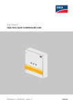
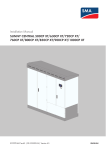
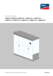
1
Service Manual for Installers
Test Instructions for the Power-Generating Unit Protection Test
SUNNY CENTRAL 500CP XT/630CP XT/720CP XT/
760CP XT/800CP XT/850CP XT/900CP XT/1000CP XT
SCCPXT_EZE-SG-en-12 | Version 1.2
ENGLISH
Legal Provisions
SMA Solar Technology AG
Legal Provisions
The information contained in these documents is property of SMA Solar Technology AG. Any publication, whether in
whole or in part, requires prior written approval by SMA Solar Technology AG. Internal reproduction used solely for
the purpose of product evaluation or other proper use is allowed and does not require prior approval.
SMA Warranty
You can download the current warranty conditions from the Internet at www.SMA-Solar.com.
Trademarks
All trademarks are recognized, even if not explicitly identified as such. A lack of identification does not mean that a
product or symbol is not trademarked.
The BLUETOOTH® word mark and logos are registered trademarks of Bluetooth SIG, Inc. and any use of these marks
by SMA Solar Technology AG is under license.
Modbus® is a registered trademark of Schneider Electric and is licensed by the Modbus Organization, Inc.
QR Code is a registered trademark of DENSO WAVE INCORPORATED.
Phillips® and Pozidriv® are registered trademarks of Phillips Screw Company.
Torx® is a registered trademark of Acument Global Technologies, Inc.
SMA Solar Technology AG
Sonnenallee 1
34266 Niestetal
Germany
Tel. +49 561 9522-0
Fax +49 561 9522-100
www.SMA.de
E-mail: [email protected]
© 2004 to 2015 SMA Solar Technology AG. All rights reserved.
2
SCCPXT_EZE-SG-en-12
Service Manual for Installers
SMA Solar Technology AG
Table of Contents
Table of Contents
1
2
Information on this Document .....................................................................................................
4
1.1
1.2
1.3
1.4
1.5
1.6
Validity ..............................................................................................................................................................
Target Group ....................................................................................................................................................
Additional Information......................................................................................................................................
Symbols.............................................................................................................................................................
Typographies ....................................................................................................................................................
Nomenclature ...................................................................................................................................................
4
4
4
4
5
5
Safety.............................................................................................................................................
6
2.1
2.2
2.3
3
Power-Generating Unit Protection Test....................................................................................... 11
3.1
3.2
3.3
3.4
4
Intended Use..................................................................................................................................................... 6
Safety Information ............................................................................................................................................ 6
Personal Protective Equipment......................................................................................................................... 9
Safety during the Power-Generating Unit Protection Test ..............................................................................
Calculating the Reference Voltage..................................................................................................................
Saving the Test Parameters ..............................................................................................................................
Performing the Power-Generating Unit Protection Test...................................................................................
Disconnecting and Reconnecting................................................................................................. 14
4.1
4.2
Safety When Disconnecting and Reconnecting Voltage Sources................................................................. 14
Disconnecting the Inverter................................................................................................................................ 14
4.2.1
4.2.2
4.2.3
4.2.4
4.3
Switching off the Inverter .................................................................................................................................
Disconnecting the DC Side..............................................................................................................................
Disconnecting the AC Side ..............................................................................................................................
Disconnecting the Supply Voltage and External Voltages ............................................................................
14
14
15
15
Reconnecting the Inverter................................................................................................................................. 16
4.3.1
4.3.2
4.3.3
4.3.4
5
11
11
12
12
Reconnecting the Supply Voltage and External Voltages .............................................................................
Reconnecting the AC Side...............................................................................................................................
Reconnecting the DC Side...............................................................................................................................
Restarting the Inverter ......................................................................................................................................
16
17
17
17
Contact........................................................................................................................................... 18
Service Manual for Installers
SCCPXT_EZE-SG-en-12
3
1 Information on this Document
1
SMA Solar Technology AG
Information on this Document
1.1
Validity
This document is valid for the following device types:
Device type
Production version
OCU firmware
version
DSP firmware
version
SC 500CP‑10 (Sunny Central 500CP XT)
E7
01.80.00.R
01.80.00.R
SC 630CP‑10 (Sunny Central 630CP XT)
SC 720CP‑10 (Sunny Central 720CP XT)
SC 760CP‑10 (Sunny Central 760CP XT)
SC 800CP‑10 (Sunny Central 800CP XT)
SC 850CP‑10 (Sunny Central 850CP XT)
SC 900CP‑10 (Sunny Central 900CP XT)
SC 1000CP‑10 (Sunny Central 1000CP XT)
The production version is indicated on the type label.
The firmware version can be read off from the user interface.
Illustrations in this document are reduced to the essential and may deviate from the real product.
1.2
Target Group
The tasks described in this document must only be performed by qualified persons. Qualified persons must have the
following skills:
• Knowledge of how the product works and is operated
• Training in how to deal with the dangers and risks associated with installing and using electrical devices and
systems
• Training in the installation and commissioning of electrical devices and systems
• Knowledge of all applicable standards and directives
• Knowledge of and adherence to this manual and all safety precautions
1.3
Additional Information
Links to additional information can be found at www.SMA-Solar.com.
1.4
Symbol
Symbols
Explanation
Indicates a hazardous situation which, if not avoided, will result in death or serious injury
Indicates a hazardous situation which, if not avoided, can result in death or serious injury
Indicates a hazardous situation which, if not avoided, can result in minor or moderate injury
Indicates a situation which, if not avoided, can result in property damage
4
SCCPXT_EZE-SG-en-12
Service Manual for Installers
1 Information on this Document
SMA Solar Technology AG
Symbol
Explanation
Information that is important for a specific topic or goal, but is not safety-relevant
Indicates a requirement for meeting a specific goal
Desired result
A problem that might occur
1.5
Typographies
Typographies
Use
Example
• Display messages
bold
• Set parameter WGra to 0.2.
• Elements on a user interface
• Terminals
• Slots
• Elements to be selected
• Elements to be entered
>
• Connects several elements to be
selected
• Select PV system > Detect.
[Button/Key]
• Button or key to be selected or
pressed
• Select [Start detection].
1.6
Nomenclature
Complete designation
Designation in this document
Sunny Central
Inverter
Sunny Central Communication Controller
SC-COM or communication unit
Service Manual for Installers
SCCPXT_EZE-SG-en-12
5
2 Safety
2
2.1
SMA Solar Technology AG
Safety
Intended Use
The Sunny Central is a PV inverter which converts the direct current generated in the PV modules into grid-compliant
alternating current. An external MV transformer fitted downstream feeds the generated alternating current into the
utility grid.
The product is suitable for indoor and outdoor use.
The enclosure complies with degree of protection IP54. The inverter is classified under Class 4C2 as per
EN 60721-3-4 and is suitable for operation in a chemically active environment.
The maximum permissible DC input voltage of the inverter must not be exceeded.
The inverter must only be operated in conjunction with a suitable MV transformer.
• The MV transformer must be designed for voltages that arise during pulsed mode of the inverter.
• For the Sunny Central 500CP XT/630CP XT/720CP XT/760CP XT/800CP XT the maximum voltage to ground is:
±1,450 V
• For the Sunny Central 850CP XT/900CP XT/1000CP XT the maximum voltage to ground is: ±1,600 V
• Do not connect more than one inverter to one winding of the MV transformer.
• The neutral conductor on the low-voltage side of the MV transformer must not be grounded.
You can find further information on suitable transformers in the technical information "Requirements for MediumVoltage Transformers and Transformers for Internal Power Supply for the SUNNY CENTRAL".
Do not deactivate or modify settings that affect grid management services without first obtaining approval from the grid
operator.
Use this product only in accordance with the information provided in the enclosed documentation and with the locally
applicable standards and directives. Any other application may cause personal injury or property damage.
Alterations to the product, e.g. changes or modifications, are only permitted with the express written permission of
SMA Solar Technology AG. Unauthorized alterations will void guarantee and warranty claims and usually void the
operating license. SMA Solar Technology AG shall not be held liable for any damage caused by such changes.
Any use of the product other than that described in the Intended Use section does not qualify as appropriate.
The enclosed documentation is an integral part of this product. Keep the documentation in a convenient place for
future reference and observe all instructions contained therein.
All work on the product must only be performed using appropriate tools and in compliance with the ESD protection
regulations.
Suitable personal protective equipment must be worn by all persons working on or with the product.
Unauthorized persons must not operate the product and must be kept at a safe distance from the product.
The product must not be operated with open covers or doors.
The product must not be opened when it is raining or when humidity exceeds 95%.
The product must not be operated with any technical defects.
The type label must remain permanently attached to the product.
2.2
Safety Information
This section contains safety information that must be observed at all times when working on or with the product. To
prevent personal injury and property damage and to ensure long-term operation of the product, read this section
carefully and observe all safety information at all times.
6
SCCPXT_EZE-SG-en-12
Service Manual for Installers
2 Safety
SMA Solar Technology AG
Danger to life from electric shock due to live voltage
High voltages are present in the live components of the product. Touching live components results in death or serious
injury due to electric shock.
• Wear suitable personal protective equipment for all work on the product.
• Do not touch any live components.
• Observe all warning messages on the product and in the documentation.
• Observe all safety information of the module manufacturer.
• After switching off the inverter, wait at least 15 minutes before opening it to allow the capacitors to discharge
completely (see Section 4.2, page 14).
Danger to life from electric shock due to live DC cables
DC cables connected to PV modules that are exposed to sunlight carry live voltage. Touching live cables results in
death or serious injury due to electric shock.
• Prior to connecting the DC cables, ensure that the DC cables are voltage-free.
• Wear suitable personal protective equipment for all work on the device.
Danger to life from electric shock due to ground fault
If a ground fault has occurred, parts of the PV power plant that are supposedly grounded may in fact be live.
Touching incorrectly grounded parts of the PV power plant results in death or serious injuries from electric shock.
• Before working on the PV power plant, ensure that no ground fault is present.
• Wear suitable personal protective equipment for all work on the device.
Danger to life from electric shock due to damaged product
Operating a damaged product can lead to hazardous situations that result in death or serious injuries due to electric
shock.
• Only operate the product when it is in a flawless technical condition and safe to operate.
• Check the product regularly for visible damage.
• Make sure that all external safety equipment is freely accessible at all times.
• Make sure that all safety equipment is in good working order.
• Wear suitable personal protective equipment for all work on the product.
Service Manual for Installers
SCCPXT_EZE-SG-en-12
7
2 Safety
SMA Solar Technology AG
Danger to life from electric shock even if the inverter is disconnected on the AC and DC sides
The precharge unit of the order option "Q at Night" will carry live voltage even if the AC disconnection unit and the
DC switchgear are open. Touching live components results in death or serious injury due to electric shock.
• Do not touch any live components.
• Switch off the inverter.
• After switching off the inverter, wait at least 15 minutes before opening it to allow the capacitors to discharge
completely.
• Ensure that no voltage is present.
• Do not remove protective covers.
• Observe the warning messages.
• Wear suitable personal protective equipment for all work on the product.
Danger to life from electric shock when entering the PV field
Ground-fault monitoring does not provide protection from personal injury. PV modules which are grounded with
ground-fault monitoring discharge voltage to ground. Entering the PV field can result in lethal electric shocks.
• Ensure that the insulation resistance of the PV field exceeds the minimum value. The minimum value of the
insulation resistance is: 1 kΩ.
• Before entering the PV field, switch the PV modules to insulated operation.
• Configure the PV power plant as a closed electrical operating area.
Danger to life from electric shock if the product is not locked
If the product is not locked, unauthorized persons will have access to live components carrying lethal voltages.
Touching live components can result in death or serious injury due to electric shock.
• Always close and lock the product.
• Remove the keys.
• Store the keys in a safe place.
• Ensure that no unauthorized persons have access to the closed electrical operating area.
Danger to life due to blocked escape routes
In hazardous situations, blocked escape routes can lead to death or serious injury. Opening the doors of two
products located opposite each other can block the escape route. It is imperative that the escape route is freely
accessible at all times.
• An escape route must be available at all times. Make sure the minimum passage width of the escape route
meets local standards.
• Do not place any objects in the escape route area.
• Remove all tripping hazards from escape routes.
8
SCCPXT_EZE-SG-en-12
Service Manual for Installers
2 Safety
SMA Solar Technology AG
Risk of fire due to failure to observe torque specifications on live bolted connections
Failure to follow the specified torques reduces the ampacity of live bolted connections so that the contact resistances
increase. This can cause components to overheat and catch fire.
• Ensure that live bolted connections are always tightened with the exact torque specified in this document.
• When working on the device, use suitable tools only.
• Avoid repeated tightening of live bolted connections as this may result in inadmissibly high torques.
Risk of burns due to hot components
Some components of the product can get very hot during operation. Touching these components can cause burns.
• Observe the warnings on all components.
• During operation, do not touch any components marked with such warnings.
• After switching off the product, wait until any hot components have cooled down sufficiently.
• Wear suitable personal protective equipment for all work on the product.
Property damage due to dust intrusion and moisture penetration
Dust or moisture intrusion can damage the product and impair its functionality.
• Do not open the enclosure during rainfall or when humidity exceeds the specified thresholds. The humidity
thresholds are: 15% to 95%.
• Only perform maintenance work when the environment is dry and free of dust.
• Operation of the product is only permitted when it is closed.
• Connect the external supply voltage after mounting and installing the product.
• If the installation or commissioning process is interrupted, mount all panels.
• Close and lock the enclosure.
• The product must always be closed for storage.
• Store the product in a dry and covered location.
• Temperature at the storage location must be in the specified range. The temperature range is: −25°C to +70°C
.
Damage to electronic components due to electrostatic discharge
Electrostatic discharge can damage or destroy electronic components.
• Observe the ESD safety regulations when working on the product.
• Wear suitable personal protective equipment for all work on the product.
• Discharge electrostatic charge by touching grounded enclosure parts or other grounded elements. Only then is
it safe to touch electronic components.
2.3
Personal Protective Equipment
Always wear suitable protective equipment
When working on the product, always wear the appropriate personal protective equipment for the specific job.
Service Manual for Installers
SCCPXT_EZE-SG-en-12
9
2 Safety
SMA Solar Technology AG
The following personal protective equipment is regarded to be the minimum requirement:
☐ In a dry environment, safety shoes of category S3 with perforation-proof soles and steel toe caps
☐ During precipitation or on moist ground, safety boots of category S5 with perforation-proof soles and steel toe
caps
☐ Tight-fitting work clothes made of 100% cotton
☐ Suitable work pants
☐ Individually fitted hearing protection
☐ Safety gloves
Any other prescribed protective equipment must also be used.
10
SCCPXT_EZE-SG-en-12
Service Manual for Installers
3 Power-Generating Unit Protection Test
SMA Solar Technology AG
3
Power-Generating Unit Protection Test
The power-generating unit protection test is a fundamental part of PV system certification. For existing systems the
protection test is part of the certificate, for new systems it is part of the declaration of conformity. The power-generating
unit protection test helps grid operators and the certifying body to understand the proper parameterization and
function of the protection concept. To this end, the test procedure must be documented completely. The
parameterization specifications and the accuracy class requirements can be found in the grid connection guidelines or
are specified by the grid operator.
3.1
Safety during the Power-Generating Unit Protection Test
Danger to life from electric shock due to live voltage
High voltages are present in the live components of the product. Touching live components results in death or serious
injury due to electric shock.
• Wear suitable personal protective equipment for all work on the product.
• Do not touch any live components.
• Observe all warning messages on the product and in the documentation.
• Observe all safety information of the module manufacturer.
• After switching off the inverter, wait at least 15 minutes before opening it to allow the capacitors to discharge
completely (see Section 4.2, page 14).
3.2
Calculating the Reference Voltage
Contractually agreed voltage VC corresponds to parameter VRtg
The contractually agreed voltage at the grid feed-in point VC corresponds to the parameter VRtg. VC – the voltage
contractually agreed on with the electric utility company – must be entered for the parameter VRtg during
commissioning and calculation of the reference voltage.
An appropriate reference voltage must be selected for the testing device when performing the protection test. The
reference voltage can be calculated using the following formula.
Formula Symbol
Unit
Explanation
V0
V
Reference voltage of testing device
VC
V
Voltage at the grid feed-in point, contractually agreed with the grid operator
i
-
Transmission ratio of the MV transformer. The transmission ratio is the
ratio of TrfVolExLo to TrfVolExHi.
VRtg*
V
Nominal line voltage of the utility grid (parameter)
Service Manual for Installers
SCCPXT_EZE-SG-en-12
11
3 Power-Generating Unit Protection Test
SMA Solar Technology AG
Formula Symbol
Unit
Explanation
TrfVolExLo**
V
Voltage on the low-voltage side of the external transformer (parameter)
TrfVolExHi**
V
Voltage on the high-voltage side of the external transformer (parameter)
* This parameter takes the level of the medium voltage into account. VC, the voltage at the grid feed-in point as contractually agreed with
the grid operator, must be entered for VRtg.
** These parameters take the transformation ratio of the tap changer of the MV transformer into account. During commissioning, the tap
changer is adjusted in such way that the terminal voltage of the MV transformer matches the nominal voltage of the inverter as closely as
possible.
3.3
Saving the Test Parameters
The inverters have two relevant parameter pairs each for voltage increase protection and voltage drop protection and
one relevant pair of parameters for frequency increase protection and frequency drop protection.
Setting value / operating time
Voltage increase protection
1st level: V> / tV>
VCtlhLim / VCtlhLimTm
2nd level: V>> / tV>>
VCtlhhLim / VCtlhhLimTm
1st level: V< / tV<
VCtllLim / VCtllLimTm
2nd level: V<< / tV<<
VCtlllLim / VCtlllLimTm
Frequency increase protection
1st level: f> / tV>
HzCtlhLim / HzCtlhLimTm
Frequency drop protection
1st level: f< / tV<
HzCtllLim / HzCtllLimTm
Voltage drop protection
Access to parameters
The parameters needed for the power-generating unit protection test are only accessible after the installer
password has been entered. The installer password is changed during the initial installation. You can obtain the
changed installer password from the PV system operator. The default password can be found in the operating
manual.
Procedure:
1. Log into the user interface.
2. Select PV system > Devices.
3. Select
.
☑ A list of the existing device types appears.
4. Select the desired device type.
☑ A list appears containing all existing devices of this type.
5. Select the desired device from the list.
6. Select the tab Parameters.
7. Save the test parameter values.
3.4
Performing the Power-Generating Unit Protection Test
Materials required for test:
☐ Three-phase testing device with the following properties:
– Trigger function for monitoring the potential-free contact
– Voltage range up to 530 VAC (line-to-line) with accuracy better than 0.1%
12
SCCPXT_EZE-SG-en-12
Service Manual for Installers
SMA Solar Technology AG
3 Power-Generating Unit Protection Test
– Logging function
☐ Measurement cables
☐ Laptop for changing the inverter parameters
Requirements:
☐ The relevant test parameters have been saved (see Section 3.3, page 12).
☐ The tap changer setting on the MV transformer complies with the specifications of the grid operator or the PV
system certificate.
☐ The parameter settings comply with the specifications of the grid operator or the PV system certificate.
Danger to life due to electric shock or electric arc if live components are touched
• Switch off the inverter and wait at least 15 minutes before opening it to allow the capacitors to discharge
completely.
• Disconnect the inverter (see Section 4, page 14).
Procedure:
1. Identify the measurement and disconnect terminal using the circuit diagram and reference designation.
2. Connect the outputs L1, L2 and L3 of the testing device to the
measurement inputs P1, P2 and P3 on the measurement and
disconnect terminals of the voltage measurement unit.
3. Connect the binary input of the testing device to the measurement inputs P5 and P6 on the measurement and
disconnect terminals of the voltage measurement unit.
4. Connect the testing device to the external voltage supply.
5. Connect the laptop to the service interface.
6. Log into the user interface as an installer.
7. Perform the power-generating unit protection test in accordance with the TR8 data request form. Set the test
parameters in accordance with the specifications of the grid operator or the PV system certificate.
• Voltage increase protection V> / tV> with the parameters VCtlhLim and VCtlhLimTm
• Voltage increase protection V>> / tV>> with the parameters VCtlhhLim and VCtlhhLimTm
• Voltage drop protection V< / tV< with the parameters VCtllLim and VCtllLimTm
• Voltage drop protection V<< / tV<< with the parameters VCtlllLim and VCtlllLimTm
• Frequency increase protection f> / tV> with the parameters HzCtlhLim and HzCtlhLimTm
• Frequency drop protection f<< / tV<< with the parameters HzCtllLim and HzCtllLimTm
8. Remove the measurement cables from the measurement and disconnect terminals.
9. Reconnect the inverter (see Section 4.3, page 16).
Service Manual for Installers
SCCPXT_EZE-SG-en-12
13
4 Disconnecting and Reconnecting
4
SMA Solar Technology AG
Disconnecting and Reconnecting
4.1
Safety When Disconnecting and Reconnecting Voltage Sources
Danger to life from electric shock due to live voltage
High voltages are present in the live components of the product. Touching live components results in death or serious
injury due to electric shock.
• Wear suitable personal protective equipment for all work on the product.
• Do not touch any live components.
• Observe all warning messages on the product and in the documentation.
• Observe all safety information of the module manufacturer.
• After switching off the inverter, wait at least 15 minutes before opening it to allow the capacitors to discharge
completely (see Section 4.2, page 14).
Danger to life from electric shock due to ground fault
If a ground fault has occurred, parts of the PV power plant that are supposedly grounded may in fact be live.
Touching incorrectly grounded parts of the PV power plant results in death or serious injuries from electric shock.
• Before working on the PV power plant, ensure that no ground fault is present.
• Wear suitable personal protective equipment for all work on the device.
Risk of burns due to hot components
Some components of the product can get very hot during operation. Touching these components can cause burns.
• Observe the warnings on all components.
• During operation, do not touch any components marked with such warnings.
• After switching off the product, wait until any hot components have cooled down sufficiently.
• Wear suitable personal protective equipment for all work on the product.
4.2
4.2.1
Disconnecting the Inverter
Switching off the Inverter
1. Turn the key switch to Stop.
2. Remove the key. This will protect the inverter from inadvertent reconnection.
3. Wait 15 minutes before opening the doors. This allows the inverter capacitors to discharge.
4.2.2
Disconnecting the DC Side
1. Switch off the inverter (see Section 4.2.1, page 14).
2. Disconnect all poles of the DC voltage in the DC main distribution or DC subdistribution (see documentation of the
main or subdistribution).
3. Ensure that the DC switchgear in the inverter is open.
4. Ensure that no voltage is present on the load side of the DC switchgear.
14
SCCPXT_EZE-SG-en-12
Service Manual for Installers
SMA Solar Technology AG
4 Disconnecting and Reconnecting
5. Cover or isolate any adjacent live components.
6. Remove the protective covers over the fuses.
7. Remove all fuses and disconnection blades from all fuse holders of the inverters. Use an LV/HRC fuse extractor.
4.2.3
Disconnecting the AC Side
1. Switch off the inverter (see Section 4.2.1, page 14).
2. Disconnect the DC side (see Section 4.2.2, page 14).
3. Externally disconnect the AC voltage of the MV transformer.
4. Switch off the AC disconnection unit in the inverter.
5. Ensure that no voltage is present.
6. Cover or isolate any adjacent live components.
4.2.4
Disconnecting the Supply Voltage and External Voltages
1. If the supply voltage is only to be disconnected upstream from
the circuit breaker, switch the circuit breaker of the supply
voltage off.
2. If the supply voltage is also to be disconnected downstream from the supply voltage circuit breaker, switch the
external circuit breaker of the supply voltage off.
Tip: The external circuit breaker of the supply voltage is usually located in a subordinate distribution station.
3. Disconnect any additional external voltage.
Service Manual for Installers
SCCPXT_EZE-SG-en-12
15
4 Disconnecting and Reconnecting
SMA Solar Technology AG
4. Switch the motor-protective circuit-breakers of the grid
monitoring off.
5. Open the measurement and disconnect terminals.
6. Ensure that no voltage is present.
7. Cover or isolate any adjacent live components.
4.3
4.3.1
Reconnecting the Inverter
Reconnecting the Supply Voltage and External Voltages
1. Close the measurement and disconnect terminals.
2. Switch on the motor-protective circuit-breakers of the grid
monitoring.
16
SCCPXT_EZE-SG-en-12
Service Manual for Installers
SMA Solar Technology AG
4 Disconnecting and Reconnecting
3. Connect any additional external voltage.
4. If the supply voltage has been disconnected downstream from the circuit breaker, switch the external circuit
breaker of the supply voltage on.
Tip: The external circuit breaker of the supply voltage is usually located in a subordinate distribution station.
5. If the supply voltage has been disconnected upstream from the
circuit breaker, switch the circuit breaker of the supply voltage
on.
4.3.2
Reconnecting the AC Side
1. Reconnect the supply voltage and external voltages (see Section 4.3.1, page 16).
2. Reconnect the AC voltage of the MV transformer.
3. Switch on the AC disconnection unit in the inverter.
4.3.3
Reconnecting the DC Side
1. Insert all fuses and disconnection blades into all fuse holders of the inverter. Use an LV/HRC fuse extractor.
2. Screw on the protective covers over the fuses (torque: 5 Nm).
3. Switch on the DC voltage in the DC main distribution or DC subdistribution (see documentation of the main or
subdistribution).
4.3.4
Restarting the Inverter
• Turn the key switch to Start.
Service Manual for Installers
SCCPXT_EZE-SG-en-12
17
5 Contact
5
SMA Solar Technology AG
Contact
If you have technical problems with our products, please contact the SMA Service Line. We need the following
information in order to provide you with the necessary assistance:
• Device type
• Serial number
• Type and number of PV modules connected
• Type of communication
• Error number and error message
Danmark
SMA Solar Technology AG
Belgien
SMA Benelux BVBA/SPRL
Deutschland
Niestetal
Belgique
Mechelen
Österreich
SMA Online Service Center:
www.SMA.de/Service
België
+32 15 286 730
Schweiz
Luxemburg
Sunny Boy, Sunny Mini Central,
Luxembourg
Sunny Tripower: +49 561 9522‑1499
Nederland
Monitoring Systems (KommunikationČesko
sprodukte): +49 561 9522‑2499
Magyarország
Fuel Save Controller (PV-Diesel-Hybridsysteme): +49 561 9522-3199
Polska
Sunny Island, Sunny Backup, Hydro
Boy: +49 561 9522-399
Sunny Central: +49 561 9522-299
France
SMA Central & Eastern Europe s.r.o.
Praha
+420 235 010 417
România
Slovensko
SMA France S.A.S.
Ελλάδα
SMA Hellas AE
Lyon
Κύπρος
Αθήνα
+33 472 22 97 00
+30 210 9856666
España
SMA Ibérica Tecnología Solar, S.L.U.
Portugal
Barcelona
Milton Keynes
+34 935 63 50 99
+44 1908 304899
Italia
SMA Italia S.r.l.
United Arab
Emirates
United Kingdom
France
SMA Solar UK Ltd.
SMA France S.A.S.
Milano
Lyon
+39 02 8934-7299
+33 472 22 97 00
SMA Middle East LLC
India
SMA Solar India Pvt. Ltd.
Abu Dhabi
Mumbai
+971 2 234-6177
+91 22 61713888
SMA Solar (Thailand) Co., Ltd.
대한민국
SMA Technology Korea Co., Ltd.
서울
+66 2 670 6999
18
SCCPXT_EZE-SG-en-12
+82-2-520-2666
Service Manual for Installers
5 Contact
SMA Solar Technology AG
South Africa
SMA Solar Technology South Africa
Pty Ltd.
Argentina
SMA South America SPA
Brasil
Santiago
Cape Town
Chile
+562 2820 2101
08600SUNNY (78669)
Perú
International: +27 (0)21 826 0600
Australia
SMA Australia Pty Ltd.
Other countries
International SMA Service Line
Sydney
Niestetal
Toll free for Australia: 1800 SMA AUS
(1800 762 287)
Toll free worldwide:
00800 SMA SERVICE
(+800 762 7378423)
International: +61 2 9491 4200
Service Manual for Installers
SCCPXT_EZE-SG-en-12
19
SMA Solar Technology
www.SMA-Solar.com