1
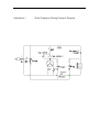
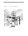
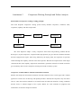
S/N : DLC100R001
DLC-100R
WATER DISPENSER
SERVICE MANUAL
Prepared By Water Dispenser Development Dept
NOV. , 2004
DIRECTORY
1.Working Principle ..................................................................................................................1
2.Main Technical Parameters ......................................................................................................1
3. Main Components and Their Functions ................................................................................1
4. List of Universal and Wear Parts.............................................................................................2
5.Common Failures and Maintenance Methods..........................................................................2
6. Cautions ................................................................................................................................3
7. Attachment 1
Wiring Principle Diagram.............................................................................4
8. Attachment2
Exploded View ..........................................................................................5
9. Attachment 3
Compressor Working Principle and Failure Analysis……………………...6
I. Working principle
The water dispenser is a kind of device, which provides bottled drinking water (distilled water,
pure water, mineral water, etc.) or daily life water treated through purification equipment to people for
drinking, after being heated, cooled or at its original water temperature.
Diversion and shunt functions: through the effect of atmospheric pressure, guide 3 gallons or 5
gallons of commercial water contained in a large bottle, through the bottle supporter, into their tanks
respectively, to realize the purpose of auto provision and supplementation of water.
Heating function: guide the water into a stainless tank of about 1.5L, heat the water and
automatically maintain it at above 90•, by means of a built-in 420W heating tube automatically
controlled by a 92• temperature controller, for instant use.
Cooling function: through a complete set of “compressor – condenser – evaporator” system, the
compressor cool the pure water inside the cool tank by using R134a as the cooling medium. Under the
auto control of the temperature controller, keep the temperature of water and refrigerator below 10•
for instant use.
II. Main Technical Parameters
Power Supply
115V~/60Hz
Surrounding
Temperature
10•-38•
Relative humidity
•45•-75•
Height above sea level
Less than 1000m
Heating power
420W
Ability to prepare hot
water
5L/h
Cooling power
100W
Ability to prepare cold
water
1L/h
Service conditions
In the ambient air, there is no flammable, explosive and corrosive gas and
conducting dust, and no strenuous shock.
III. Main Components and Their Functions
Here we introduce the water dispenser’s major components and their functions. for the drawings, see
Attachment 2.
Bottle supporter(2): a bottle head is connected to support the drinking water bottle.
Cold tank assembly(6): the cold tank is used for preparing and storing cold water and also for shunt; a
temperature sensor is fixed in the cold tank to determine water temperature.
Hot tank assembly(35): the hot tank contains a heating wire, one end of which connects a dry-boiling
prevention temperature controller to avoid dry boiling; a temperature sensor
is fixed in the cold tank to determine water temperature.
Compressor assembly(36): including PTC starter, condenser, etc., containing R134a cool-producing
medium.
Tap assembly(46,47): outlet of the water dispenser, made of edible grade plastic.
Defrosting pan(37): receiving water overflowing out of the water glass.
Separator(4); separate the water from the drinking water bottle.
Refrigerator chest(28); supply refrigeratory function.
Decorative panel of the door(30): replaceable and easy-cleaning.
Decorative panel of front carapace(49); replaceable and easy-cleaning.
IV. List of Universal and Wear Parts
See the exploded view in Attachment 2.
Power switch(5)• 115V~/10A
Hot tank assembly(35)•
plastic•tumbler switch.
115V~/60Hz/420W•insulation cotton, temperature sensor and self-reset
temperature controller are installed in advance.
Bottle supporter(2)
Tap assembly(46,47)•inner the water dispenser.
Connecting tube(14)•silica gel.
Block of protect key-press(44)•protect the children.
V. Common Failures and Maintenance Methods
No.
1
Problems
Possible reasons
The whole unit fails to
Elimination
Power is not supplied
Inspect power lead and socket.
1.
1.
work
2
No water comes out
after
the
bottle
is
The cold tank or hot tank does
not discharge air smoothly;
Shake the water dispenser gently;
mounted.
2.
The tap is broken or tap silica gel
2.
Replace the tap.
1.
wait for 5 • 10 minute • the
falls off.
3
Hot water is not hot
1.
96• bimetallic thermostat acts•
2.
Heating wire has poor contact or
is damaged.
4
Cold water is not cold
Cooling system is damaged or aging.
thermostat will self-reset•
2.
Inspect or replace the hot tank.
Inspect the system or replace its
components. See Attachment 3.
5
Water leakage at the
The tap is broken
Replace the tap.
tap.
6
Water leakage inside
1.
the machine.
The sealing ring of cold tank
becomes loose
2.
The inside pipeline becomes
loose or damaged
1• Open the upper cover and fix
the sealing ring
2• Inspect or replace the inside
silica gel tube.
VI. Cautions
1. Wait for 5-10 minute after the 96• bimetallic thermostat acts. It will self-reset. If multiple false
prevention actions happen to the same machine, confirm whether the 96• bimetallic thermostat
causes greater errors. It is required to replace the manual reset temperature controller.
2. In case water leakage, failure to reset or component rupture happen to the tap, replace the entire
tap, without repairing it.
3. In maintenance or cleaning, be sure not to pull the sealing ring off the cold tank. If it gets loose,
repair it in due course.
Attachment 1
Water Dispenser Wiring Principle Diagram
Attachment 2
Water Dispenser Exploded View
Attachment 3
Compressor Working Principle and Failure Analysis
Brief outline of compressor cooling working principle
The water dispenser compressor cooling system mainly includes compressor, condenser, filter,
evaporator, capillary and other components.
Drying filter
Capillary
Condenser
Evaporator
Compressor
The water dispenser adopts a rotary compressor filled with cool-producing medium R134a.
R134a gas is, by the compressor, compressed into high-pressure gas, goes into the condenser and then
becomes high-pressure liquid. After being filtered by the drying filter, the liquid has its pressure
reduced through the capillary, and then enters the evaporator. Because the evaporator has much larger
volume than that of the capillary, liquid freon will absorb a great deal of heat from outside to become
gas, and finally returns to the compressor, forming the closed circulatory system.
Compressor common failures and their maintenance methods
Because the compressor and electrical machine are both sealed, there are a suction pipe and a exhaust
pipe but no cut-off valve on the body, and capillary throttle is utilized, the compressor may also fail to
work or cause the electrical machine to be burned when the electrical machine’s cooling conditions
become worse or failures happen in the system. Below are some methods for judgment and
maintenance of common compressor failures.
I. Methods for Compressor Maintenance
1.
The single hermetic compressor has three terminals on the body:
R•primary coil or moving coil
S•starting coil
C•public point
2.
Judgment of compressor exhaust pipe oil vent
Generally, little oil discharges from a hermetic compressor. If oil is found to drip from the exhaust
pipe continuously, it is shown that the compressor is discharging too much oil. Over oil discharge
is mainly because that the clearance between cylinder and piston exceeds more than 1.5 times the
stipulated maximum fit clearance. In this case, disassemble the compressor, and inspect the fit
clearance between cylinder and piston. If it is out-of-tolerance, utilize a new piston.
II. Judgment of Compressor Electrical Machine Burning
1.
Winding turnoff
detect the three- winding by using an ohmmeter or a multimeter. If the
resistance between any two windings is infinite, turnoff happens.
2.
Winding earthing
with a multimeter (at low resistance level), measure between the three
terminals from the hermetic compressor and the copper pipes out of the body respectively. If the
resistance between any one of the terminals and the ground is zero, the winding is short-circuited.
3.
Winding short
with an ohmmeter or a multimeter, measure the insulation resistance between
any two windings. If the insulation resistance is too low, the windings are short-circuited.
III. Compressor Shaft Seizing and Cylinder Blocking
Compressor shaft seizing and cylinder blocking mean that broken-in surfaces of moving parts hug
each other and can no longer run, which are caused by bad lubricating parts, oil cut-off or blocked oil
circuits.
Troubleshooting: disassemble the compressor to determine where the failure takes place. In the
case of shaft seizing, knock on the seized surface or counterbalance with a wood stick or a copper rod.
If it moves slightly, that would be good, and otherwise replace the compressor.


![CK138 Single-door controller user manual [Ver 2.5]](http://vs1.manualzilla.com/store/data/005724760_1-b2fe61d7068f1fe75d1e9cbf42d7289e-150x150.png)