1
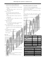
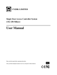
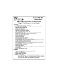
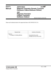
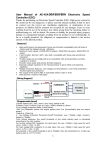
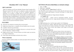
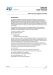
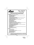
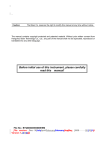
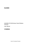
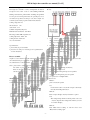
CK138 Single-door controller user manual [Ver 2.5]
Product Description:
If you have normal DC 12V Power supply only, please connect it
This single-door controller is a series of independent ones that are
this way:
developed for the control of exits of office building, intellectual
building, residential area, public channel of building, through which
user can open door with respondent card, can open with pass code or
can with both respondent card and pass code, then a simple door
controller system solution program is made. Product character:
working voltage: DC 12V
≤1.5A
≤1A
unlock current:
static current:
available card quantity: 800 pieces
Maximum card-read distance: 15cm-20cm
RF card type: EM or EM compatible card
℃~70℃
working moisture: 10%~90%
working temperature: -40
1.
1st pin connects power anode+12V and 2nd pin connects
cathode, attention: Anode and cathode must not be wrongly
size: 117×117×21mm
connected, or controller is burnt.
2.
Special attention:
5th and 6th pins connect switch, and 7th and 8th pins contact
door bell without different between anode and cathode.
1. please strictly do per user manual.
3.
2. please don’t do with power on! Need pay more special attention
to keep door controller work steadily, please don’t connect
electric lock directly with controller.
on anode and cathode.
How to assemble:
programming setup way:
Unpack cross-screw that fixes faceplate and motherboard, then take
original management pass word is 12345 and user password is 8888.
off motherboard and get it assembled on side wall which is at the
1.enter programming
exit, with attention on vertical orientation.
push*=>input management pass word=>push#
alert: 1. please ensure to switch off power before connecting lines
and switch on power after all lines being connected well!
2 function setup(under programming circumstance)
Please be sure that power voltage is 12v and that anode&
(1) modify management password:
cathode are in place!
push 0=>input new management password =>push#=>
again input new management password =>push#
note: password is 1-10 digital number.
circuit diagram:
(2) add user card
If you have a specific power supply with timer control, please
Method 1:
connect it as below diagram:
push 1 =>read card =>push#
note:.
if need add more than 1 card, needn’t re-input 1 and directly
read card, then finally push # button .
Method 2:
Push 1 => Input 10 digits card / keyfob number => push #
Note:
This 10 digits unique number should be printed on the card
or keyfob. (Input the first 10 digits if the number you found
is more than 10 digits)
Method 3:
Read “Master Card for adding” => read new card => read
“Master Card for adding” again
-1-
CK138 Single-door controller user manual [Ver 2.5]
(3) 4 ways to delete user card
Note: in general, please don’t change the jumper wire setup.
A. Delete all user card: push2=>push0000=>push #
B. Delete the card read: push2=>read card=>push#
Factory Reset procedure for door controller:
C. Delete lost card: push2=>10 digits card / keyfob number
1. switch off power and keep pushing RESET(holding it)
=>push#
2. switch on the power and press RESET for 3 seconds, then unhold
D. Read “Master Card for erasing” => read card => read
it and reset procedure is completed.
“Master card for erasing”
Status: the door controller goes into working status with 1 sound of
(4) setup for open mode
buzzer.
A. Open with reading valid card: push 300=>push#
Note:
B..Open with reading valid card and password: push 301=>
1. This procedure only change system password to default
push#
programming password, 12345, and user password 8888, others
C. open with reading valid card or entrying correct password:
remain the same.
push302=>push#
2. normally please don’t use initialization back to default unless user
note: original setup is 302 for reading valid card or input
forgets password.
password to open door.
Setting “Master cards”:
(5) setup for open door time
push4=>X X=>push#
1. switch off power and keep pushing RESET(holding it)
note: XX is during 00-99, measure unit is second and origin is 3
2. switch on the power and remain holding the RESET button.
seconds, and 0 is added for less than 2 digitals.
3. Read 2 cards
(6) how to modify use password
4. Unhold the Reset button. You will hear a “beep” sound.
push 5=>input 1 new password with 1-10 digit number=>push#
Note:
=>again input 1 new password with 1-10 digit number=>push#
The first card would be “Master card for adding”, while the second
to save
card is “Master card for erasing”.
Packing list:
(7) Save setup and exit from programming
push button * to save
access controller
1 set
note: above any setup after completing must be saved within 1
User manual
1 piece
minute by pushing *
Plastic insert for fixed and screw 1 bag
how to use:
Attachment 1: description for signal light
issue type
open by card: under normal working environment, door can be
Normal working circumstance
opened with 1 valid card.
red light
green light
glitter once per second
read valid card/correct password,
open by card and password: door can be opened if correct password
unlock
is input 10 seconds after card is read.
open door and push button, then
light
light
unlock
open by password: door can be opened by inputting user password.
wrong password
Light
Attention: the door controller supports 3 modes, opening by card, by
invalid card
Light
password and by card and password.
entry valid button
Light
alert to prevent from unpacking
Glitter
description for setup of jumper wire:
1. J1 jumper wire:
programming status
Light
glitter quickly
entry correct programming code
Light
light
entry wrong programming code
Light
Attachment2:description for buzzer sound
2nd and 3rd pins of J1 are connected and PUSH exports the signal
issue type
of keeping open, with N.O as default.
normal working status
1st and 2nd pins of J1 are connected and PUSH exports the signal
read valid card/correct password, then unlock.
of keeping close.
2.J2 jumper wire
2nd and 3rd pins of J2 are connected and PUSH exports GND low
voltage signal, with GND as default.
1st and 2nd pins of J2 are connected, PUSH exports 12V high
voltage signal.
-2-
buzzer
2 short- toot
open door and push button, then unlock
1 short-toot
wrong password
1 short toot, then 1 long toot
invalid card
1short toot, then 1 long toot
entry valid button
sort toot
programming status
2 short toots
entry correct programming code
2 short toots
entry wrong programming code
3 short toots