1
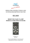
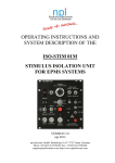
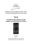
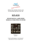
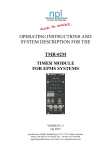
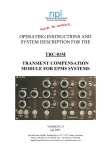
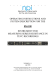
OPERATING INSTRUCTIONS AND SYSTEM DESCRIPTION FOR THE PEN-03M PENETRATION MODULE FOR EPMS SYSTEMS VERSION 1.3 npi 2014 npi electronic GmbH, Bauhofring 16, D-71732 Tamm, Germany Phone +49 (0)7141-9730230; Fax: +49 (0)7141-9730240 [email protected]; http://www.npielectronic.com PEN-03M User Manual ___________________________________________________________________________ Table of Contents 1. Safety Regulations ............................................................................................................ 3 2. EPMS-07 Modular Plug-In System .................................................................................. 4 2.1. General System Description / Operation ..................................................................... 4 2.2. EPMS-07 Housing ....................................................................................................... 4 2.3. EPMS-E-07 Housing ................................................................................................... 4 2.4. PWR-03D .................................................................................................................... 4 2.5. System Grounding ....................................................................................................... 5 EPMS-07 ..................................................................................................................... 5 EPMS-E-07.................................................................................................................. 5 2.6. Technical Data ............................................................................................................. 5 EPMS-07 ..................................................................................................................... 5 EPMS-E-07.................................................................................................................. 5 3. PEN-03M Penetration Module ......................................................................................... 6 3.1. PEN-03M Components................................................................................................ 6 3.2. System Description ...................................................................................................... 6 3.3. Description of the Front Panel and Operation ............................................................. 6 4. Connecting and Testing the PEN-03M ............................................................................ 9 5. Technical Data .................................................................................................................. 9 ___________________________________________________________________________ version 1.3 page 2 PEN-03M User Manual ___________________________________________________________________________ 1. Safety Regulations VERY IMPORTANT: Instruments and components supplied by npi electronic are NOT intended for clinical use or medical purposes (e.g. for diagnosis or treatment of humans), or for any other life-supporting system. npi electronic disclaims any warranties for such purpose. Equipment supplied by npi electronic must be operated only by selected, trained and adequately instructed personnel. For details please consult the GENERAL TERMS OF DELIVERY AND CONDITIONS OF BUSINESS of npi electronic, D-71732 Tamm, Germany. 1) GENERAL: This system is designed for use in scientific laboratories and must be operated only by trained staff. General safety regulations for operating electrical devices should be followed. 2) AC MAINS CONNECTION: While working with the npi systems, always adhere to the appropriate safety measures for handling electronic devices. Before using any device please read manuals and instructions carefully. The device is to be operated only at 115/230 Volt 60/50 Hz AC. Please check for appropriate line voltage before connecting any system to mains. Always use a three-wire line cord and a mains power-plug with a protection contact connected to ground (protective earth). Before opening the cabinet, unplug the instrument. Unplug the instrument when replacing the fuse or changing line voltage. Replace fuse only with an appropriate specified type. 3) STATIC ELECTRICITY: Electronic equipment is sensitive to static discharges. Some devices such as sensor inputs are equipped with very sensitive FET amplifiers, which can be damaged by electrostatic charge and must therefore be handled with care. Electrostatic discharge can be avoided by touching a grounded metal surface when changing or adjusting sensors. Always turn power off when adding or removing modules, connecting or disconnecting sensors, headstages or other components from the instrument or 19” cabinet. 4) TEMPERATURE DRIFT / WARM-UP TIME: All analog electronic systems are sensitive to temperature changes. Therefore, all electronic instruments containing analog circuits should be used only in a warmed-up condition (i.e. after internal temperature has reached steady-state values). In most cases a warm-up period of 20-30 minutes is sufficient. 5) HANDLING: Please protect the device from moisture, heat, radiation and corrosive chemicals. ___________________________________________________________________________ version 1.3 page 3 PEN-03M User Manual ___________________________________________________________________________ 2. EPMS-07 Modular Plug-In System 2.1. General System Description / Operation The npi EPMS-07 is a modular system for processing of bioelectrical signals in electrophysiology. The system is housed in a 19” rackmount cabinet (3U) has room for up to 7 plug-in units. The plug-in units are connected to power by a bus at the rear panel. The plug-in units must be kept in position by four screws (M 2,5 x 10). The screws are important not only for mechanical stability but also for proper electrical connection to the system housing. Free area must be protected with covers. 2.2. EPMS-07 Housing The following items are shipped with the EPMS-07 housing: EPMS-07 cabinet with built-in power supply Mains cord Fuse 2 A / 1 A, slow Front covers In order to avoid induction of electromagnetic noise the power supply unit, the power switch and the fuse are located at the rear of the housing. 2.3. EPMS-E-07 Housing The following items are shipped with the EPMS-E-07 housing: EPMS-E-07 cabinet External Power supply PWR-03D Power cord (PWR-03D to EPMS-E-07) Mains chord Fuse 1.6 A / 0.8 A, slow Front covers The EPMS-E-07 housing is designed for low-noise operation, especially for extracellular and multi channel amplifiers with plugged in filters. It operates with an external power supply to minimize distortions of the signals caused by the power supply. 2.4. PWR-03D The external power supply PWR-03D is capable of driving up to 3 EPMS-E housings. Each housing is connected by a 6-pole cable from the one of the three connectors on the front panel of the PWR-03D to the rear panel of the respective EPMS-E housing. (see Figure 1, Figure 3). A POWER LED indicates that the PWR-03D is powered on (see Figure 1). Power switch, voltage selector and fuse are located at the rear panel (see Figure 2). Note: The chassis of the PWR-03D is connected to protective earth, and it provides protective earth to the EPMS-E housing if connected. ___________________________________________________________________________ version 1.3 page 4 PEN-03M User Manual ___________________________________________________________________________ Figure 1: PWR-03D front panel view Figure 2: PWR-03D rear panel view Note: This power supply is intended to be used with npi EPMS-E systems only. 2.5. System Grounding EPMS-07 The 19" cabinet is grounded by the power cable through the ground pin of the mains connector (= protective earth). In order to avoid ground loops the internal ground is isolated from the protective earth. The internal ground is used on the BNC connectors or GROUND plugs of the modules that are inserted into the EPMS-07 housing. The internal ground and mains ground (= protective earth) can be connected by a wire using the ground plugs on the rear panel of the instrument. It is not possible to predict whether measurements will be less or more noisy with the internal ground and mains ground connected. We recommend that you try both arrangements to determine the best configuration. EPMS-E-07 The 19" cabinet is connected to the CHASSIS connector at the rear panel. The CHASSIS is linked to protective earth as soon as the PWR-03D is connected. It can be connected also to the SYSTEM GROUND (SIGNAL GROUND) on the rear panel of the instrument (see Figure 3). Important:: Always adhere to the appropriate safety measures. Figure 3: Rear panel connectors of the EPMS-E-07 2.6. Technical Data 19” rackmount cabinet, for up to 7 plug-in units Dimensions: 3U high (1U=1 3/4” = 44.45 mm), 254 mm deep EPMS-07 Power supply: 115/230 V AC, 60/50 Hz, fuse 2 A / 1 A slow, 45-60 W EPMS-E-07 External power supply (for EPMS-E): 115/230 V AC, 60/50 Hz, fuse 1.6/0.8 A, slow Dimensions of external power supply: (W x D x H) 225 mm x 210 mm x 85 mm ___________________________________________________________________________ version 1.3 page 5 PEN-03M User Manual ___________________________________________________________________________ 3. PEN-03M Penetration Module 3.1. PEN-03M Components The following items are shipped with the PEN-03M system: Penetration module for the EPMS-07 system User manual 3.2. System Description The PEN-03M module is designed to facilitate cell penetration by application of current pulses to the electrode or by overcompensating the capacity compensation (BUZZ) of the electrode. The current pulses are variable in duration, amplitude and frequency while in BUZZ mode only duration can be set. Typically, the PEN-03M is used with SEC-03M single electrode clamp amplifier(s) and/or the HVC-03M high voltage clamp module. 3.3. Description of the Front Panel and Operation Figure 4: PEN-03M front panel view ___________________________________________________________________________ version 1.3 page 6 PEN-03M User Manual ___________________________________________________________________________ In the following description of the front panel elements each element has a number that is related to that in Figure 4. The number is followed by the name (in uppercase letters) written on the front panel and the type of the element (in lowercase letters). Then, a short description of the element is given. (1) + / - switch Switch for setting the polarity of the DC current or current pulse, dependent on the mode of operation (see also #3). (2) AMPLITUDE potentiometer Potentiometer for setting the amplitude of the DC current or current pulse, dependent on the mode of operation (see also #3). (3) DC / PULSE / BUZZ switch Switch for setting the mode of operation. DC: a DC current is applied to the electrode. The duration is set by the DURATION potentiometer (#9) and the amplitude by the AMPLITUDE potentiometer (#2). The FREQUENCY potentiometer (#10) is disabled in this mode. PULSE: current pulses are applied to the electrode. The duration is set by the DURATION potentiometer (#9), the frequency by the FREQUENCY potentiometer (#10) and the amplitude by the AMPLITUDE potentiometer (#2). BUZZ: the capacity compensation of the electrode gets overcompensated resulting in tiny vibrations of the electrode tip. The duration is set by the DURATION potentiometer (#9), the AMPLITUDE potentiometer (#2) and the FREQUENCY potentiometer (#10) are disabled in this mode. (4) ACTIVATE button Button for starting operation (see also #3). (5) headstage connector Connector for the headstage of amplifier B. (6) REMOTE BNC connector BNC for connecting a remote control (optional). ___________________________________________________________________________ version 1.3 page 7 PEN-03M User Manual ___________________________________________________________________________ (7) connecting cables Cables for connecting the PEN-03 to the SEC-03M amplifier(s). A: to amplifier A; B: to amplifier B (see also #11). (8) headstage connector Connector for the headstage of amplifier A. (9) DURATION potentiometer Potentiometer for setting the duration of the DC current, current pulse or capacity compensation, dependent on the mode of operation (see also #3). (10) FREQ. potentiometer Potentiometer for setting the frequency of the current pulse train. (11) target selector Switch for selecting the electrode OFF: A: B: AUX: the PEN-03M is disabled. current pulses, DC current or BUZZ (overcompensation) is applied to the electrode connected to amplifier A (see also #7 and #8). current pulses, DC current or BUZZ is applied to the electrode connected to amplifier B (see also #5 and #7). BUZZ is applied to the electrode connected to the AUX instrument (e.g. HVC03M). Only the DURATION potentiometer (#9) is active, i.e. only the duration of the BUZZ can be set. Important: The PEN-03M is disabled only if the target selector (#11) is in OFF position. Therefore, always disable the PEN-03M if the electrode is inside the cell in order to prevent the cell from damage if the start button (#4) is pressed unintentionally. ___________________________________________________________________________ version 1.3 page 8 PEN-03M User Manual ___________________________________________________________________________ 4. Connecting and Testing the PEN-03M In the following it is assumed that the PEN-03 should be connected to an SEC-03M as amplifier A. Connect the cable of the PEN-03M module, Channel A to the headstage connector of the SEC-03M (see also #7, Figure 4) Connect the headstage of the SEC-03M to the headstage connector for amplifier A of the PEN module (see also #8, Figure 4) Set the target selector of the PEN-03M to A (see also #11, Figure 4) Connect a cell model to the headstage Connect an oscilloscope to the outputs of the SEC Power on the EPMS housing. The easiest way to test now is to set the mode of operation switch (#3, Figure 4) to BUZZ and the DURATION potentiometer in the rightmost position (maximum length). If the ACTIVATE button is now pressed one should see the overcompensation of the electrode on the oscilloscope. 5. Technical Data PEN-03M Duration range: 15 … 1000 ms Amplitude range: 0 … 120 nA into 100 M Frequency range: 10 … 1000 Hz Size: front panel 12 HP (60.6 mm) x 3U (128,5 mm), 7” (175 mm) deep EPMS-07 SYSTEM Power requirements: 115/230 V AC, 60/50 Hz, fuse 2 A / 1 A, slow, 45-60 W (dependent on the modules plugged in) Dimensions: 19” rackmount cabinet, 3U high (1U = 1 ¾” = 44.45 mm) ___________________________________________________________________________ version 1.3 page 9