1
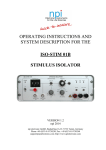
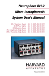
OPERATING INSTRUCTIONS AND SYSTEM DESCRIPTION FOR THE HVC-03M HIGH VOLTAGE CLAMP MODULE FOR EPMS SYSTEMS VERSION 2.5 npi 2014 npi electronic GmbH, Bauhofring 16, D-71732 Tamm, Germany Phone +49 (0)7141-9730230; Fax: +49 (0)7141-9730240 [email protected]; http://www.npielectronic.com HVC-03M User Manual ___________________________________________________________________________ Table of Contents 1. Safety Regulations ............................................................................................................ 3 2. EPMS-07 Modular Plug-In System .................................................................................. 4 2.1. General System Description / Operation ..................................................................... 4 2.2. EPMS-07 Housing ....................................................................................................... 4 2.3. EPMS-E-07 Housing ................................................................................................... 4 2.4. PWR-03D .................................................................................................................... 4 2.5. System Grounding ....................................................................................................... 5 EPMS-07 ..................................................................................................................... 5 EPMS-E-07.................................................................................................................. 5 2.6. Technical Data ............................................................................................................. 5 EPMS-07 ..................................................................................................................... 5 EPMS-E-07.................................................................................................................. 5 3. HVC-03M High Voltage Clamp Module ......................................................................... 6 3.1. HVC-03M Components ............................................................................................... 6 3.2. System Description ...................................................................................................... 6 3.3. Description of the Front Panel and Operation ............................................................. 7 4. Cell Model (optional) ....................................................................................................... 10 4.4. Introduction ................................................................................................................. 10 4.5. Cell Model Description ............................................................................................... 10 4.6. Connections and Operation ......................................................................................... 11 Checking the Configuration with the Cell Model ....................................................... 11 5. Test and Tuning Procedures ............................................................................................. 12 5.1. Current Headstage Bias Current Adjustment .............................................................. 12 5.2. Capacitance Compensation ......................................................................................... 13 6. Operation .......................................................................................................................... 15 6.1. Connections ................................................................................................................. 15 7. Technical Data .................................................................................................................. 16 ___________________________________________________________________________ version 2.5 page 2 HVC-03M User Manual ___________________________________________________________________________ 1. Safety Regulations VERY IMPORTANT: Instruments and components supplied by npi electronic are NOT intended for clinical use or medical purposes (e.g. for diagnosis or treatment of humans), or for any other life-supporting system. npi electronic disclaims any warranties for such purpose. Equipment supplied by npi electronic must be operated only by selected, trained and adequately instructed personnel. For details please consult the GENERAL TERMS OF DELIVERY AND CONDITIONS OF BUSINESS of npi electronic, D-71732 Tamm, Germany. 1) GENERAL: This system is designed for use in scientific laboratories and must be operated only by trained staff. General safety regulations for operating electrical devices should be followed. 2) AC MAINS CONNECTION: While working with the npi systems, always adhere to the appropriate safety measures for handling electronic devices. Before using any device please read manuals and instructions carefully. The device is to be operated only at 115/230 Volt 60/50 Hz AC. Please check for appropriate line voltage before connecting any system to mains. Always use a three-wire line cord and a mains power-plug with a protection contact connected to ground (protective earth). Before opening the cabinet, unplug the instrument. Unplug the instrument when replacing the fuse or changing line voltage. Replace fuse only with an appropriate specified type. 3) STATIC ELECTRICITY: Electronic equipment is sensitive to static discharges. Some devices such as sensor inputs are equipped with very sensitive FET amplifiers, which can be damaged by electrostatic charge and must therefore be handled with care. Electrostatic discharge can be avoided by touching a grounded metal surface when changing or adjusting sensors. Always turn power off when adding or removing modules, connecting or disconnecting sensors, headstages or other components from the instrument or 19” cabinet. 4) TEMPERATURE DRIFT / WARM-UP TIME: All analog electronic systems are sensitive to temperature changes. Therefore, all electronic instruments containing analog circuits should be used only in a warmed-up condition (i.e. after internal temperature has reached steady-state values). In most cases a warm-up period of 20-30 minutes is sufficient. 5) HANDLING: Please protect the device from moisture, heat, radiation and corrosive chemicals. ___________________________________________________________________________ version 2.5 page 3 HVC-03M User Manual ___________________________________________________________________________ 2. EPMS-07 Modular Plug-In System 2.1. General System Description / Operation The npi EPMS-07 is a modular system for processing of bioelectrical signals in electrophysiology. The system is housed in a 19” rackmount cabinet (3U) has room for up to 7 plug-in units. The plug-in units are connected to power by a bus at the rear panel. The plug-in units must be kept in position by four screws (M 2,5 x 10). The screws are important not only for mechanical stability but also for proper electrical connection to the system housing. Free area must be protected with covers. 2.2. EPMS-07 Housing The following items are shipped with the EPMS-07 housing: EPMS-07 cabinet with built-in power supply Mains cord Fuse 2 A / 1 A, slow Front covers In order to avoid induction of electromagnetic noise the power supply unit, the power switch and the fuse are located at the rear of the housing. 2.3. EPMS-E-07 Housing The following items are shipped with the EPMS-E-07 housing: EPMS-E-07 cabinet External Power supply PWR-03D Power cord (PWR-03D to EPMS-E-07) Mains chord Fuse 1.6 A / 0.8 A, slow Front covers The EPMS-E-07 housing is designed for low-noise operation, especially for extracellular and multi channel amplifiers with plugged in filters. It operates with an external power supply to minimize distortions of the signals caused by the power supply. 2.4. PWR-03D The external power supply PWR-03D is capable of driving up to 3 EPMS-E housings. Each housing is connected by a 6-pole cable from the one of the three connectors on the front panel of the PWR-03D to the rear panel of the respective EPMS-E housing. (see Figure 1, Figure 3). A POWER LED indicates that the PWR-03D is powered on (see Figure 1). Power switch, voltage selector and fuse are located at the rear panel (see Figure 2). Note: The chassis of the PWR-03D is connected to protective earth, and it provides protective earth to the EPMS-E housing if connected. ___________________________________________________________________________ version 2.5 page 4 HVC-03M User Manual ___________________________________________________________________________ Figure 1: PWR-03D front panel view Figure 2: PWR-03D rear panel view Note: This power supply is intended to be used with npi EPMS-E systems only. 2.5. System Grounding EPMS-07 The 19" cabinet is grounded by the power cable through the ground pin of the mains connector (= protective earth). In order to avoid ground loops the internal ground is isolated from the protective earth. The internal ground is used on the BNC connectors or GROUND plugs of the modules that are inserted into the EPMS-07 housing. The internal ground and mains ground (= protective earth) can be connected by a wire using the ground plugs on the rear panel of the instrument. It is not possible to predict whether measurements will be less or more noisy with the internal ground and mains ground connected. We recommend that you try both arrangements to determine the best configuration. EPMS-E-07 The 19" cabinet is connected to the PROTECTIVE EARTH connector at the rear panel. The chassis is linked to protective earth only if the PWR-03D is connected. It can be connected also to the SYSTEM GROUND (SIGNAL GROUND) on the rear panel of the instrument (see Figure 3). Important:: Always adhere to the appropriate safety measures. Figure 3: Rear panel connectors of the EPMS-E-07 2.6. Technical Data 19” rackmount cabinet, for up to 7 plug-in units Dimensions: 3U high (1U=1 3/4” = 44.45 mm), 254 mm deep EPMS-07 Power supply: 115/230 V AC, 60/50 Hz, fuse 2 A / 1 A slow, 45-60 W EPMS-E-07 External power supply (for EPMS-E): 115/230 V AC, 60/50 Hz, fuse 1.6/0.8 A, slow Dimensions of External power supply: (W x D x H) 225 mm x 210 mm x 85 mm ___________________________________________________________________________ version 2.5 page 5 HVC-03M User Manual ___________________________________________________________________________ 3. HVC-03M High Voltage Clamp Module 3.1. HVC-03M Components The following items are shipped with the HVC-03M system: High voltage clamp module for the EPMS-07 system User manual Headstage 3.2. System Description The HVC-03M high voltage clamp module is designed for current injection into cells. It extends one or two SEC-03M modules so that two electrode voltage clamp experiments using high voltages can be performed. It features OFFSET cancellation, capacity compensation of the electrode capacity, series resistance compensation, an electrode resistance measurement unit and correction for BIAS current. Important: A EPMS-07-H housing with a high voltage power supply is required for the HVC-03M as indicated at the rear panel of the EPMS-07-H housing. The HVC-03M can also be operated as a module for iontophoresis using an external control signal (see below). ___________________________________________________________________________ version 2.5 page 6 HVC-03M User Manual ___________________________________________________________________________ 3.3. Description of the Front Panel and Operation Figure 4: HVC-03M front panel view In the following description of the front panel elements each element has a number that is related to that in Figure 4. The number is followed by the name (in uppercase letters) written on the front panel and the type of the element (in lowercase letters). Then, a short description of the element is given. (1) DUAL LED LED indicating the status of the HVC-03M. Lights, if the connected SEC-03M is active. The DUAL LED of the respective SEC-03M amplifier lights as well. The LED lights also, if the control selector switch #5 is in EXT position, e.g. for iontophoresis. (2) Potential / resistance display Display showing the potential at the electrode tip in mV, the electrode resistance in M or the current flowing in nA. The value shown here is also provided at OUT connector #9. ___________________________________________________________________________ version 2.5 page 7 HVC-03M User Manual ___________________________________________________________________________ (3) BIAS trim pot Trim pot for adjusting the BIAS current. (4) CAP.COMP. potentiometer Potentiometer for setting the capacity compensation of the electrode. (5) Control selector switch Switch for selecting the instrument that controls the HVC-03M. A: OFF: B: EXT: the amplifier is controlled by SEC-03M labeled A. the amplifier is disconnected from all external signals and does not generate current. The LED at the headstage does not light in OFF position. the amplifier is controlled by SEC-03M labeled B. the amplifier is controlled by an external signal, e.g. for being used for iontophoresis. Note: If the control selector switch is in A or B position, the respective SEC-03M amplifier cannot be operated as a single electrode amplifier in BRIDGE mode. Only two electrode voltage or current clamp mode is possible. (6) OFFSET potentiometer Potentiometer for OFFSET cancellation of the electrode. (7) EXT IN. BNC connector Input BNC connector for an external signal. By application of an external signal to this BNC connector and setting the control selector switch (#5) to EXT, the HVC03M can be used as amplifier for iontophoresis. Scaling: 100 nA / 1 V. (8) HEADSTAGE connector Connector for the HVC-03M headstage. ___________________________________________________________________________ version 2.5 page 8 HVC-03M User Manual ___________________________________________________________________________ (9) OUT BNC connector BNC connector providing the current signal of the high-voltage headstage. Scaling: 100 nA / 1 V or mV respectively. (10) RS COMP. potentiometer (optional) Optional, only needed for very large currents(> 2 µA) (11) RCEL, ICEL, VCEL switch Switch for showing the electrode resistance in M (RCEL), for showing the electrode current in nA (ICEL) or for showing the electrode potential in mV (VCEL) at display #2. ___________________________________________________________________________ version 2.5 page 9 HVC-03M User Manual ___________________________________________________________________________ 4. Cell Model (optional) 4.4. Introduction The cell model is designed to be used to check the function of the instrument either 1. just after unpacking to see whether the instrument has been damaged during transport or 2. to train personnel in using the instrument or 3. in case of trouble to check which part of the setup does not work correctly, e.g. to find out whether the amplifier is broken or if something is wrong with the electrodes or holders etc. This cell model consist only of passive elements, i.e. resistors that simulate the resistance of the cell membrane and the electrodes and a capacitance that simulates the capacitance of the cell membrane (see Figure 5). A switch allows to simulate two different cell conditions: one with 10 M membrane resistance and a second with 1 M membrane resistance. The membrane capacitance is always 5 nF. Note: This cell model is not suitable for SEC-03M amplifiers in single electrode operation. 4.5. Cell Model Description Figure 5: HVC passive cell model ___________________________________________________________________________ version 2.5 page 10 HVC-03M User Manual ___________________________________________________________________________ HV 45V BNC: connector for the headstage of the HVC-03M (current), resistance: 33 M GND/ON switch: switch to ground the current headstage for BIAS current adjustment (see below) CELL membrane switch: switch for cell membrane representing a membrane of either 10 M or 1 M resistance SEC SUBD: connector for the SEC (potential) headstage, resistance: 33 M 4.6. Connections and Operation Checking the Configuration with the Cell Model Turn POWER switch of the EPMS-07 housing off. Connect the BNC jack HV 45V of the cell model to the BNC connector of the HVC-03M headstage. Connect the SEC-03M headstage to the SMB connector SEC at the cell model. Switch the CELL membrane switch (see Figure 5) to the desired position. Turn all controls at the amplifier to low values (less than 1) and the OFFSET in the range of 5. Turn POWER switch of the EPMS-07 housing on. Now you can adjust the amplifier and apply test pulses to the cell model. Connection to the BNC jack and the SMB connector gives access to the cell via electrodes each with 33 M resistance. The upper position the CELL membrane switch simulates cell with a resistance of 1 M. The lower position represents a cell membrane with 10 M. ___________________________________________________________________________ version 2.5 page 11 HVC-03M User Manual ___________________________________________________________________________ 5. Test and Tuning Procedures 5.1. Current Headstage Bias Current Adjustment Caution: It is important that this tuning procedure is performed ONLY after a warm-up period of at least 30 minutes! The tuning procedure must be performed regularly (at least once a month) with great care since the bias current changes over time and it determines the accuracy of the system. The HVC-03M is equipped with a high-voltage current source that is connected to the current injecting electrode and performs the current injection. This current source has a highimpedance floating output. Therefore the zero point (the zero of the bias current) of the current source must be defined, i.e. without an input signal there should not be an output current. Since the high-voltage FET amplifiers that are used become warm from the internal heat dissipation and their characteristics are strongly temperature dependent, the calibration procedure has to be done periodically by the user. The tuning procedure is done using the BIAS control and one resistance of a few and one of a few M. It is based on Ohm's Law (U = R * I). If the headstage generates an output current, this current will cause a voltage deflection at a test resistor. This voltage deflection is proportional to the output current and is displayed on the digital meter. Using the BIAS control the monitored voltage can be set to 0. The tuning procedure is performed using high-value resistors or the cell model. It cannot be performed with an electrode, since there are always unknown potentials involved (tip potential, junction potentials etc.). Warning: High voltage! Always turn power off when working directly on the current headstage output (see Chapter 1). Switch the control selector switch (#3) to off. This ensures that no external signal affects the HVC-03M. Connect the ELECTRODE connector of the HVC-03M headstage to ground. Set switch #11 to VCEL. Set the reading of the display (#2) to 0 using the OFFSET potentiometer (#11). After tuning the electrode potential OFFSET to zero, simulate an electrode by grounding the headstage via 10 M resistor. The digital display (and the OUT connector (#9)) now shows a voltage deflection that is related to the BIAS current of the headstage according to Ohm's Law. Cancel this voltage by tuning the headstage BIAS trim pot (#3). The current is 0 if the voltage deflection is 0. ___________________________________________________________________________ version 2.5 page 12 HVC-03M User Manual ___________________________________________________________________________ 5.2. Capacitance Compensation High resistances of electrodes and stray capacitances form a low-pass filter which deteriorates the shape of intracellular stimuli. The frequency response of the amplifier is improved considerably by using the capacitance compensation function. This function is based on positive feedback (“negative capacitance”) circuit. The tuning of the capacitance compensation control can be performed using pulses provided by the electrode resistance test circuit or external pulses. With the electrode in the bath the CAP.COMP. control is turned clockwise until there is no capacitive artifact on the potential output (see Figure 6). Immerse the electrode into the bath as deep as necessary during the experiment. Set switch #11 to VCEL and tune the OFFSET to zero. Push the RCEL switch (#11, Figure 4) or apply square pulses to the EXT IN BNC (#7, Figure 4), switch the control selector switch (#5, Figure 4) to EXT, and watch the potential output. Compensate the input capacitance as shown in Figure 6 using the CAP.COMP potentiometer (#4, Figure 4). Figure 6 illustrates the capacitance compensation procedure using a 100 M resistor that represents the electrode. The upper diagram shows an undercompensated capacitance. In the diagram in the middle the capacitance is slightly overcompensated and in the lower diagram it is well compensated. ___________________________________________________________________________ version 2.5 page 13 HVC-03M User Manual ___________________________________________________________________________ Figure 6: Tuning of the capacitance compensation using a 100 M resistor ___________________________________________________________________________ version 2.5 page 14 HVC-03M User Manual ___________________________________________________________________________ 6. Operation 6.1. Connections The HVC-03M can be used together with an SEC-03M as current module for two electrode voltage/current clamp. In two electrode voltage clamp mode, the SEC-03M does not work as switched amplifier, but as continuous mode amplifier for potential registration. Connections to the SEC-03M are not required. All signals are wired via the EPMS bus. For operation as a high voltage clamp module for two electrode voltage/current clamp simply connect the headstage to the headstage connector (#9, Figure 4) and the current output (#6, Figure 4) to an oscilloscope or data acquisition system, respectively. For potential registration the POTENTIAL OUTPUT x10 mV BNC connector of the SEC-03M is used. In two electrode voltage/current clamp mode, the CURRENT OUTPUT 10 nA/V BNC connector of the SEC-03M is disabled, and the current output of the HVC-03M is used. Important: Since the HVC-03M has a ten times higher current amplification, the CURRENT STIMULUS INPUT of the SEC-03M is now 10 nA / V and the holding current range is up to 100 nA. The current display at the SEC-03M is not valid. The HVC-03M can also be used as amplifier for iontophoresis. For operation as a iontophoretic amplifier connect a stimulus generator or a data acquisition system, respectively, to the EXT IN BNC connector (#8, Figure 4) und set the control selector switch (#3, Figure 4) to EXT The HVC-03M generates a current proportional to the voltage at EXT IN BNC (scaling: 100 nA / 1 V). Note: All signal outputs are coarse and unfiltered directly from the headstages. Thus, we recommend to use always additional filters for signal conditioning. ___________________________________________________________________________ version 2.5 page 15 HVC-03M User Manual ___________________________________________________________________________ 7. Technical Data HVC-03M CURRENT RANGE: max. 1µA in 100 M CURRENT OUT: 100 nA / V POTENTIAL OUT: mV OFFSET compensation range: 200 mV EXT IN: 100 nA / 1 V Size: front panel 12 HP (60.6 mm) x 3U (128,5 mm), 7” (175 mm) deep EPMS-07 SYSTEM Power requirements: 115/230 V AC, 60/50 Hz, fuse 2 A / 1 A, slow, 45-60 W (dependent on the modules plugged in) Dimensions: 19” rackmount cabinet, 3U high (1U = 1 ¾” = 44.45 mm) ___________________________________________________________________________ version 2.5 page 16