1
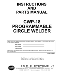
SAFETY INSTRUCTIONS AND
OPERATORS MANUAL
FOR BEVELING MACHINE
PBM-2000
Please record your equipment identification information below for future reference. This information can be found
on your machine nameplate.
Model Number
Serial Number
Date of Purchase
Whenever you request replacement parts or information on this equipment, always supply the information you
have recorded above.
A DIVISION OF WELD TOOLING CORPORATION
3001 WEST CARSON STREET
PITTSBURGH, PENNSYLVANIA
USA 15204-1899
PHONE: 1- 800-245-3186 http://www.bugo.com TELEFAX: 1- 412- 331- 0383
LIT-PBM-IPM-O404
- 2 iiiiiiiiiiiThe bevelling machine is designed for milling steel edges
prior to welding. It is reliable and simple to use. The machine can be
used for bevelling straight and curved steel sheets and pipes. It allows you to
bevel steel edges between 30 and 60 degrees. maximal width of cut is 18 mm.
When equipped with special attachment it can also work on pipes above 150
mm diameter.
iiiiiiiiBefore you start work with the machine, please read these
instructions carefully. Take special note of safety recommendations.
Power supply: 110 V AC 50÷60 Hz
Motor: electric, single phase, induction, with work capacitor.
Power: 1,1 kW
Speed: 2820 min -1
Maximal instantaneous overload: (18 A)
Cut of point: (22 A)
Electric safeguard: neutral earthing
Tool: double milling head with multi-blade inserts
Cutting speed: around 550 m/min
Max. width of cut: b=18mm for 45° angle (see drawing 1)
Range of angles: 30°< β < 60° (drawing 1)
Total weight: around 19,5 kg
Fuse: 2 A
β
b
- 3 -
- metal box
- bevelling machine with a set of inserts
- curves and pipes attachment (part 309÷315) - option
- tool box (part 601)
- 2 Allen wrenches:
................hex s3 (part 605)
................hex s6 (part 602)
- milling head fastening tool (part 604)
- milling head interlock (part 606)
- milling head puller (part 607)
- instructions
.......tT
The PBM-2000 comes in a ready-to-use state. The only operation that needs to
be carried out is adjusting it to workpiece thickness and the bevelling angle.
Precise instructions how to do it are given below in point 5.
.......Plug machine into mains. Both the plug and the socket must be earthed. Lift
the machine and place it vertically on its horizontal slide, on the edge of your
workpiece, which should be on your right hand side. Make sure that the tool
does not touch the workpiece. You can now turn the machine on by pressing
main switch (507) to position "I". To switch machine off press switch (507) to
position "O". You can now start the motor pressing switch (510, button "I") what
will be signalled with an amber light coming on (506). To stop the motor press
switch (510) again (button "O").
.......Start sliding the machine slowly to the right, untill such a moment that the
tool starts to cut steel but remember - the direction of feed is marked on the
spindle housing (205). The feed rate depends on the thickness of steel which is
being bevelled and on the composition of that steel. Most steels can be bevelled
with just one pass.
.......If the operator attempts to mill too fast and too thick, the overload red
indicator (504) will start flashing and if motor is loaded even harder power will be
cut off. To start the machine again move the tool away from bevelled edge, than
press button "O" switch (510), and after few seconds you can start the machine
again by pressing button "I" (switch 510)
.......Operator is permitted to use the machine at the brink of the cut-off point
with overload light coming on and off, but the temperature of the motor should
not exceed 85°C. Higher temperature can permanently demage rotor. This unit is
designed to work under full load for around 1 hour, after which it should cool
down for about 15 minutes. The motor will not cool down running free, but it will
get even warmer.
- 4 -
Special optional roller attachment (309÷315) allows you to bevel pipes and
curves.
1. To prepare the machine for work on pipes take the 307 slide off the machine
.....and replace it with the pipe attachment (309÷315).
2. Move the housing (205) to its "zero width of cut" position ie. when beveling
....angle is null.
3. Place machine on the edge of pipe, in such a way that the milling tool touches
....the workpiece (drawing 2). Then loosen bolts (309) and move rollers (311)
....symmetrically towards the pipe so that they rest on it. fasten both rollers. You
....can now adjust required bevelling angle.
Pay special attention to the following points:
- Power supply should be in accordance with all local regulations. Its capacity to
..earth electrical loads should be tested prior to work.
- Power supply cable should be protected from demage.
- Precise and tight fitting of the milling head and its inserts.
- Corect adjustment of the milling head to the workpiece and tighten bolts.
- 5 -
Always wear protective glasses!
Inspect the condition of milling inserts regularly and change
them when worn!
Stop machine, if any abnormal signs occur!
Always unplug machine from power supply during any work on
the tool, when adjusting angles or any other work on it.
All repairs should be carried out by authorised sevice only.
There are two adjustments mechanisms:
1. for adjusting the bevelling angle required,
2. for adjusting the machine to the thickness of steel which is being cut.
......Before you start any adjustments make sure that the machine is unpluged
from the mains.
......To change bevelling angle loosen two M8 bolts (302) located on both sides
of the milling head housing and interlocking vertical and horizontal slides. Then
change position of two slides setting the required angle according the pitch
marked on the side of the housing. After setting the right angle tighten all 302
bolts.
......The width of cut can be set by turning bolt 202 which will after the position of
the milling head. Do it by loosening two bolts 212 located on the side walls of the
housing and turning the bolt 202. Then tighten 212 bolts. The pitch shown on
the side of 205 housing gives only approximate parameters. Precise bevelling
width should be adjusted empirically by appropriate adjustment of the housing
.......The machine is equipped with a double milling head, containing twelve
cermetalic inserts. Recommended inserts are of the following type: ISO SEKN
1203 08 CERMET.
.......I case of average quality construction steel, life expectancy of those inserts
is around 150 running meters per each side of inserts. before you replace tips
for new ones make sure that all four sides of each insert were used. Take the
housing 205 off the machine. To do it, undo bolts 212, using Allen wrench - size
3 (supplied as standard). It is normally not necessary to take both milling heads
403 off the spindle 401. Using Allen wrench s3 (605) undo screws 407 and
remove inserts.
........When changing tips make sure that all inserts newly placed in the milling
head are installed square and that are pushed as far back (into the holder) as
possible. Before pushing new inserts into the milling head always remove all
swarf. drawing No 3 shows how inserts should overlap each other. Make sure
- 6 that the necessary gap of 0,2 mm is always made.
........If both milling heads were removedand the replaced on the main shaft
make sure that they are installed in the right direction and that tips of each
milling head are shifted relatively to each other for smoother work.
........If the width of cut is small then swap all inserts according to drawing No4,
thus extending their life even longer.
PARTS LISTS AND EXPLOSION DRAWINGS FOR PBM-2000 PLATE
BEVELLING MACHINE - 120V
105
109
110
111
113
DESCRIPTION
Electric motor
Holder (set)
Cushion washer 6,1
Hex. socket bolt M6x16
Nut M6
PART NUMBER
H01111-002-01-00
C02180-751-09-01
N18200-806-01-01
N18230-206-16-01
N18214-406-00-01
QTY.
1
1
4
4
5
202
205
208
210
211
212
Feed bolt
Spindle Housing
Stop pin
Round washer 8.4
Cushion washer 8.2
Handle
C02180-592-02-10
C02180-752-50-00
C02180-752-58-00
N18200-608-04-01
N18200-808-02-01
H00643-483-01-00
1
1
1
2
2
2
301a
301b
302
303
304
305
306
308
351
352
Hex. socket bolt M5x10
Hex. socket bolt M5x8
Hex. socket bolt M8x20
Guide slide I
Cushion washer 8.2
Round washer 8.4
Slides mounting I
Slides mounting II
Guide slide II
Roller set
N18230-205-10-11
N18230-205-08-11
N18230-208-20-11
C02180-593-03-00
N18200-808-02-01
N18200-608-04-01
C02180-753-06-00
C02180-753-08-00
C02180-753-07-01
C02180-753-07-30
10
2
4
1
4
4
1
1
1
2
401
402
403
404
405
406
407
408
409
410
411
412
Milling head arbor
Motor key 6x6x32
Milling head (Insert holders)
Milling head key 6x6x31
Distance ring
Milling insert
Insert screw M6x0,75x6
Safety washer MB-4
Bearing nut KM-4
Hex. socket bolt M-6x30
Washer
Cushion washer 6,1
C02180-594-01-00
C02180-754-02-00
PBM-2041
PBM-2042
C02180-594-05-00
PBM-2051
PBM-2052
PBM-2043
PBM-2044
N18230-206-30-02
C02180-594-11-00
N18200-806-01-00
1
1
2
1
1
12
12
1
1
1
1
1
501
503
504
505
506
507
508
509
510
511
512
513
514
515
Electronic module 110V
Seal l=520
Red light indicator
Screw M4x12
Amber light indicator
Main switch
Cover (upper)
Fuse socket (incl. 2A fuse)
Motor ON/OFF switch set
Rubber bushing LA10
Strain relief nut
Power cord
Capacitor
"O" ring
C02180-595-01-01
C02180-595-03-00
H00917-421-01-00
N18221-204-12-01
H00917-421-02-00
H01156-460-01-00
C02180-755-08-00
H01156-114-01-03
H01115-166-01-00
H01370-002-01-10
H01131-133-03-02
H01126-477-01-00
H01111-002-01-01
H01370-020-01-00
1
1
1
4
1
1
1
1
1
1
1
1
1
2
516
517
519
520
521
522
523
524
528
529
Screw M4x12
Spring washer 4.3
Controller cover
Spring washer 8.4
Nut M8
Seal L=120
Internal insulation
Cover insulation
Motor ON/OFF switch nut
Strain relief
N18220-104-12-00
N18202-404-03-01
C02180-755-19-00
N18202-408-04-00
N18214-408-00-00
C02180-595-22-00
C02180-755-23-00
C02180-755-24-00
H01115-166-01-03
H01131-133-02-02
2
2
1
1
1
1
1
1
1
1
601
602
604
606
607
701
703
Equipment (standard):
Tool box
Hex. wrench s=6
Safety washer tool
Pusher
Puller
Metal box
Carton box
C02180-596-01-00
H00643-507-01-00
C02180-596-04-00
C02180-596-06-00
C02180-596-07-00
C02180-597-01-00
C02180-597-03-00
1
1
1
1
1
1
1
Optional equipment: Pipe Attachment Set
Guide slide III
Cube
Round washer 8.4
Roller
Sleeve
Hex. socket bolt M8x70
Hex. wrench s=4
PBM-2100
C02180-753-14-00
C02180-593-15-00
N18200-608-04-02
C02180-593-12-00
C02180-593-11-00
N18230-208-70-02
H00643-504-01-00
1
2
4
2
2
2
1
Optional equipment: Angle Bevelling Set 15 - 45°
1 Sliders mounting I
2 Sliders mounting II
3 Guide slide I
4 Guide slide II
5 Roller set
6 Spindle Housing 15 -45 deg
7 Hex. socket bolt M5x10
8 Hex. socket bolt M5x8
9 Hex. socket bolt M8x20
10 Cushion washer 8.2
11 Round washer 8.4
W02200-059-00-02
C02180-593-06-00
C02180-593-08-00
C02180-593-03-00
C02180-753-07-01
C02180-753-07-30
C02180-592-50-00
N18230-205-10-00
N18230-205-08-00
N18230-208-20-11
N18200-808-02-01
N18200-608-04-01
1
1
1
1
2
1
10
2
4
4
4
Optional equipment: Angle Bevelling Set 0°
Sliders mounting I
Sliders mounting II
Guide slide I
Guide slide II
Roller set
Hex. socket bolt M5x10
Hex. socket bolt M5x8
W02200-059-00-01
C02180-753-06-01
C02180-753-08-01
C02180-753-23-00
C02180-753-07-01
C02180-753-07-30
N18230-205-10-12
N18230-205-08-02
1
1
1
1
2
10
2
1
2
3
4
5
6
7
1
2
3
4
5
7
8
Bevelling Machine PBM-2000
Standard Equipment
607
601
604
602
606
Bevelling Machine PBM-2000
Standard Equipment
601
602
604
606
Optional Equipment
Angle Bevelling Set 15° - 45°
Pipe Attachment Set
Angle Bevelling Set 0°
Milling Head Set R3
607
501
Bevelling Machine PBM- 2000
504
503
510
506
507
509
528
508
510
524
403
515
411
523
409
511
516
513
517
202
519
113
512
410
529
510
514
521
205
401
208
109
522
404
306
113
110
308
111
303
105
402
210
301a
405
407
406
301b
301a
351
352
305
211
304
302
212
412
408
Pipe Attachment Set
2
1
3
4
5
3
6
7
Bevelling Machine - Optional Equipment:
Angle Bevelling Set 15 - 45°
7
4
5
6
3
8
7
9
10
11
2
1
Bevelling Machine - Optional Equipment:
Angle Bevelling Set 0°
7
8
4
8
5
3
2
1
pac
To ca
bla
ck
green
blue
blue
itor
PBM-2000 - WIRING DIAGRAM
504
506
red
red
red
violet
black
e
blu
1
2
3
4
blue
510
528
white
black
black
n
ee
gr
black
black
9 8 7 6 5 4 3 2 1
501
e
blu
bla
ck
en
gre
e
gre
n
Earth, ground in
controller cover
black
e
whit
1
2
3
ck
bl a
4
6
5
507
509
513
Power Cord
blue
508