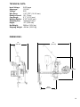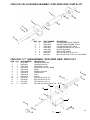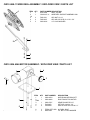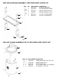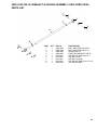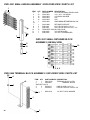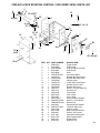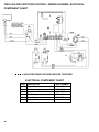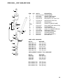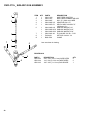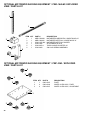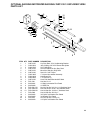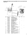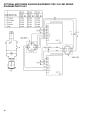
1
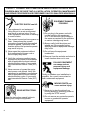
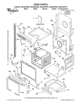
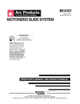
INSTRUCTIONS
AND
PARTS MANUAL
CW-18
CIRCLE WELDER
Please record your equipment identification information below for future reference. This information can be found
on your machine nameplate.
Model Number
Serial Number
Date of Purchase
Whenever you request replacement parts or information on this equipment, always supply the information you
have recorded above.
LIT-CW18-IPM-0810
CYPRESS WELDING EQUIPMENT INC.
A DIVISION OF WELD TOOLING CORPORATION
280 Technology Drive • Canonsburg, PA 15317-9564 USA
Telephone: 1-412-331-1776 • 1-800-245-3186 • Fax: 1-412-331-0383
http://www.cypressweld.com
PROTECT YOURSELF AND OTHERS FROM SERIOUS INJURY OR DEATH. KEEP
CHILDREN AWAY. BE SURE THAT ALL INSTALLATION, OPERATION, MAINTENANCE
AND REPAIR PROCEDURES ARE PERFORMED ONLY BY QUALIFIED INDIVIDUALS.
ELECTRIC SHOCK can kill.
1) The equipment is not waterproof. Using the unit in a wet environment may result in serious injury. Do not touch equipment when wet or standing in a wet location.
2) The unused connectors have power on them. Always keep the unused
connectors covered with the supplied protective panels. Operation of the machine without the protective panels may result in injury.
3) Never open the equipment without first unplugging the power cord or serious injury may result.
4) Verify the customer-supplied power connections are made in accordance with all applicable local and national electrical safety codes. If none exist, use International Electric Code (IEC) 950.
5) Never remove or bypass the equip-
ment power cord ground. Verify the equipment is grounded in accordance with all applicable local and national electrical safety codes. If none exist, use International Electric Code (IEC)
950.
READ INSTRUCTIONS.
Read the instruction manual before installing and using the equipment.
2
EQUIPMENT DAMAGE
POSSIBLE.
1) Do not plug in the power cord with
out first verifying the equipment is OFF and the cord input voltage is
the same as required by the machine
or serious damage may result.
2) Always verify both the pinion and wheels are fully engaged before
applying power or equipment damage
may occur.
3) Do not leave the equipment
unattended.
4) Remove from the worksite and store in a safe location when not in use.
FALLING EQUIPMENT
can cause serious
personal injury and
equipment damage.
Faulty or careless user installation is
possible. As a result, never stand or
walk underneath equipment.
MOVING PARTS can
cause serious injury.
1) Never try to stop the pinion from
moving except by removing power or by using the STOP control.
2) Do not remove any protective panels, covers or guards and operate
equipment.
HIGH FREQUENCY WARNINGS
SPECIAL PRECAUTIONS ARE REQUIRED WHEN USING PLASMA,
TIG OR ANY WELDING PROCESS THAT USES HIGH FREQUENCY
TO STRIKE AN ARC.
WARNING: HIGH FREQUENCY CAN EFFECT MACHINE OPERATION AND THEREFORE, WELD QUALITY.
Read the precautions below before installing and using the equipment.
PRECAUTIONS:
1)Some plasma or welding cables are strong sources of high frequency interference. NEVER lay a plasma or welding cable across the controls of the machine.
2) Always physically separate the plasma or welding cable leads from the machine cables. For example, the plasma or welding cable leads should NEVER be bundled with a pendant cable or the machine power cord. Maximize the separation between any machine cables and the plasma or welding cables.
3) Strictly follow the grounding procedures specified for the plasma or welding unit. NOTE: Some plasma and welding units produce exceptionally large amounts of high frequency noise. They may require a grounding rod be driven into the earth within six feet (2 meters) of the plasma or welding unit to become compatible with an
automatic cutting or welding process.
4) If the high frequency is produced using a spark gap, adjust the points so the gap is as small as possible. The larger the gap, the higher the voltage and the higher the interference.
5) Some plasma or welding units will inject high frequency interference into the AC power line. Use separate power line branches whenever possible to power the plasma
or welding source and the machine. Do not plug them into the same outlet box.
6) High frequency noise may enter the machine through the plasma or welding supply remote contactor leads. Some plasma and welding sources can produce noise spikes
of up to several thousand volts. These sources are not compatible with automated cutting and welding equipment. It is recommended that the remote contactor leads on these plasma or welding sources not be connected to the machine. An alternate
solution is to purchase a separate remote contactor isolation box.
3
4
CW-18 CIRCLE WELDER
INSTRUCTIONS AND PARTS MANUAL
TABLE OF CONTENTS
PAGE
6......... Introduction / Set-up and Operation
8......... LDC-NA3S NA-3 Wire Feeder Controls
10........ CWO-6210-CW18 Rotation Controls
11........ Technical Data / Dimensions
12........ CWO-1800 CW-18 Circle Welder / Parts List
13........ CWO-1800 CW-18 Circle Welder / Exploded View
14........ CWO-1800 CW-18 Circle Welder / Wiring Diagram / Electrical Component Chart
15........ CWO-3133 CW-11/CW-18 Collector with Power Racker
16........ CWO-1840 CW-18 Racking System / Exploded View / Parts List
16........ CWO-1690 Horizontal Racker / Exploded View / Parts List
17........ CWO-3165 CW-18 Housing Assembly / Exploded View / Parts List
17........ CWO-3205-11 7" Cam Assembly / Exploded View / Parts List
18........ CWO-3313 Brush Holder & Support Assembly / Exploded View / Parts List
18........ CWO-3359 Transmission 5:1 / Exploded View / Parts List
19........ CWO-3432 CW-18 Shaft Assembly / Exploded View / Parts List
19........ CWO-3490 Flux Hopper Assembly / Exploded View / Parts List
20........ CWO-3498-11 Wire Reel Assembly / Exploded View / Parts List
20........ CWO-3506 4066 Motor Assembly / Exploded View / Parts List
21........ CWO-3528 2" Flange Bearing w/Fasteners / Exploded View / Parts List
21........ CWO-3531 Motor & Transmission Plate Assembly / Exploded View / Parts List
22........ CWO-3534 Slide Bar Assembly / Exploded View / Parts List
22........ CWO-3537 Guard Assembly CW-18 / Exploded View / Parts List
23........ CWO-3538 CW-18 Camshaft & Spacer Assembly / Exploded View / Parts List
24........ CWO-3931 Small Brush Assembly / Exploded View / Parts List
24........ CWO-3969 Terminal Block Assembly / Exploded View / Parts List
25........ CWO-3971 Control Cable / Detail View / Parts List
25........ CWO-2978 Feeder Control Box Cable / Detail View / Parts List
26........ CWO-3974 33# Load Spring Assembly / Exploded View / Parts List
27........ CWO-6210-CW18 Rotation Control / Exploded View / Parts List
28........ CWO-6210-CW18 Rotation Control / Wiring Diagram / Electrical Component Chart
29........ CWO-3690-_ K231 Sub Arc Gun
30........ CWO-3710-_ Sub Arc Gun Assembly
31........ 3-Jaw Expandable Chucks
32........ Optional Motorized Racking Equipment / CWO-1640-M / Exploded View / Parts List
32........ Optional Motorized Racking Equipment / CWP-3363 / Exploded View / Parts List
33........ Optional Motorized Racking Equipment / CWP-3351 / Exploded View / Parts List
34........ Optional Motorized Racking Equipment / PRS-1075 / Exploded View / Parts List
35........ Optional Motorized Racking Equipment / PRS-1100 / Exploded View / Parts List
36........ Optional Motorized Racking Equipment / PRS-1091-WD Wiring Diagram / Parts List
37........ Preventative Maintenance / CW-18 Circle Welder
40........ Warranty
Patents Pending
5
INTRODUCTION
The CW-18 (CWO-1800) Circle Welder is designed for welding of nozzles into vessels or
domed heads utilizing SUB-ARC, MIG or FLUX CORED PROCESS, with gas shielding. The
CW-18 mounts on a 3-Jaw Chuck welding diameter 6” to 50” O.D.
Features:
•
•
•
•
•
•
•
•
•
•
•
•
•
•
Wire feeder with one set of drive rolls.
1/12 HP P.M. motor and rotational speed control.
600 AMP gun & cable assembly.
Internal to NA3
50 ft. (15 m) power cable.
50 ft. (15 m) gas shielding hose.
50 ft. (15 m) weld cable.
Quick disconnects for all cables.
Pre and post flow controls.
Wire reel adaptor for 60 lb. (27 kg) spools.
Adjustable vertical and horizontal torch positioning system.
Rise and fall cam assembly with 5” (125 mm) of travel.
Brushes and collector rings for welding current, rated at 600 AMPS 100% duty cycle.
Brushes and collector rings for all controls, eliminates cable and hose wrap.
NA 3 Control Provides:
•
•
•
•
•
•
•
Wire Spool (amperage) control
Voltage Control
Wire burn back
Weld contact
Cold wire switch
Weld start parameter adjustment
Weld Crater parameter adjustment
SET-UP AND OPERATION:
POWER SOURCE:
Please refer to the included Lincoln NA3 user’s manual for welding power source requirements
and system set-up.
GUNS AND CABLES:
All circle welders come equipped with a gun and cable assembly. It is our recommendation that
at least once a week the liner be taken out of the cable and soaked overnight in a solvent solution. To keep the wire moving it is also recommended that a felt clip be saturated with a product
like Ferro Slick and feed through the incoming tube of the wire feeder at least once a day.
ADDITIONAL CABLES:
The circle welders are supplied with the following cables:
1. CWO-3971 50’ (15 m) power cable that connects the power source to the cable
connector on the top gear of the machine.
2. CWO-3040 50’ (15 m) weld cable that connects the lead coming out of the top of the
machine using the quick connect connector to your power supply.
3. CWO-9406 50’ (15 m) gas shielding hose that connects the gas fitting on the top of the shaft to your shielding gas supply.
6
SET-UP AND OPERATION CONTINUED:
WIRE SPEED AND VOLTAGE ADJUSTMENT:
The wire speed control on the front of the LDC-NA3S Wire Feed Control box has a dial that is
calibrated directly in inches per minute. Set the voltage using the control on the power source.
RISE AND FALL OF THE CAM:
All circle welders are equipped with a rise and fall cam assembly. The cam assembly must be aligned before any other
settings can be made. To align the cam rotate the machine so
the horizontal rack is parallel to the pipe, then adjust the gun
holder so it is perpendicular to the horizontal rack. Position
torch tip to top dead center of joint. Loosen the set screws in
the brass block on the cam, and rotate the cam to the vertical
position as shown. Refasten set screws.
Cam
CAM SETTING:
The cam setting is equal to distance “B” subtracted from
distance “A”.
Example:
Let A=3 and B=2
3-2=1
The cam setting is 1.
B A
B A
Torch
Holder
WHEEL ADJUSTMENT:
The CW-18 Racking System CWO-1840 and the Small Vertical Racker
CWO-1690 are equipped with adjustable wheels. Always check these
components for proper wheel adjustment before using the machine. The
wheels need adjustment if you can cock or wiggle the components out of
alignment. The wheels should be snug but not prohibit movement along
the path of travel. The wheels with the hex stand offs are adjustable. To
adjust the wheels, loosen the hex bolt (A) until the adjustable bushing (B)
can be rotated. Correct the wheel alignment by rotating the adjustable
bushing (B). Once adjusted, hold the adjustable bushing (B) while
tightening the hex bolt (A). Recheck alignment.
Pipe
B
A
MACHINE CONTROLS:
Operational parameters can be set using the two control boxes. Please
refer to the section in this manual entitled CWO-6210-CW18 Rotational
Control for descriptions of the various speed and directional capabilities. For the LD-NA3S NA-3 Wire
Feeder Control; refer to the supplied NA-3 Semiautomatic Wire Feeder Manual from Lincoln Electric.
MAKING A WELD:
1. Position the gun to start position using the CWO-1840 Racking System.
2. Connect the ground cable to the workpiece. The ground cable must make good electrical
contact with the work.
3. Position the electrode in the joint. The end of the electrode may be lightly touching the work.
4. With manual/auto switch in the “OFF” position, set rotation direction and speed.
5. Weld process and rotation are both started by throwing the manual/auto switch to auto.
6. Weld process and rotation are stopped by throwing the manual/auto switch to “OFF”.
7
LDC-NA3S NA-3 WIRE FEEDER CONTROLS
J
A
I
H
B
G
C
F
A.
B.
C.
D.
E.
F.
G.
H.
I.
J.
8
Ammeter
Circuit breaker
Voltmeter
D
Start
Stop
Inch up and inch down
Current control
Travel
Voltage control
Control power
E
LDC-NA3S NA-3 WIRE FEEDER CONTROLS, CONT’D.
NOTE: For further information refer to Lincoln Electric NA-3 Operator’s Manual.
A. AMMETER
Indicates current only while welding.
B. CIRCUIT BREAKER
Protects the circuit from sever wire feed motor overload and short circuits. Press to reset.
Locate and correct the cause for overload.
C. VOLTMETER (Standard)
Indicated welding voltage only while welding. Also indicates OCV below 60 volts.
D. START
Push-button beings the welding cycle
E. STOP
Push-button initiated the stopping cycle at the end of the weld.
F. INCH UP & INCH DOWN
Press to inch electrode at the speed set by “Inch Speed” control on inner panel.
G. CURRENT CONTROL
Adjusts wire feed speed to control welding current.
H. TRAVEL
Turn to “Off” for no travel; “Hand Travel” for travel without welding; “Automatic Travel” for
welding operations. Speed and direction of travel are controlled by the travel mechanisms
control.
I. VOLTAGE CONTROL
Adjust arc volts by controlling power source output voltage.
J. CONTROL POWER
Turns input control power “On” and “Off”. Also used as an emergency “Off” in case of
malfunction.
*For further information on NA-3 Wire Feeder and controls, refer to Lincoln Electric NA-3
Wire Feeder Operators Manual.
9
CWO-6210-CW18 ROTATION CONTROLS
Speed Control
Travel Direction
On/Off Switch
Pilot Light
SPEED CONTROL:
Controls the speed in which the machine travels. The depicted lines 0 to 100 should not be construed as inches per minute of travel. They should be considered as reference points only.
TRAVEL DIRECTION:
Controls the direction in which the machine will travel. Select forward for clockwise rotation,
brake for stop, and reverse for counterclockwise rotation.
ON/OFF SWITCH:
The on/off switch enables/disables power to the rotation control box.
PILOT LIGHT:
The pilot light indicates whether the machine is on/off as dictated by the on/off switch.
10
TECHNICAL DATA
Input Voltage:
0-600 amps
Amperage:
115 VAC
Voltage:
0-50
Wire Sizes:
1/16’’-7/32’’ (1.6-5.6 mm)
Rotation Speed: .06-.72 rpm
Cam Range:
0’’-7’’ (0-175 mm)
Welding Radius: 0’’-25” (0-635 mm)
Shielding Gas:
Solenoid Control
Height:
43’’ (1092 mm)
Net Weight:
360 lbs. (163.6 kg)
Shipping Weight: 490 lbs. (222.3 kg)
DIMENSIONS:
70”
(1778 mm)
36”
(914 mm)
43”
(1092 mm)
36.5”
(927 mm)
11
CWO-1800 CW-18 CIRCLE WELDER / PARTS LIST
ITEM
1
2
3
4
5
6
7
8
9
10
11
12
13
14
15
16
17
18
19
20
21
22
23
24
25
26
27
28
29
30
31
32
33
34
35
36
37
38
QTY
1
1
1
1
1
1
1
1
1
1
1
1
1
1
1
1
1
1
1
1
1
2
1
1
1
1
1
1
1
1
1
1
1
1
1
1
1
1
12
PART NUMBER
CWO-1123
CWO-1124
CWO-1690
CWO-1811
CWO-1812
CWO-1813
CWO-1814
CWO-3133
CWO-1816
CWO-3931
CWO-1840
CWO-2020
CWO-3165
CWO-3205-11
CWO-3218
CWO-3312
CWO-3313
CWO-3359
CWO-3432
CWO-3498-11
CWO-3506
CWO-3528
CWO-3531
CWO-3534
CWO-3537
CWO-3538
CWO-3690-5/32
CWO-3695-1/2
CWO-3697
CWO-3968
CWO-3969
CWO-4900
CWO-5074
CWO-5793
CWO-6210-CW18
LDC-0010
LDC-NA3S
CWO-1820
DESCRIPTION
CONTROL MT. SPACER BLOCK
CW-18 CONTROL MT. PLATE
LARGE HORIZONTAL RACK
NA-3S MOUNT PLATE
FLUX HOPPER SUPPORT
WIRE FEEDER BRACKET
INSULATOR PLATE
COLLECTOR, CW-11/CW-18
WIRE FEEDER ADAPTOR
BRUSH RETAINER ASSEMBLY
CW-18 RACKING SYSTEM
FLUX RECOVERY SYSTEM (OPTIONAL)
CW-18 HOUSING ASSEMBLY
7’’ CAM ASSEMBLY CW-18
CABLE SUPPORT BAR
LIFTING LUG WELDMENT
BRUSH HOLDER & SUPPORT
TRANSMISSION SW-5:1 ASSEMBLY
CW-18 SHAFT ASSEMBLY
WIRE REEL ASSEMBLY CW-18
4066 MOTOR ASSEMBLY
2’’ FLANGE BEARING W/ FASTENERS
MOTOR & TRANSMISSION PLT. ASSEMBLY
SLIDE BAR MOUNTING ASSEMBLY
GUARD ASSEMBLY CW-18
CW-18 CAMSHAFT & SPACER ASSEMBLY
SUB-ARC NOZZLE
ADAPTOR K231 1/2’’
QCC 72’’ LINER
CW-18 BASE PLATE
TERMINAL BLOCK ASSEMBLY
33# LOAD SPRING
1-1/2’’ ID TRANTORQUE
GEAR ALUMINUM
M-14 ROTATION CONTROL
NA-3 WIRE FEEDER ASSEMBLY
NA-3S WIRE FEEDER CONTROL
FLUX HOPPER SUPPORT ASSEMBLY
CWO-1800 CW-18 CIRCLE WELDER / EXPLODED VIEW
15
16
25
12
34
33
21
37
8
18
32
10
14
26
31
23
17
22
20
3
36
7
6
13
9
24
1
29
22
38
2
5
28
35
12
4
12
19
27
30
13
CWO-1800 CW-18 CIRCLE WELDER / WIRING DIAGRAM / ELECTRICAL
COMPONENT CHART
1
4
13
5
9
14
10
8
7
3
6
11
12
ELECTRICAL COMPONENT CHART
14
ITEM
1
2
3
4
5
6
7
8
9
10
11
12
13
14
DESCRIPTION
PART NUMBER
NA-3 Wire Feeder
LDC-0010
Weld Cable 4/0 50’
CWO-3040
Collector for CW-11/CW-18 CWO-3133
Brush Holder Support
CWO-3313
4006 Motor Assy.
CWO-3506
NA-3 Wire Feeder Control
LDC-NA3S
Small Retainer Brush CWO-3931
Terminal Block Assy.
CWO-3969
Weld Cable 4/0
CWO-3970
Weld Cable Inlet 4/0
CWO-3972
Feeder Control Box Cable
CWO-2978
M-14 Rotational Control
CWO-6210-CW18
K231 Sub Arc Gun
CWO-3710-_
Weld Cable 4/0 6’
CWO-3970-72
2
CWO-3133 CW-11/CW-18 COLLECTOR WITH POWER RACKER
2
6
14, 21
3
10
4
9, 18, 22
5
19
15
12, 16 (4X)
1
7 8
13, 17 (4X)
23
11
15
ITEM QTY
1
1
2
12
3
1
4
13
5
1
6
1
7
1
8
1
9
2
10
1
11
1
12
4
13
4
14
1
15
4
16
4
17
4
18
2
19
1
20
1
21
1
22
2
23 140’’
PART NUMBER DESCRIPTION
BUG-1034
PANEL CONNECTOR 4-T, M
CWO-3127
BRASS RING 4.250’’ DIA X .188’’ THK
CWO-5739
BRASS RING 4.250’’ DIA X 3.750 THK
CWO-5744
MICARTA SPACER
CWO-5745
TOP COLLECTOR PLATE
CWO-5746
CB-2 BOTTOM COLLECTOR PLATE
CWO-5747
MICARTA SPACER W/NOTCH
CWO-5758
MICARTA SLEEVE .495’’ O.D. X 391’’ I.D. X 4.500’’ LG
CWO-5760
MICARTA SLEEVE .495’’ O.D. X .391 I.D. X 8.000’’ LG
CWO-5770
MICARTA SLEEVE 1.875’’ O.D. X 1.5000’’ I.D. X 7.750’’ LG
CWO-6068
PANEL CONNECTOR 9-T, M
FAS-0205
RND HD SCR 4-40 X 1/2’’
FAS-0215
RND HD SCR 6-32 X 1/2’’
FAS-0397
HEX HD CAP SCR 3/8-16 X 3/4’’
FAS-0455
SET SCR 1/4-20 X 1/2’’ CUP POINT
FAS-1305
HEX NUT 4-40
FAS-1310
HEX NUT 6-32
FAS-3397
HEX HD CAP SCR 3/8-16 X 8-1/2’’
TERM-5494
#8 RING, RED
W05-2025
GREEN WIRE 20 GA 2-1/2’’
WAS-0260
3/8’’ WASHER
WAS-0262
3/8’’ SPLIT LOCKWASHER
WRE-1601
16 AWG. WHITE TEFLON
15
CWO-1840 CW-18 RACKING SYSTEM / EXPLODED VIEW / PARTS LIST
2
1
ITEM QTY PART NUMBER DESCRIPTION
1
1
ABR-1050
V-GUIDE WAYS 40”
2
1
ABR-1060
V-GUIDE WAYS 33”
3
1
CWO-1675
VERTICAL RACKER
4
1
CWO-1695
ATTACHMENT BLOCK
5
1
CWO-3023-S
TORCH ANGLE ADJUSTER 6
1
CWO-3460
33# LOAD SPRING ASSY.
4
3
6
5
CWO-1690 HORIZONTAL RACKER / EXPLODED VIEW / PARTS LIST
10
17
1
2
16
13
14
12
3
15
5
F
F
A
A
11
4
7
A
16
6
9
F
A
F
8
ITEM QTY PART NUMBER DESCRIPTION
1
1
BUG-2032
KNOB, BLACK
2
1
CWO-1671
RACKER SHIELD
3
1
CWO-1678
RACKER PLATE
4
1
CWO-1679
PINION 11T
5
2
CWO-1680
W2 FIXED LEG & WHEEL ASSY.
6
2
CWO-1681
W2 ADJ. LEG & WHEEL ASSY.
7
1
CWO-1687
MOUNT PLATE (LARGE RACKER)
8
2
CWO-4326
FIXED LEG & WHEEL ASSY.
9
2
CWO-4327
ADJ. LEG & WHEEL ASSY.
10
2
FAS-0559
SOC HD CAP SCR 1/4-20 X 1”
11
1
FAS-1307
HEX JAM NUT 3/4-16
12
1
MUG-1141
BEARING COLLET
13
1
MUG-1142
KNOB, LOCKING
14
1
MUG-1144
SHAFT
15
2
MUG-1453
STAND-OFF
16
1
MUG-1579
RETAINING RING
17
3
WAS-0240
1/4” SAE WASHER
F= FIXED WHEEL PLACEMENT
A= ADJUSTABLE WHEEL PLACEMENT
CWO-3165 CW-18 HOUSING ASSEMBLY / EXPLODED VIEW / PARTS LIST
8
1
4
5
3
7
2
6
5
8
ITEM QTY PART NUMBER DESCRIPTION
1
1
CWO-4133
1/4-18 NPSM HEX PLUG, BRASS
2
1
CWO-5842
CENTER TUBE HOUSING, CW-18
3
1
CWO-5845
TOP HOUSING PLATE, CW-18
4
1
CWO-5853
LOWER HOUSING PLATE, CW-18
5
2
CWO-5980
PLASTIC BUSHING
6
3
CWO-9339
ANGLE FOR GUARD
7
3
FAS-0535
SOC HD CAP SCR 10-24 X 1/2”
8
8
FAS-0548
SOC HD CAP SCR 10-32 X 3/4” LOW HEAD
CWO-3205-11 7" CAM ASSEMBLY / EXPLODED VIEW / PARTS LIST
ITEM QTY
1
2
2
1
3
2
4
1
5
1
6
1
7
1
8
2
9
1
10
4
11
1
12
2
13
4
PART NUMBER
BUG-2098
BUG-9012
CWO-4027
CWO-4330
CWO-4032
CWO-4328
CWO-4331
CWO-4332
CWO-5199
FAS-0434
FAS-0444
FAS-0495
FAS-0534
DESCRIPTION
DELRIN WASHER 3/8”
LOCKING COLLAR
END PLATE 4” CAM
CENTER BLOCK .625” BORE
KNOB
BASE PLATE ROD
SCREW ROD
ROD
SCALE
SET SCR #10-24 X 3/8”
SET SCR #10-32 X 3/8”
SET SCR 3/8”-16 X 1/2”
SOC HD CAP SCR #10-24 X 3/8”
12
2
10
1
4 3
8
10
3
7
6
11
1
5
9
13
17
CWO-3313 BRUSH HOLDER & SUPPORT ASSEMBLY / EXPLODED VIEW /
PARTS LIST
2
10
2
9
8
2
11
12
1
1
4
1
3
5
6
13
7
12
5
ITEM QTY
1
3
2
6
3
1
PART NUMBER
CWO-4046
CWO-4337
CWO-4472
DESCRIPTION
LARGE BRUSH HOLDER
LARGE BRUSH 1-1/2” X 3/4” X 2”
BRUSH HOLDER SUPPORT CW-18
CWO-4473
CWO-5548
CWO-5549
FAS-0305
FAS-0309
FAS-0357
FAS-3304
WAS-0243
WAS-0280
WAS-0281
ATTACHMENT BAR CW-18
MICARTA SPACER
MICARTA BUSHING
HEX HD CAP SCR 1/2-13 X 2”
HEX HD CAP SCR 1/2-13 X 1”
HEX HD CAP SCR 1/4-20 X 3/4”
HEX HD CAP SCR 1/2-13 X 4”
1/4” SPLIT LOCKWASHER
1/2” SAE WASHER
1/2” SPLIT LOCKWASHER
4
5
6
7
8
9
10
11
12
13
1
2
1
1
1
4
1
4
3
3
CWO-3359 TRANSMISSION 5:1 / EXPLODED VIEW / PARTS LIST
ITEM QTY PART NUMBER
DESCRIPTION
1
1
CWO-4347
TRANSMISSION 5:1
2
4
FAS-0359
HEX HD CAP SCR 1/4-20 X 1”
3
4
FAS-1351
1/4-20 HEX NUT
4
4
WAS-0240
1/4” SAE WASHER
5
4
WAS-0243
1/4” LOCK WASHER
6
1
UNI-1024
SLAVE PINION
3
5
1
4
2
6
18
CWO-3432 CW-18 SHAFT ASSEMBLY / EXPLODED VIEW / PARTS LIST
1
2
ITEM
1
2
3
QTY
1
2
1
PART NUMBER
BUG-9096
CWO-4507
CWO-5779
2
3
DESCRIPTION
OUTLET BUSHING, OXYGEN
O-RING, OXYGEN, GAS
SHAFT CW-18
CWO-3490 FLUX HOPPER ASSEMBLY / EXPLODED VIEW / PARTS LIST
ITEM
1
2
3
4
5
N/S
QTY
1
1
1
1
1
1
PART NUMBER
CWO-3757
CWO-3760
CWO-3478
CWO-3769
GOF-3019
CWO-3491-48
DESCRIPTION
HOPPER SUPPORT ROD
CLAMP BLOCK 1/2”
1-3/4” HOSE BARB
FLUX HOPPER STEEL 12”
HANDLE W/ BOLTS
FLUX HOSE 3/4” ID X 1” OD X 48” LG
5
4
1
3
2
19
CWO-3498-11 WIRE REEL ASSEMBLY / EXPLODED VIEW / PARTS LIST
1
ITEM QTY
1
1
2
1
18
3
2
4
2
5
2
PART NUMBERDESCRIPTION
BUG-3293
REEL, 60 LBS.
CWO-3217-11 WIRE REEL SUPPORT ASSEMBLY CWFAS-1301
FAS-2305
WAS-0281
HEX NUT 1/2-13
HEX HD CAP SCR 1/2-13 X 1-3/4”
1/2” LOCK WASHER
4
2
5
3
CWO-3506 4066 MOTOR ASSEMBLY / EXPLODED VIEW / PARTS LIST
4
2
3
6
1
7
5
20
ITEM QTY
1
1
2
1
4066
3
1
4
1
5
4
6
7
3
4
PART NUMBER
CWO-3620
CWO-4846
DESCRIPTION
MOTOR MOUNT BRACKET
RIGHT ANGLE DC MOTOR
CWO-5767
FAS-0453
FAS-0559
GEAR PM MOTOR 147
SET SCR 1/4-20 X 1/4”
SOC HD CAP SCR 1/4-20 X 1”
TERM WTE 1508 #8 FORK, BLUE
WAS-0243
1/4” SPLIT LOCK WASHER
CWO-3528 2” FLANGE BEARING w/FASTENERS / EXPLODED VIEW / PARTS
LIST
ITEM
1
2
3
4
5
6
2
5
6
1
QTY
1
1
2
2
2
2
PART NUMBER
CWO-1511
CWO-4482
FAS-1398
FAS-3305
WAS-0290
WAS-0291
DESCRIPTION
1/8” PIPE PLUG BLACK IRON
FLANGE BEARING 2” BORE
9/16-12 HEX NUT
HEX HD CAP SCR 9/16-12 X 2”
9/16” SAE WASHER
9/16” SPLIT LOCK WASHER 3
CWO-3531 MOTOR & TRANSMISSION PLATE ASSEMBLY / EXPLODED VIEW
/ PARTS LIST
ITEM
1
2
3
4
5
6
7
8
9
10
11
12
13
QTY
1
1
1
1
5
8
3
2
4
5
5
4
8
PART NUMBER
BUG-1338
CWO-5788
CWO-5887
CWO-5888
FAS-0359
FAS-1390
FAS-2372
FAS-2374
FAS-2398
WAS-0243
WAS-0251
WAS-0260
WAS-0262
DESCRIPTION
I.D. PLATE
COVER PLATE
MOTOR & TRANSMISSION PLATE
END PLATE
HEX HD CAP SCR 1/4-20 X 1”
HEX NUT 3/8-16
HEX HD CAP SCR 5/16-18 X 1-1/4”
HEX HD CAP SCR 5/16-18 X 1-3/4”
HEX HD CAP SCR 3/8-16 X 3”
1/4” SPLIT LOCK WASHER
5/16” SLPIT LOCK WASHER
3/8” WASHER
3/8” SPLIT LOCK WASHER
6
5
4
6
5
7
5
3
2
9
1
7
8
8
7
21
CWO-3534 SLIDE BAR ASSEMBLY / EXPLODED VIEW / PARTS LIST
ITEM QTY
1
1
2
2
PLATE
3
2
4
4
1-1/4”
5
4
6
2
4
PART NUMBER DESCRIPTION
CWO-3912
SLIDE BAR ASSEMBLY
CWO-9033
TOP / BOTTOM VERTICAL SLIDE
FAS-0399
FAS-2372
HEX HD CAP SCR 3/8-16 X 1”
HEX HD CAP SCR 5/16-18 X
WAS-0251
WAS-0262
5/16” SPLIT LOCKWASHER
3/8” SPLIT LOCKWASHER
5
1
2
6
2
3
CWO-3537 GUARD ASSEMBLY CW-18 / EXPLODED VIEW / PARTS LIST
1
3
5
ITEM
1
18
2
3
4
5
2
4
22
QTY PART NUMBERDESCRIPTION
1
CWO-5094
UPPER GUARD CB-2, CB-3, CW-7, CW1
4
3
4
CWO-9142
FAS-1376
FAS-1455
FAS-0261
LOWER GUARD CW-18
RIVET 1/8” DIA X 3/8”
T.C. SLT HEX 1/4-20 X 1/4” w/WASHER
3/8” WASHER / .056 THK
CWO-3538 CW-18 CAMSHAFT & SPACER ASSEMBLY / EXPLODED VIEW /
PARTS LIST
8
1
7
9
3
4
6
5
2
9
9
ITEM
1
2
3
4
5
6
7
8
9
QTY
1
1
1
1
1
2
1
1
3
PART #
CWO-4352
CWO-5042
CWO-9081
CWO-9353
FAS-0399
FAS-1395
FAS-1396
FAS-2396
WAS-0260
DESCRIPTION
BALL JOINT END 3/8-16 R.H.
BALL JOINT END 3/8-16 L.H.
SPACER CW-18
PIPE FOR CAM SHAFT CW-18
HEX HD CAP SCR 3/8-16 X 1”
HEX NUT 3/8-24
HEX NUT 3/8-24 LH
HEX HD CAP SCR 3/8-16 X 2-1/4”
3/8” SAE WASHER
23
CWO-3931 SMALL BRUSH ASSEMBLY / EXPLODED VIEW / PARTS LIST
1
ITEM
1
2
3
4
5
6
18
7
8
9
10
11
12
1
7
QTY
1
12
12
12
12
1
PART NUMBER
CWO-3947
CWO-5831
CWO-5874
CWO-5875
CWO-5876
CWO-9067
DESCRIPTION
12 POSITION SMALL BRUSH ASSY
1/8” x 1/8” x 1/8” BRUSH
1/8” BRUSH HOLDER
CAP
CLIP
SMALL BRUSH RETAINER BLOCK, CW-
1
2
1
12
1
1
CWO-9082
RETAINER SUPPORT
FAS-0359
SOC HD CAP SCR 10-24 X 1”
FAS-0593
SOC HD CAP SCR 3/8-16 X 1-1/2”
TERM-WTE-1508 #8 FORK, BLUE
WAS-0260
3/8” SAE WASHER
WAS-0262
3/8” SPLIT LOCKWASHER
8
CWO-3931 SMALL RETAINER BLOCK
ASSEMBLY / DETAIL VIEW
11
10
12
9
6
2, 3, 4, 5
CWO-3969 TERMINAL BLOCK ASSEMBLY / EXPLODED VIEW / PARTS LIST
4
ITEM QTY PART NUMBER DESCRIPTION
1
1
CWO-6726
TERMINAL BLOCK 14-PIN
2
1
CWO-9071
TERMINAL BLOCK
SUPPORT CW-18
3
2
FAS-0215
RND HD SCR 6-32 X 1/2”
4
1
FAS-0356
HEX HD CAP SCR 1/4-20 X 5/8”
2
5
5
3
1
24
3
1
WAS-0243
1/4” SPLIT LOCK WASHER
CWO-3971 CONTROL CABLE / DETAIL VIEW / PARTS LIST
ITEM
1
2
3
QTY
600”
1
1
4
9
PART NUMBER
900-4-016
BUG-5552-B
BUG-6069-P
DESCRIPTION
16/10 SO CABLE
CABLE CLAMP
CABLE CONNECTOR 9-T, F
TERM-WTE-0602 #6 FORK, BLUE
CWO-2978 FEEDER CONTROL BOX CABLE / DETAIL VIEW / PARTS LIST
ITEM
1
2
3
4
QTY
32”
1
1
9
PART NUMBER
900-4-016
BUG-5552-B
BUG-6069-P
TERM-WTE-0602
DESCRIPTION
16/10 SO CABLE
CABLE CLAMP
CABLE CONNECTOR 9-T, F
#6 FORK, BLUE
25
CWO-3974 33# LOAD SPRING ASSEMBLY / EXPLODED VIEW / PARTS
2
1
3
8
2
1
3
6
8
5
9
4
7
10
ITEM QTY
1
2
3
4
5
6
7
8
9
10
26
2
2
2
1
1
2
1
2
1
1
PART #
CWO-4074
CWO-5707
CWO-5773
CWO-9230
FAS-0357
FAS-0555
FAS-1351
FAS-2697
WAS-0240
WAS-0243
DESCRIPTION
SPRING 16.5#
COLLAR W/ SET SCREW
INSERT 1-1/2” OD
SPRING RETAINER ANGLE
HEX HD CAP SCR 1/4-20 X 3/4”
SOC HD CAP SCR 1/4-20 X 1/2”
HEX NUT 1/4-20
SOC HD SHR 1/2 X 2 X 3/8-16
1/2 SAE WASHER
1/4” SPLIT LOCK WASHER
CWO-6210-CW18 ROTATION CONTROL / EXPLODED VIEW / PARTS LIST
3
2
13
13,14,21
23
20 (x3)
22
12
6 (x2)
15, 17
21, 14, 13
14
11
24
15, 16
21
7
21
19
(x10)
29
13
8
29
14
27
10
4
18
1
ITEM QTY PART NUMBER
1
1 ARM-2279
2
1 BUG-9445
3
1 CON-PS04M
4
1 BUG-9687
5
1 BUG-9694
6
2 CSR-WTE-1597
7
1 CWO-6216
8
1 CWO-5547B
9
1 CWO-6206
10
1 CWO-6527
11
1 CWO-6839
12
1 CWO-6802
13
6 FAS-0115
14
6 FAS-1310
15
2 FHO-0188
16
1 MPD-1026
17
1 FUS-0257
18
1 MUG-1258-1
19
10 SCW-WTE-0264
20
3 TERM-WTE-0197
21
6 WAS-0211
22
42’’ WRE-WTE-0501
23
1 MUG-1589
24
1 BUG-1562
25
4 FAS-0401
26
4 SCF-1001
27
1 BUG-1764
28
1 MDS-1011
29
6 BUG-3331
9
5
28
25, 26 (x4)
DESCRIPTION
Toggle Switch
Power Cord
Plug, Straight 4-Pin Male
Knob Fluted
Knob
Cord Strain Relief
Rotation Box Front Panel
Rotation Box Rear Panel
Indicator Light
0-90V Spd Ctrl w/Isolator
Rotation Control Case
Rotation Box Cover
#6-32 x 1/2” Pan Head Zinc
Hex Nut 6-32
Fuse Holder
Fuse 2 Amp
Fuse 3 Amp
Rotary Switch Assembly
#6-32 x 1/4” Sht Mt Scr
#6 Red Fork
#6 Internal Star Washer
18/3 SJO 300V Cord
Hole Plug .500’’
Multi-turn Potentiometer
#4-40 X 3/8’’ Pan Hd
#4-40 Self Clinching Nut
Meter Display Board
Display Bezel
Hole Plug 1/4’’
27
CWO-6210-CW18 ROTATION CONTROL / WIRING DIAGRAM / ELECTRICAL
COMPONENT CHART
3
6
2
5
1
4
= INDICATES ITEMS THAT ARE SUPPLIED TOGETHER.
ELECTRICAL COMPONENT CHART
ITEM
1
2
3
4
5
6
28
DESCRIPTION
Toggle Switch Red Neon Lamp
Speed Control Board w/Resistor
Fuse 2 amp
Fuse 3 amp
Rotary Switch
PART NUMBER
ARM-2279
CWO-6206
CWO-6525
MPD-1026
FUS-0257
MUG-1258-1
CWO-3690-_ K231 SUB ARC GUN
2
3
4
5
1
6
11A
11
7
ITEM QTY
1
1
2
1
3
1
4
1
13
5
1
6
1
*7
1
SIZE*)
8
1
9
1
10
1
11
1
11A
1
12
1
13
1
14
1
15
1
PART #
PXS-15106-3/32
PXT-10570
PXS-10493-1
PXS-121312
DESCRIPTION
NOZZLE INSERT
SOCKET HEAD SCREW
NOZZLE INSULATOR
HEX HD SCR 1 1/2’’ & NUT 1/2’’-
PXT-9967-10
CWO-8052
PXS-10125-_
NOZZLE BODY ROLL PIN
NOZZLE BODY
CONTACT TIP (SPECIFY WIRE
PXS-10138
PXT-9078-1
PXT-9967-30
PXT-13835
PXT-3835-IN
BUG-3161-P
BUG-3163
BUG-3164
BUG-3165
FLUX CONE PLUG (INSULATOR)
THUMB SCREW
FLUX CONE ROLL PIN
3/4’’X7’’ FLUX HOSE W/FBR INS
FIBER INSULATOR
CONE BODY ASSEMBLY
LOCKING FERRULE
FLUX CONE (KP2085-1)
RETAINING NUT
8
9
10
12
13
14
15
*WIRE SIZES AVAILABLE:
PART #
CWO-3690-1/16
CWO-3690-5/64
CWO-3690-3/32
CWO-3690-1/8
CWO-3690-5/32
CWO-3690-3/16
CWO-3690-7/32
WIRE SIZE
1/16’’ (1.6 mm)
5/64’’ (2.0 mm)
3/32’’ (2.4 mm)
1/8’’ (3.2 mm)
5/32’’ (4.0 mm)
3/16’’ (4.8 mm)
7/32’’ (5.6 mm)
*REPLACEMENT CONTACT TIPS AVAILABLE:
PART #
CWO-8048
CWO-8049
CWO-8050
CWO-8051
WIRE SIZE
5/64’’ (2.0 mm)
3/32’’ (2.4 mm)
5/32’’ (4.0 mm)
1/8’’ (3.2 mm)
PXS-10125XL-7/64
PXS-10125XL-1/16
PXS-10125XL-3/16
PXS-10125XL-7/32
7/64’’ (2.8 mm)
1/16’’ (1.6 mm)
3/16’’ (4.8 mm)
7/32’’ (5.6 mm)
29
CWO-3710-_ SUB ARC GUN ASSEMBLY
ITEM QTY PART #
1
1
CWO-1816
2
2
CWO-1817
3
1
CWO-3697
4
1
CWO-3695-1/2
5
1
CWO-3970-72
6
1
CWO-3690-1/8
1
CWO-3690-3/16
1
CWO-3690-5/32
7
1
CWO-3491-48
8
1
FAS-0452
9*
1
BUG-2708
1
2
3
7
2
5
4
8
6
30
DESCRIPTION
WIRE FEED ADAPTOR
BULK HEAD CONNECTOR QCB
QCC 72’’ (1829 mm) LINER
ADAPTOR K231 1/2’’
WELD CABLE 4/0 ASSY 72’’
(1829 mm) LG
SUB-ARC NOZZLE 1/8’’
SUB-ARC NOZZLE 3/16’’
SUB-ARC NOZZLE 5/32’’
FLUX HOSE 3/4” ID x 1” OD
SET SCR 1/4-20 X 1/4
CLAMP
*Item not shown in drawing.
DRIVE ROLLS
PART #
LDC-0013
LDC-0014
LDC-0015
DESCRIPTION
3/32’’-7/32’’ (2.4-5.6 mm) WIRE SIZES
1/16’’-3/32 (1.6-2.4 mm) WIRE SIZES
.035’’-.052’’ (.9-1.3 mm) SOLID WIRE
QTY
2
2
1
3-JAW EXPANDABLE CHUCKS
3-Jaw Expandable Chucks
Mounts and automatically centers the Circle Welder
on nozzles with or without flanges. As shown below.
CWO-3660
PART NUMBER
CWO-3660
CWO-3661
CWO-3362
CWO-3663
FOR NOZZLE I.D.’S
2”-8” (51-204 mm)
8”-16” (204-405 mm)
10”-24” (255-610 mm)
16”-42” (406-1065 mm)
WEIGHT
68 lbs. (31 kg)
36 lbs. (16 kg)
51 lbs. (23 kg)
64 lbs. (29 kg)
CWO-3661
CWO-3662
Options:
CWO-2020 Flux Recovery System
CWO-3663
31
OPTIONAL MOTORIZED RACKING EQUIPMENT / CWO-1640-M / EXPLODED
VIEW / PARTS LIST
2
1
3
4
6
ITEM QTY
1
1
2
1
3
1
4
1
5
1
6
1
PART #
ABR-1050-MH
ABR-1060-MV
CWO-1675-MV
CWO-1695
CWO-3023-1
CWO-3460
DESCRIPTION
MOTORIZED HORIZONTAL V-GUIDE WAYS 40”
MOTORIZED VERTICAL V-GUIDE WAYS 33”
MOTORIZED VERTICAL RACKER
ATTACHMENT BLOCK
TORCH ANGLE ADJUSTER 16”
33# LOAD SPRING ASSEMBLY
5
OPTIONAL MOTORIZED RACKING EQUIPMENT / CWP-3363 / EXPLODED
VIEW / PARTS LIST
2
3
2
ITEM QTY
1
1
2
4
3
4
3
1
2
3
3
32
2
PART #
CWO-1687
CWO-4326
CWO-4327
DESCRIPTION
PLATE
WHEEL & LEG ASSY., FIXED
WHEEL & LEG ASSY., ADJUSTABLE
OPTIONAL RACKING MOTORIZED RACKING/ CWP-3351 / EXPLODED VIEW /
PARTS LIST
2
11
12
13
3
4
1
10
21
8 20
19
18
16
17
6
5
7
11
13, 11
8
15
16
ITEM QTY PART NUMBER
1
1 CWP-3355
2
1 CWO-5933
3
2 CWO-5565
4
1 CWP-3354
5
1 CWP-3353
6
2 CWP-3362
7
1 CWO-3865
8
5 CWO-9038
9
2 CWO-9065
10
1 CWP-3356
11
6 FAS-1301
12
2 WAS-0281
13
4 WAS-0280
14
4 FAS-2591-SS
15
4 FAS-1444-SS
16
10 FAS-0359-SS
17
1 FAS-0399
18
1 WAS-0262
19
1 WAS-0260
20
4 FAS-0555
21
4 WAS-0243
9
14
DESCRIPTION
Hvy Duty Rack 150:1 No Mounting Bracket
Jaw Coupling 3/8" & 5/8" Bores With Spider
5/8" Pillow Block
Screw for Mtrzd Hrz Hvy Duty Rack
Mtrzd Hrz Slide Hvy Duty Rack
Stud 1/2-13 All Thread
1"-6 Acme Nut and Bar Assembly
Hold Down Clip
T-3 Track 36" Lg
Horiz P.M. Motor Bracket #970 Mod
Hex Nut 1/2-13
1/2 Split Lockwasher Zinc Plated
1/2 SAE Flat
Soc Hd Cap Scr 3/8-16 x 1-1/4 Stainless Steel
Phil Pan Hd Scr 10/32 x 3/8" Stainless Steel
Hex Hd Cap Scr 1/4-20 x 1" Stainless Steel
Hex Hd Cap Scr 3/8-16 x 1"
3/8" Split Lock Washer Zinc Plated
3/8 Washer Zinc Plated
Soc Hd Cap Scr 1/4-20 x 1/2
1/4" Split Lock Washer Zinc Plated
33
OPTIONAL MOTORIZED RACKING EQUIPMENT/ PRS-1075 / EXPLODED
VIEW / PARTS LIST
34
OPTIONAL MOTORIZED RACKING EQUIPMENT/ PRS-1100/ EXPLODED VIEW
/ PARTS LIST
ITEM Component Item
1
PRS-1111
2
BUG-2923
BUG-2952
BUG-2933
3
BUG-2924
4
BUG-5001
BUG-5002
BUG-5003
5
PRS-1110
6
PRS-1112
7
MUG-1156
8
BUG-1404
9
BUG-1411
10
BUG-1384
11
BUG-1383
BUG-1551
BUG-9636
12
BUG-9902
13
CAS-1770
14
BUG-9446
15
BUG-9445
GOF-3115
16
BUG-9628
17
FAS-0124
18
FAS-1320
19
WAS-0221
20
SCW WTE 0514
21
FAS-0204
22
FAS-1305
23
WAS-0201
24
FAS-0112
N/S
SFX-1292
Description
120vac
240vac
INPUT END PANEL
1
.7 AMP CIRCUIT BREAKER
1
.5 AMP CIRCUIT BREAKER
1
2 AMP CIRCUIT BREAKER
“RESET SEAL, TRANSPARENT”
1
TRANSFORMER 115VAC
1
TRANSFORMER 240VAC
1
TRANSFORMER 42VAC
ENCLOSURE
1
OUTPUT END PANEL
1
PANEL CONNECTOR, 4-T, F
1
RELAY BRACKET
1
HOLD DOWN SPRING
1
RELAY SOCKET & SPRING
1
RELAY, 4PDT, 3A 120V, PLUG IN
1
RELAY 3A, 240VAC
1
RELAY 48VAC
PANEL CONNECTOR, 6-T, F
1
SPEED CONTROL (IRON ROTOR) 2
CORD GRIP
1
POWER CORD (120VAC SHOWN)
1
LINE CORD 240VAC
1
CAP & CHAIN ASSY
1
8/32 X 3/8 PAN HD, Di-CHROME
10
HEX NUT 8-32
3
#8 INTERNAL STAR LOCKWASHER 3
#8-32 X 3/8" PAN HEAD, ZINC
1
RND HD SLT SCR 4-40 X 3/8 ZINC 8
HEX NUT 4-40
8
#4 INTERNAL STAR LOCKWASHER 8
PAN HD SLT 6-32 X 1/4 BLACK
6
BUMPER, CYLINDRICAL .14 X .50" 4
42vac
1
1
1
1
35
OPTIONAL MOTORIZED RACKING EQUIPMENT/ PRS-1091-WD WIRING
DIAGRAM/ PARTS LIST
36
PREVENTIVE MAINTENANCE / CW-18 CIRCLE WELDER
IMPORTANT: Make sure the input power at the power source is turned off and the 50’ weld
cable is disconnected from the circle welder prior to working inside the circle welder.
AFTER DAILY USE:
Refer to CW-18 Exploded View Parts List. (Pg. 12)
Large Horizontal Racker Item #3:
Inspect wheels and remove all dirt, grease, weld spatter and rust. Adjust wheels for snug fit and
smooth operation. Lubricate racker pinion and wheels with a dry teflon or graphite spray lubricant.
Racking System Item #11:
Inspect gear rack, hardened ways and wheels, remove all dirt, grease, weld spatter and rust.
Check hardened ways for nicks and replace if necessary. Lubricate with a dry teflon or graphite
spray lubricant. Adjust wheels for snug fit and smooth operation. Lubricate racker pinion with a
dry teflon or graphite spray lubricant.
Slide Bar Mounting Assembly Item #24:
Inspect hardened ways remove all dirt, grease and weld spatter. Check hardened ways for nicks
and replace if necessary. Lubricate with a dry teflon or graphite spray lubricant.
Refer to CW-18 Electrical Component Chart. (Pg. 14)
CW-18 Collector Item #3:
Inspect cable connector to make sure threads are not stripped and that the connector is not
cracked. Ensure that the connector is fastened properly to the large aluminum gear item #34 on
the CW-18 Exploded View Parts List.
NA-3 Control Cables:
For all cables leading to NA-3 Control box, inspect cable connector to make sure threads are not
stripped and that the connector is not cracked. Check the cable for cuts, missing insulation and
burn spots, replace if necessary.
EVERY SIX MONTHS:
Refer to CW-18 Exploded View Parts List. (Pg. 12)
7” Cam Assembly Item #14:
Inspect the slide rails and the cam pinion. Remove all dirt, grease and weld spatter. Do not
grease slide rails or cam pinion. Lubricate with a dry teflon or graphite spray lubricant. Replace
cam pinion if excessively worn. Tighten all fasteners as needed.
Wire Reel Assembly Item #20:
Periodically coat the wire wheel shaft with a thin layer of grease as needed. Inspect the shoe assembly and replace if excessively worn.
P.M. Motor Assembly Item #21:
Do not grease this pinion. Inspect the drive pinion. Remove all dirt, grease and weld spatter.
Lubricate with a dry teflon or graphite spray lubricant. Replace pinion if excessively worn. Check
set screw and tighten if necessary. Adjust motor assembly using the four adjustable mounting
fasteners so that proper gear mesh is achieved between the aluminum gear item #34 and the
motor drive pinion.
Aluminum Gear Item #34:
Do not grease this gear. Inspect gear teeth remove all dirt, grease and weld spatter. Lubricate
with a dry teflon or graphite spray lubricant. Replace gear if excessively worn.
37
PREVENTIVE MAINTENANCE / CW-18 CIRCLE WELDER, CONT’D.
Refer to CW-18 Electrical Component Chart. (Pg. 14)
NA-3 Wire Feeder Assembly Item #1:
Check brushes for wear. Brushes should be replaced when their length is less than 1/4 inch.
Replace strain relief on wire if pulled out of motor housing.
Brush Holder & Support Item #4:
Inspect brush holder. Make sure constant tension is being applied on the brushes. Brushes
should move freely within the brush holder. Check brushes for arc build-up. If brushes are pitted
they will need replaced. Remove the brushes and sand them to ensure a smooth contact surface. Make sure all fasteners are tight.
NA-3 Wire Feed Control Item #6:
Open control box, use an air hose to blow out dust and dirt. Check all wires for breaks and
replace if necessary. Check all electrical connectors and plugs. If an electrical component fails
refer to NA-3 Wire Feeder Control electrical component chart for replacement parts or return for
service.
Small Brush Retainer Assembly Item #7:
Inspect black brush holders for cracks and replace if needed. Check and make sure all wires
are soldered properly to the holders. Replace the brushes when their length is less than 1/2 inch
long. Remove the brushes and sand them to ensure a smooth contact surface. Make sure all
fasteners are tight.
Terminal Block Item #8:
Inspect the plastic terminal strip and make sure it is not cracked, replace if necessary. Make
sure all terminal connections are tight. Make sure all ground wires are connected to the mounting screws of the terminal strip.
M-14 Rotation Control Item #12:
Open control box use an air hose to blow out dust and dirt. Check all wires for breaks and replace if necessary. Check all electrical connectors and plugs. If an electrical component fails
refer to CWO-6210-CW18 Rotation Control electrical component chart for replacement parts or
return for service.
EVERY TWELVE MONTHS:
Refer to CW-18 Exploded View Parts List. (Pg. 12)
Transmission 5:1 Assembly Item #18:
Inspect for excessive wear and tear. Keep the transmission assembly clean and lubricate with
Lubriplate #630-AA.
P.M. Motor Assembly Item #21:
Bodine gear motor lubrication. Fill gear motor to oil level indicator with worm gear oil conforming
to AGMA#5EP compounded (SAE#90) oil or Bodine lubricant (#L-23). Do not overfill.
2” Bearing With Fasteners Item #22:
Do not grease the bearing, it is greased for life by the manufacturer. If the grease fitting has not
been removed and plugged we suggest that you do so now. Earlier models may not have been
plugged at time of assembly.
NA-3 Wire Feeder Assembly Item #36:
Apply graphite grease to the gear teeth. Inspect the drive roll portion of the assembly, clean
as necessary. Do not use solvents on the idle roll because it may wash the lubricant out of the
bearings. Do not apply grease to the drive rolls.
38
PREVENTIVE MAINTENANCE / CW-18 CIRCLE WELDER, CONT’D.
Refer to CW-18 Electrical Component Chart. (Pg. 14)
CW-18 Collector Item #3:
The collector ring should be sanded once a year. If the collector ring is pitted too badly it should
be replaced. Inspect all wires coming out of the collector ring for cut or missing insulation. All
wires should be fastened to the center shaft with a nylon cable tie. Tighten four set screws if
needed.
Weld Cable Inlet 4/0 Item #10:
Ensure that the cable is fastened tightly to the collector ring. Inspect the cable for cut or missing
insulation. Make sure the micarta insulation tube on the cable is in good condition. Replace the
cable if necessary.
NA-3 Control Cables :
For all cables leading to the NA-3 Control Box, inspect the cable for cuts or missing insulation.
Ensure that the elbow connector is not damaged. Ensure that all terminal ends are snug. Replace cable if necessary.
Solenoid Adaptor Kit (Optional):
Inspect for damage. Replace if necessary.
39
WARRANTY
Limited 3-Year Warranty
Model ______________________________
Serial No. ___________________________
Date Purchased: _____________________
Where Purchased:___________________
For a period ending one (1) year from the date of invoice, Manufacturer warrants that any new machine or part is free
from defects in materials and workmanship and Manufacturer agrees to repair or replace at its option, any defective part
or machine. HOWEVER, if the invoiced customer registers the Product Warranty by returning the Warranty Registration
Card supplied with the product within 90 days of the invoice date, or by registering on-line at www.bugo.com, Manufacturer
will extend the warranty period an additional two (2) years which will provide three (3) total years from the date of original
invoice to customer. This warranty does not apply to machines which, after Manufacture’s inspection are determined by
Manufacturer to have been damaged due to neglect, abuse, overloading, accident or improper usage. All shipping and
handling charges will be paid by the customer.
The foregoing express warranty is exclusive and Manufacturer makes no representation or warranty (either express or
implied) other than as set forth expressly in the preceding sentence. Specifically, Manufacturer makes no express or
implied warranty of merchantability or fitness for any particular purpose with respect to any goods. Manufacturer shall not
be subject to any other obligations or liabilities whatsoever with respect to machines or parts furnished by Manufacturer.
Manufacturer shall not in any event be liable to Distributor or any customer for any loss of profits, incidental or consequential damages or special damages of any kind. Distributor’s or customer’s sole and exclusive remedy against Manufacturer
for any breach of warranty, negligence, strict liability or any other claim relating to goods delivered pursuant hereto shall be
for repair or replacement (at Manufacturer’s option) of the machines or parts affected by such breach.
Distributor’s Warranty:
In no event shall Manufacturer be liable to Distributor or to any customer thereof for any warranties, representations or
promises, express or implied, extended by Distributor without the advance written consent of Manufacturer, including but
not limited to any and all warranties of merchantability or fitness for a particular purpose and all warranties, representations
or promises which exceed or are different from the express limited warranty set forth above. Distributor agrees to indemnify
and hold Manufacturer harmless from any claim by a customer based upon any express or implied warranty by Distributor
which exceeds or differs from Manufacturer’s express limited warranty set forth above.
HOW TO OBTAIN SERVICE:
If you think this machine is not operating properly, re-read the instruction manual carefully, then call your Authorized
BUG-O dealer/distributor. If they cannot give you the necessary service, write or phone us to tell us exactly what
difficulty you have experienced. BE SURE to mention the MODEL and SERIAL numbers.
40