1
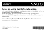
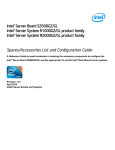
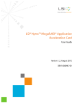
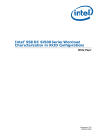
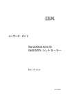
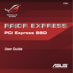
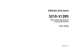
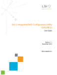
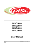
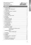
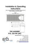
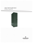
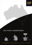
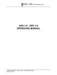
Intel® RAID SSD Cache Controller
RCS25ZB040/RCS25ZB040LX User
Guide
Intel Order Number: G78573-002
DISCLAIMER
IINFORMATION IN THIS DOCUMENT IS PROVIDED IN CONNECTION WITH INTEL PRODUCTS.
NO LICENSE, EXPRESS OR IMPLIED, BY ESTOPPEL OR OTHERWISE, TO ANY
INTELLECTUAL PROPERTY RIGHTS IS GRANTED BY THIS DOCUMENT. EXCEPT AS
PROVIDED IN INTEL'S TERMS AND CONDITIONS OF SALE FOR SUCH PRODUCTS, INTEL
ASSUMES NO LIABILITY WHATSOEVER AND INTEL DISCLAIMS ANY EXPRESS OR IMPLIED
WARRANTY, RELATING TO SALE AND/OR USE OF INTEL PRODUCTS INCLUDING LIABILITY
OR WARRANTIES RELATING TO FITNESS FOR A PARTICULAR PURPOSE,
MERCHANTABILITY, OR INFRINGEMENT OF ANY PATENT, COPYRIGHT OR OTHER
INTELLECTUAL PROPERTY RIGHT.
A "Mission Critical Application" is any application in which failure of the Intel Product could result,
directly or indirectly, in personal injury or death. SHOULD YOU PURCHASE OR USE INTEL'S
PRODUCTS FOR ANY SUCH MISSION CRITICAL APPLICATION, YOU SHALL INDEMNIFY AND
HOLD INTEL AND ITS SUBSIDIARIES, SUBCONTRACTORS AND AFFILIATES, AND THE
DIRECTORS, OFFICERS, AND EMPLOYEES OF EACH, HARMLESS AGAINST ALL CLAIMS
COSTS, DAMAGES, AND EXPENSES AND REASONABLE ATTORNEYS' FEES ARISING OUT
OF, DIRECTLY OR INDIRECTLY, ANY CLAIM OF PRODUCT LIABILITY, PERSONAL INJURY, OR
DEATH ARISING IN ANY WAY OUT OF SUCH MISSION CRITICAL APPLICATION, WHETHER
OR NOT INTEL OR ITS SUBCONTRACTOR WAS NEGLIGENT IN THE DESIGN,
MANUFACTURE, OR WARNING OF THE INTEL PRODUCT OR ANY OF ITS PARTS.
Intel may make changes to specifications and product descriptions at any time, without notice.
Designers must not rely on the absence or characteristics of any features or instructions marked
"reserved" or "undefined". Intel reserves these for future definition and shall have no responsibility
whatsoever for conflicts or incompatibilities arising from future changes to them. The information
here is subject to change without notice. Do not finalize a design with this information.
The products described in this document may contain design defects or errors known as errata
which may cause the product to deviate from published specifications. Current characterized errata
are available on request.
Copies of documents which have an order number and are referenced in this document, or other
Intel literature, may be obtained by calling 1-800-548-4725, or go to:
http://www.intel.com/design/literature.htm.
ii
Intel® RAID SSD Cache Controller RCS25ZB040/RCS25ZB040LX User Guide
Preface
This is the primary user guide for the Intel® RAID SSD Cache Controller
RCS25ZB040/RCS25ZB040LX. It contains installation instructions and specifications.
Audience
The people who benefit from this document are:
• Engineers who are designing an Intel® RAID Controller.
• Anyone installing an Intel® RAID Controller.
Organization
This document includes the following chapters and appendices:
• Chapter 1 provides a general overview of the Intel® RAID SSD Cache Controller
RCS25ZB040/RCS25ZB040LX.
• Chapter 2 describes the procedures for installing the Intel® RAID SSD Cache
Controller RCS25ZB040/RCS25ZB040LX hardware.
• Chapter 3 describes the characteristics and technical specifications of the Intel®
RAID SSD Cache Controller RCS25ZB040/RCS25ZB040LX.
Related Publication
This is the primary hardware guide for the Intel® RAID SSD Cache Controller
RCS25ZB040/RCS25ZB040LX family of controllers. It contains installation instructions
and specifications to aid in the configuration and use of this product.
Intel® RAID SSD Cache Controller RCS25ZB040/RCS25ZB040LX User Guide
iii
iv
Intel® RAID SSD Cache Controller RCS25ZB040/RCS25ZB040LX User Guide
Table of Contents
Preface ........................................................................................................................ iii
Audience ............................................................................................................................... iii
Organization ......................................................................................................................... iii
Related Publication ............................................................................................................... iii
Overview of Intel® RAID SSD Cache Controller RCS25ZB040/RCS25ZB040LX ... 1
Key Features and Benefits of the Intel® RAID SSD Cache Controller
RCS25ZB040/RCS25ZB040LX ..................................................................................... 3
Configuration Scenarios ........................................................................................................ 4
Intel® RAID SSD Cache Controller RCS25ZB040/RCS25ZB040LX Hardware Installation ............................................................................................................................ 7
Requirements ........................................................................................................................ 7
Installation and Configuration Overview ................................................................................ 7
Hardware and Software Installation Overview ....................................................................... 8
Quick Installation of the Intel® RAID SSD Cache Controller RCS25ZB040/RCS25ZB040LX 9
Detailed Installation of the Intel® RAID SSD Cache Controller RCS25ZB040/RCS25ZB040LX 10
RAID Cache Protection Kit (optional) ..................................................................................13
SAS Device Cables and Connectors ...................................................................................14
After Installing the Intel® RAID SSD Cache Controller RCS25ZB040/RCS25ZB040LX Card ... 14
Intel® RAID SSD Cache Controller RCS25ZB040/RCS25ZB040LX Characteristics
17
Flash Memory Capacity .......................................................................................................17
LEDs ....................................................................................................................................17
Dirty Cache LED Header (J1) ......................................................................................18
Activity LED Header (J4) .............................................................................................18
Heartbeat LED .............................................................................................................18
Life Status LED ............................................................................................................19
LEDs on the Backside of the board .............................................................................19
Connectors ..........................................................................................................................19
RAID Cache Protection Module Connector (J3) ..........................................................19
UART Connector (J5) ..................................................................................................19
Modular RAID Key Header (J6) ...................................................................................20
SAS/SATA Connector (J7) ..........................................................................................20
Flash Module Connectors (J8 and J9) .........................................................................20
Test Header (J10) ........................................................................................................20
PCIe Connector (J11) ..................................................................................................20
Physical Characteristics ..............................................................................................20
Environmental Specifications ...............................................................................................22
Power Requirements ...................................................................................................22
Intel® RAID SSD Cache Controller RCS25ZB040/RCS25ZB040LX User Guide
v
Thermal and Atmospheric Limits ................................................................................. 22
Intel® RAID SSD Cache Controller RCS25ZB040/RCS25ZB040LX Certifications and Safety
Characteristics ............................................................................................................ 23
vi
Intel® RAID SSD Cache Controller RCS25ZB040/RCS25ZB040LX User Guide
List of Figures
Figure 1. Data Flow on a Intel® RAID SSD Cache Controller RCS25ZB040/RCS25ZB040LX 1
Figure 2. Data Flow on a Intel® RAID SSD Cache Controller RCS25ZB040/RCS25ZB040LX 5
Figure 3. TPM module Dimensioned Drawing........................................................................... 8
Figure 4. Example of an Intel® RAID SSD Cache Controller RCS25ZB040/RCS25ZB040LX
Board Installation and Cabling ................................................................................................ 10
Figure 5. Example of an Intel® RAID SSD Cache Controller RCS25ZB040/RCS25ZB040LX
Board Installation in a PCI Express* Slot ................................................................................ 12
Figure 6. RAID Cache Protection Module ............................................................................... 13
Figure 7. Internal SAS cables for Connecting SAS or SATA devices ..................................... 14
Figure 8. Intel® RAID SSD Cache Controller RCS25ZB040/RCS25ZB040LX Card Layout... 21
Intel® RAID SSD Cache Controller RCS25ZB040/RCS25ZB040LX User Guide
vii
viii
Intel® RAID SSD Cache Controller RCS25ZB040/RCS25ZB040LX User Guide
List of Tables
Table 1. Intel® RAID SSD Cache Controller RCS25ZB040/RCS25ZB040LX Board Sizes ............. 2
Table 2. Intel® RAID SSD Cache Controller RCS25ZB040/RCS25ZB040LX Board Sizes ........... 17
Table 3. Dirty Cache Header J1 ..................................................................................................... 18
Table 4. Activity LED Header (J4) .................................................................................................. 18
Table 5. Intel® RAID SSD Cache Controller RCS25ZB040/RCS25ZB040LX Card UART Pinout . 19
Table 6. Maximum Power Requirements ....................................................................................... 22
Intel® RAID SSD Cache Controller RCS25ZB040/RCS25ZB040LX User Guide
ix
x
Intel® RAID SSD Cache Controller RCS25ZB040/RCS25ZB040LX User Guide
1
Overview of Intel® RAID SSD Cache
Controller
RCS25ZB040/RCS25ZB040LX
This document is the primary reference and user’s guide for the Intel® RAID SSD Cache
Controller RCS25ZB040/RCS25ZB040LX based on the Intel® 6Gb/s SAS/SATA RAID
On-a-Chip device. This document contains complete installation instructions for the
Intel® RAID SSD Cache Controller RCS25ZB040/RCS25ZB040LX and includes the
product specifications.
The Intel® RAID SSD Cache Controller RCS25ZB040/RCS25ZB040LX is a
combination of Intel® proven MegaRAID controller technology coupled with built-in
Flash modules to be used as data cache devices with the help of Intel® SSD Cache 2.0
software. The Intel® RAID SSD Cache Controller RCS25ZB040/RCS25ZB040LX is a
direct-attached storage (DAS) device designed to accelerate application storage
performance by using intelligent caching from SSD Flash modules directly attached to the
RAID controller. The Intel® RAID SSD Cache Controller
RCS25ZB040/RCS25ZB040LX increases the storage performance up to 30x, but retains
the current investment in DAS. Using intelligent caching algorithms to help identify
application hot data, the frequently accessed data is stored and accessed from Flash,
enabling the lowest possible latency. The following figure illustrates the flow of data on
the Intel® RAID SSD Cache Controller RCS25ZB040/RCS25ZB040LX.
AF005946
Figure 1. Data Flow on a Intel® RAID SSD Cache Controller
RCS25ZB040/RCS25ZB040LX
Intel® RAID SSD Cache Controller RCS25ZB040/RCS25ZB040LX User Guide
1
Note: Convention of usage of important terms:
Nytro Cache: This term refers to the SSD Flash module used for user data cache, called
Nytro Cache.
SSD: This term refers to external SSDs.
Intel offers Intel® RAID SSD Cache Controller RCS25ZB040/RCS25ZB040LX family to
provide enterprise proven performance acceleration and data protection for direct attach
storage (DAS). The differences between the Intel® RAID SSD Cache Controller
RCS25ZB040/RCS25ZB040LX family members are the amount of Flash memory
mounted on the controller as shown in the following table:
Table 1. Intel® RAID SSD Cache Controller RCS25ZB040/RCS25ZB040LX
Board Sizes
Intel® RAID SSD Cache Controller
RCS25ZB040/RCS25ZB040LX
Flash Capacity
Intel® RAID SSD Cache Controller
RCS25ZB040
256 GB
Intel® RAID SSD Cache Controller
RCS25ZB040LX
1 TB
Note: In addition to the cache capacity listed in this document, an additional 25% is held in
reserve as “over provisioned” capacity to extend the usable life of the product.
These cards address the growing demand for increased data throughput in database
applications, cloud computing, and data centers. These controllers provide:
• A four-lane mini-SAS connector for internal disk connection to 6.0 Gb/s SAS/SATA
hard disk drives or for internal drive bay connection
• An eight-lane, PCI Express* 3.0 host interface
• Direct attached Nytro Flash modules - up to 1TB capacity (two Nytro Flash
modules)
• Flash volumes for caching
— Nytro Flash modules are automatically configured to single Nytro cache drive
by default
— Existing and new Nytro cache drives automatically assigned for caching
• Optional SuperCap connection to protect DRAM content in the event of power
failure
• Caching lightens the HDD load so that HDD RAID rebuilds complete faster and
removes traditional HDD head wear from accessing small block requests typical in
database environments
2
Intel® RAID SSD Cache Controller RCS25ZB040/RCS25ZB040LX User Guide
The Intel® RAID SSD Cache Controller RCS25ZB040/RCS25ZB040LX provides
accelerated performance and improved manageability to MegaRAID with its two
embedded Nytro Flash modules. The Intel® RAID SSD Cache Controller
RCS25ZB040/RCS25ZB040LX uses Nytro Flash memory in front of the connected hard
disk drive (HDD) volumes to create high-capacity and high-performance acceleration
cache pools.
The Intel® RAID SSD Cache Controller RCS25ZB040/RCS25ZB040LX is based on the
LSISAS2208 RAID On-a-Chip (ROC). This device is compliant with the Fusion-MPT™
architecture and provides a PCI Express* x8 interface.
The Intel® RAID SSD Cache Controller RCS25ZB040/RCS25ZB040LX provides
enterprise class data protection and transparent performance acceleration to directattached SCSI storage volumes. The card provides reliability, high performance, and faulttolerant drive subsystem management. Performance acceleration is powered by intelligent
caching using the onboard Nytro Flash module.
Note: Care should be taken to assess any decision to mix SAS drives and SATA drives within the
same virtual drive (VD). Although drives can be mixed, this practice is strongly
discouraged because the drives have different performance and reliability characteristics
and hence the SAS and SATA drives should not be mixed in the same enclosure.
Key Features and Benefits of the Intel® RAID SSD
Cache Controller RCS25ZB040/RCS25ZB040LX
•
•
•
•
Automatic self-starting and self-configuring of cache volumes
Supports both Read and Write caching
Transparent to applications, file systems, OSs, and device drivers
Provides an economical solution for accelerating applications — by storing
frequently accessed data on low latency Nytro Flash modules while existing SAS or
SATA connected hard drives to achieve a balance of performance and cost savings
• Uses Nytro Flash modules reducing compatibility issues
• Specialized server off load processors include the LSISAS2208 dual core RAID-onChip process and two LSI* SandForce® SF-2582 Nytro Flash modules
• MD2 Low profile (6.6" X 2.536")
• x8 PCI Express* 3.0 host interface
• RAID level support for Nytro Flash modules as RAID 0 or RAID 1
— RAID 1 is enabled when the user enables the write-back mode of the cache
— On initial power up, the card auto configures as Nytro Cache Drive Group 0,
RAID 1, Write Back configuration
• RAID level support for hard disk drives
— RAID levels 0, 1, 5, and 6
Intel® RAID SSD Cache Controller RCS25ZB040/RCS25ZB040LX User Guide
3
— RAID spans 10, 50, and 60
• Internal drive bay support
• JBOD mode support
• Nytro Flash module helps protect cache in the event of power fail — no battery
required
• SuperCap kit (option) to protect DRAM content in the event of power failure
• Faster rebuilds will occur due to servicing most storage requests from Nytro Flash
module
• Compatible with existing RWC2 management interfaces
• Zero administrative overhead
Configuration Scenarios
You can use the Intel® RAID SSD Cache Controller RCS25ZB040/RCS25ZB040LX in
the following scenarios:
• Internal SATA configuration: In this configuration, use the RAID card as a high-end
SATA, SATA II, or SATA III compatible card that directly-connects up to four drives
or to an internal expander. This configuration is mostly for low-end or entry servers.
Enclosure management is provided through an out-of-band I2C bus.
• Midrange internal SAS configuration: This configuration is like an internal SATA
configuration, but with high-end SAS drives. This configuration is more suitable for
low-range to midrange servers.
The following figure illustrates a direct-connect configuration. The Inter-IC (I2C)
interface communicates with peripherals. The external memory bus provides a 32-bit
memory bus, parity checking, and chip select signals for pipelined synchronous burst
static random access memory (PSBRAM), non-volatile static random access memory
(NVSRAM), and Flash ROM. The card can connect to an internal drive bay that uses an
expander.
4
Intel® RAID SSD Cache Controller RCS25ZB040/RCS25ZB040LX User Guide
32-Bit
Memory
Address/Data
Bus
SAS/SATA Device
SAS/SATA Device
SAS/SATA Device
SAS
PCI Express
RAID Controller
I2C
Interface
Flash ROM/
PSBRAM/
NVSRAM
I2C
Nytro Flash Module
SAS/SATA Device
Nytro Flash Module
8
PCI Express Interface
Figure 2. Data Flow on a Intel® RAID SSD Cache Controller
RCS25ZB040/RCS25ZB040LX
Intel® RAID SSD Cache Controller RCS25ZB040/RCS25ZB040LX User Guide
5
6
Intel® RAID SSD Cache Controller RCS25ZB040/RCS25ZB040LX User Guide
2
Intel® RAID SSD Cache Controller
RCS25ZB040/RCS25ZB040LX
Hardware Installation
Requirements
The following items are required to install a Intel® RAID SSD Cache Controller
RCS25ZB040/RCS25ZB040LX card:
• An Intel® RAID SSD Cache Controller RCS25ZB040/RCS25ZB040LX card
• A host server with an available x8 PCI Express* 3.0 slot
Note: This card also works in PCI Express* first generation slots. The PCI Express*
software is backward compatible with previous revisions of the PCI bus and
the PCI-X bus. This card will have reduced performance if you use it in the
first PCI bus.
• The Intel® RAID SSD Cache Controller RCS25ZB040/RCS25ZB040LX CDROM
drive, which contains links to the drivers and documentation
•
•
•
•
The necessary cables (not included with the product)
SAS drives or SATA drives
RAID Maintenance Free Backup Unit 3 Cache Protection Kit (Optional)
A Phillips* screwdriver
Installation and Configuration Overview
The Intel® RAID SSD Cache Controller RCS25ZB040/RCS25ZB040LX contains an
Auto Configuration utility in the onboard firmware. When the card is powered up for the
first time, the Nytro Flash modules are automatically configured as a Nytro Cache Drive
Group 0, RAID 1, write back configuration. If this configuration is what you want, the
card is ready to be used after you install the operating system drivers. If you want to
change the configuration, there are utilities included with the product to use to configure
your system. Figure 3, Installation Flowchart provides a quick overview of the different
setup configurations and utilities. This chapter of this document explains how to install the
card into your system. For software setup and configuration, see the Intel® RAID Software
User’s Guide.
Intel® RAID SSD Cache Controller RCS25ZB040/RCS25ZB040LX User Guide
7
Hardware and Software Installation Overview
The following flowchart shows the steps necessary to configure your Intel® RAID SSD
Cache Controller RCS25ZB040/RCS25ZB040LX and RAID system.
Figure 3. TPM module Dimensioned Drawing
8
Intel® RAID SSD Cache Controller RCS25ZB040/RCS25ZB040LX User Guide
Quick Installation of the Intel® RAID SSD Cache
Controller RCS25ZB040/RCS25ZB040LX
Use the following steps to install your Intel® RAID SSD Cache Controller
RCS25ZB040/RCS25ZB040LX. These steps are for experienced computer users or
installers.
1. Unpack the card and inspect it for damage. Unpack the card in a static-free
environment, and follow good antistatic grounding procedures. Remove the card
from the antistatic bag, and carefully inspect the device for damage. If you notice
any damage or if any component is missing, contact Intel® or your reseller support
person.
Caution: Back up your data before changing your system configuration.
2. Prepare the server. Turn off the power to the server, all drives, enclosures, and
server components, and disconnect the AC power cord.
3. Open the cabinet. Follow the instructions in the server technical documentation.
4. If required, replace the mounting bracket (server dependent) and install light pipe in
the Life (upper) position.
5. If required, install optional SuperCap and external LED before installing the card in
the PCIe slot.
6. Insert the Intel® RAID SSD Cache Controller RCS25ZB040/RCS25ZB040LX
card in an available PCIe slot. Locate an empty PCIe slot that offers the
maximum airflow. Remove the blank bracket panel on the server chassis that aligns
with the empty PCIe slot. Save the bracket screw, if applicable. Align the card to a
PCIe slot. Press down gently, but firmly, to correctly seat the card in the slot. The
following figure illustrates how to insert the card in a PCIe slot.
Caution: The PCIe slot must meet the 300 linear feet per minute (LFPM) minimum
airflow requirement but 500 LFPM is optimal for thermal performance.
Intel® RAID SSD Cache Controller RCS25ZB040/RCS25ZB040LX User Guide
9
Figure 4. Example of an Intel® RAID SSD Cache Controller
RCS25ZB040/RCS25ZB040LX Board Installation and Cabling
7. Secure the card to the server’s chassis. Install the bracket screw, if applicable, or
engage the server retention mechanism to secure the card to the server’s chassis.
8. Connect SAS or SATA devices to the Intel® RAID SSD Cache Controller
RCS25ZB040/RCS25ZB040LX. Make sure that the cable you use conforms to all
specifications.
9. Perform a safety check. Make sure the cables and card are installed correctly, then
close cabinet.
10. Reconnect the AC power cord to the server.
11. Turn on the power to the server. The server powers-up and auto configuration
creates a Nytro Cache Drive Group 0, RAID 1, Write Back configuration.
Intel® RAID SSD Cache Controller RCS25ZB040/RCS25ZB040LX installation is
complete.
Detailed Installation of the Intel® RAID SSD Cache
Controller RCS25ZB040/RCS25ZB040LX
This section provides detailed instructions for installing your Intel® RAID SSD Cache
Controller RCS25ZB040/RCS25ZB040LX.
1. Unpack the Intel® RAID SSD Cache Controller RCS25ZB040/RCS25ZB040LX.
Unpack and remove your Intel® RAID SSD Cache Controller
RCS25ZB040/RCS25ZB040LX. Inspect it for damage. If it appears damaged, or if
any of the following items are missing, contact your Intel® Customer and Technical
Support representative. The Intel® RAID SSD Cache Controller
RCS25ZB040/RCS25ZB040LX is shipped with the following items:
10
Intel® RAID SSD Cache Controller RCS25ZB040/RCS25ZB040LX User Guide
— A CDROM drive containing Intel® RAID SSD Cache Controller
RCS25ZB040/RCS25ZB040LX drivers for supported operating systems, RAID
configuration utilities, an electronic version of this user’s guide, and links to
other related documentation
— A license agreement
— Warranty information
2. Prepare the server. Turn off the power to the server, and disconnect the AC power
cord. Remove the server cover. Refer to the server documentation for instructions.
Before you install the card, make sure that the computer is disconnected from the
power and from any networks.
3. Open the cabinet. Follow the instructions in the server technical documentation.
4. If required, replace the mounting bracket (server dependent) and install light pipe in
the Life (upper) position.
5. If required, install optional SuperCap and external LED before installing the card in
the PCIe slot.
6. Insert the Intel® RAID SSD Cache Controller RCS25ZB040/RCS25ZB040LX
card. Locate an empty PCIe slot that offers the maximum airflow. Remove the
blank bracket panel on the server chassis that aligns with the empty PCIe slot. Save
the bracket screw, if applicable. Align the card to a PCIe slot. Press down gently,
but firmly, to correctly seat the card in the slot. Secure the bracket to the computer
chassis with the bracket screw. The following figure illustrates the installation of a
Intel® RAID SSD Cache Controller RCS25ZB040/RCS25ZB040LX in a PCI
Express* slot.
Note: Some PCIe slots support PCIe graphics cards only; if a Intel® RAID SSD
Cache Controller RCS25ZB040/RCS25ZB040LX is installed on those PCIe
slots, it will not function.
Intel® RAID SSD Cache Controller RCS25ZB040/RCS25ZB040LX User Guide
11
Caution: The PCIe slot must meet the 300 linear feet per minute (LFPM) minimum
airflow requirement but 500 LFPM is optimal for thermal performance.
Figure 5. Example of an Intel® RAID SSD Cache Controller
RCS25ZB040/RCS25ZB040LX Board Installation in a PCI Express* Slot
7. Install the SAS devices, SATA devices, or both in the host server case. Refer to
the documentation for the devices for any pre-installation configuration
requirements.
8. Connect the RAID card to the devices. Use SAS cables to connect SAS devices,
SATA devices, or both to the Intel® RAID SSD Cache Controller
RCS25ZB040/RCS25ZB040LX card. See SAS Device Cables and Connectors for
information about connecting the card to drives. System throughput problems can
occur if the SAS cables are not the correct type.
9. Turn on the power to the server. Reinstall the server cover, and reconnect the AC
power cords. Turn power on to the host server. Make sure that the power is turned
on to the SAS devices, SATA devices, or both before or at the same time that the
power is turned on to the host server. If the computer is powered up before these
devices, the devices might not be recognized. During boot, a BIOS message
appears. The firmware takes several seconds to initialize. The configuration utility
prompt times out after several seconds. The second portion of the BIOS message
shows the Intel® RAID SSD Cache Controller RCS25ZB040/RCS25ZB040LX
card number, firmware version, and cache SDRAM size. The numbering of the
cards follows the PCI slot scanning order used by the host motherboard.
10. Run the WebBIOS Configuration Utility. Run the WebBIOS Configuration
Utility to configure the drive groups and the virtual drives. When the message
Press CTRL+G for WebBIOS appears on the screen, immediately press CTRL+G
to run the utility.
11. Install the operating system driver. Intel® RAID SSD Cache Controller
RCS25ZB040/RCS25ZB040LX cards can operate under various operating
systems. To operate under these operating systems, you must install the software
12
Intel® RAID SSD Cache Controller RCS25ZB040/RCS25ZB040LX User Guide
drivers. The Intel® RAID Software User’s Guide provides information on how to
install and use the drivers. Be sure to use the latest service packs provided by the
operating system manufacturer and to review the readme file that accompanies the
driver.
RAID Cache Protection Kit (optional)
The RAID Maintenance Free Backup Unit 3 contains a RAID Cache Protection module
and a mounding bracket. The RAID Cache Protection module contains a super-capacitor
that supplies enough power to offload the DRAM cache data in the event of a power
failure. Below is a picture of the RAID Cache Protection module that plugs into the Intel®
RAID SSD Cache Controller RCS25ZB040/RCS25ZB040LX card at connector J3. For
details on the location of J3 connector, see Figure 8. The AXXRMFBU3 kit contains
cables and components not intended for use with this product, and can be discarded.
Figure 6. RAID Cache Protection Module
Intel® RAID SSD Cache Controller RCS25ZB040/RCS25ZB040LX User Guide
13
SAS Device Cables and Connectors
The figure below illustrates the cable necessary for connecting SAS or SATA drives to the
Intel® RAID SSD Cache Controller RCS25ZB040/RCS25ZB040LX card. Also the cable
necessary to connect the Intel® RAID SSD Cache Controller
RCS25ZB040/RCS25ZB040LX card to an internal drive bay.
Figure 7. Internal SAS cables for Connecting SAS or SATA devices
After Installing the Intel® RAID SSD Cache Controller
RCS25ZB040/RCS25ZB040LX Card
After you install the Intel® RAID SSD Cache Controller RCS25ZB040/RCS25ZB040LX
card and power up your system, firmware on the controller automatically configures the
controller for caching. You can view the configuration and change the configuration using
firmware on the controller.
1. For your operating system to communicate with your Intel® RAID SSD Cache
Controller RCS25ZB040/RCS25ZB040LX card, you need to install a driver that
matches your OS. The drivers perform these functions:
2. They support the PCI Express* protocol.
3. They support multiple RAID storage adapters.
4. They provide the ability to see newly configured logical drives in the configuration
software utility without rebooting the system.
14
Intel® RAID SSD Cache Controller RCS25ZB040/RCS25ZB040LX User Guide
5. They permit the random deletion of logical drives that were created by using Intel®
RAID Web Console 2 (refer to the Intel® RAID Software User’s Guide for more
information).
6. They support the use of the remaining array capacity by Intel® RAID Web Console
2.
The Intel® RAID Software User’s Guide provides detailed installation instructions for
operating system drivers. The Intel® RAID Software User’s Guide instructs you on the
configuration options and how to set them on your Intel® RAID SSD Cache Controller
RCS25ZB040/RCS25ZB040LX card.
Intel® RAID SSD Cache Controller RCS25ZB040/RCS25ZB040LX User Guide
15
16
Intel® RAID SSD Cache Controller RCS25ZB040/RCS25ZB040LX User Guide
Intel® RAID SSD Cache Controller
RCS25ZB040/RCS25ZB040LX
Characteristics
3
All of the Intel® RAID SSD Cache Controller RCS25ZB040/RCS25ZB040LX cards
contain the same connectors and headers. Therefore, there is only one board illustration
and description given in this chapter.
Flash Memory Capacity
The differences between the Intel® RAID SSD Cache Controller
RCS25ZB040/RCS25ZB040LX family of controllers are the amount of flash memory as
shown in the following table:
Table 2. Intel® RAID SSD Cache Controller RCS25ZB040/RCS25ZB040LX
Board Sizes
Intel® RAID SSD Cache Controller
RCS25ZB040/RCS25ZB040LX
Flash Capacity
Intel® RAID SSD Cache Controller
RCS25ZB040
256 GB
Intel® RAID SSD Cache Controller
RCS25ZB040LX
1 TB
Note: In addition to the cache capacity listed in this document, an additional 25% is held in
reserve as “over provisioned” capacity to extend the usable life of the product
LEDs
The Intel® RAID SSD Cache Controller RCS25ZB040/RCS25ZB040LX card contains
two surface mounted LEDs and two headers for LEDs.
Intel® RAID SSD Cache Controller RCS25ZB040/RCS25ZB040LX User Guide
17
Dirty Cache LED Header (J1)
J1 is an optional two-pin header for connecting an LED to indicate a write command is
pending. This LED is known as the Write Pending LED. Use this LED with the write-back
cache feature. The dirty cache signal is driven by GPIO(5) of the LSISAS2208. The table
below shows how to connect an LED to the J1 header.
Table 3. Dirty Cache Header J1
Pin #
Name
Description
1
DIRTY_PU
Anode of LED
2
DIRTY
Cathode of LED
Illustration of how to connect the LED
Activity LED Header (J4)
J4 is a two-pin header for connecting an LED to indicate drive activity. This activity signal
is a logical combination of the GPIO(16) and GPIO(20) pins on the LSISAS2208 device.
Activity on either port causes the activity LED to turn on. The table below shows how to
connect an LED to the J4 header.
Table 4. Activity LED Header (J4)
Pin #
Name
Description
1
D_ACTIVE_PU
Anode of LED
2
D_ACTIVE
Cathode of LED
Illustration of how to connect the LED
Heartbeat LED
The CR3 LED is mounted on the surface of the controller board. This LED is Green in
color and it indicates the LSISAS2208 device is alive. See Figure 8 for the location of the
CR3 LED.
18
Intel® RAID SSD Cache Controller RCS25ZB040/RCS25ZB040LX User Guide
Life Status LED
The CR2 LED is mounted on the surface of the controller board. This LED is bicolor RED
or GREEN and it indicates the life status of the Nytro Flash modules. See Figure 8 for the
location of the CR2 LED.
LEDs on the Backside of the board
CRB1 Orange LED = fault LED
CRB2 Blue LED = Status LED (whether off-loading or not)
CRB3 Green LED = power
Connectors
This section describes the connectors and headers on the Intel® RAID SSD Cache
Controller RCS25ZB040/RCS25ZB040LX card.
RAID Cache Protection Module Connector (J3)
J3 is for the connection for the RAID Cache Protection module. The module comes in the
optional RAID Maintenance Free Backup Unit 3. The kit comes complete including a
mounting bracket. The purpose of the RAID Cache Protection module is to protect
DRAM content on power failure.
UART Connector (J5)
The UART connector debug port requires a special cable and Intel® support to gather
detailed Input/Output Controller (IOC) status.
Table 5. Intel® RAID SSD Cache Controller RCS25ZB040/RCS25ZB040LX
Card UART Pinout
Pin #
Function
1
UART0_TX
2
Ground
3
UART0_RX
4
3.3 V
Intel® RAID SSD Cache Controller RCS25ZB040/RCS25ZB040LX User Guide
19
Modular RAID Key Header (J6)
J6 is a two-pin header that provides for connecting a modular RAID Key board for
upgrades. At this time, there are no upgrade options available.
SAS/SATA Connector (J7)
The Intel® RAID SSD Cache Controller RCS25ZB040/RCS25ZB040LX supports 6Gb/s
SAS/SATA connections through connector J7. SATA or SAS device are connected
directly to the card or through an expander. The cards contain one mini-SAS 4i connectors
(SFF-8087) that contains four SAS ports.
Flash Module Connectors (J8 and J9)
Connectors J8 and J9 are used to connect the Nytro Flash modules to the Intel® RAID
SSD Cache Controller RCS25ZB040/RCS25ZB040LX card.
Test Header (J10)
This header is reserved for testing purposes.
PCIe Connector (J11)
The Intel® RAID SSD Cache Controller RCS25ZB040/RCS25ZB040LX card supports a
x8 PCIe interface. The PCIe host interface connection is through the edge connector, J11,
which provides connections on both the top (J11B) and bottom (J11A) of the board. The
signal definitions and pin numbers conform to the PCIe Specification.
Physical Characteristics
The Intel® RAID SSD Cache Controller RCS25ZB040/RCS25ZB040LX cards are 6.6-in.
× 2.7-in. and are low-profile boards. The component height on the top and bottom of the
cards are in accordances with the PCIe Specification.
20
Intel® RAID SSD Cache Controller RCS25ZB040/RCS25ZB040LX User Guide
AF005954
Figure 8. Intel® RAID SSD Cache Controller RCS25ZB040/RCS25ZB040LX
Card Layout
Board LEDs
• Front side of card
— CR2 - Bicolor RED/GREEN LED that indicates the status and life (STS/LFE)
of the Nytro Flash modules.
— CR3 - Green LED that indicates the heartbeat (HB) of the LSISAS2208 device.
• Back side of card
— CRB1 - Orange LED that indicates a fault
— CRB2 - Blue LED that indicates a status (whether off-loading or not)
— CBR3 - Green LED that indicates power is on
Connectors and Headers
• J1 - Dirty Cache LED Header
• J2 - Test Header
• J3 - SuperCap (S-CAP) Module Connector (optional kit: RAID Maintenance Free
Backup Unit 3)
Intel® RAID SSD Cache Controller RCS25ZB040/RCS25ZB040LX User Guide
21
• J4 - Activity (ACT) Header
• J5 - Serial UART0
• J6 - Modular RAID key header (there is no hardware key)
•
•
•
•
•
J7 - Mini-SAS 4i connector (SFF-8087)
J8 - Nytro Flash module connector
J9 - Nytro Flash module connector
J10 - Test Header
J11 - Host PCIe interface connector
Environmental Specifications
Power Requirements
The following table lists the maximum power requirements for the Intel® RAID SSD
Cache Controller RCS25ZB040/RCS25ZB040LX cards under normal operation:
Table 6. Maximum Power Requirements
Card Model
Nominal Power
Operating Range
Intel® RAID Controller RCS25ZB040
less than 25 W
0°C to 45°C
Intel® RAID Controller RCS25ZB040LX
less than 25 W
0°C to 45°C
Thermal and Atmospheric Limits
The atmospheric limits for the Intel® RAID SSD Cache Controller
RCS25ZB040/RCS25ZB040LX cards are as follows:
• Temperature range: 0°C to 45°C (32°F to 113°F) (dry bulb)
• Relative humidity range:
— Non-operating - 20% to 95%
— Operating - 20% to 80%
• Maximum dew point temperature: 32°C (89.6°F)
• Minimum airflow: 300 linear feet per minute
The following limits define the storage and transit environment for the Intel® RAID SSD
Cache Controller RCS25ZB040/RCS25ZB040LX cards:
• Temperature range: -45°C to +105°C (–49°F to +221°F) (dry bulb)
22
Intel® RAID SSD Cache Controller RCS25ZB040/RCS25ZB040LX User Guide
• Relative humidity range: 5 percent to 90 percent noncondensing
Intel® RAID SSD Cache Controller
RCS25ZB040/RCS25ZB040LX Certifications and
Safety Characteristics
All Intel® RAID SSD Cache Controller RCS25ZB040/RCS25ZB040LX cards meet or
exceed the requirements of UL flammability rating 94V-0. Each bare board is marked
with the supplier’s name or trademark, type, and UL flammability rating. Because these
boards are installed in a PCIe bus slot, all voltages are less than the SELV 42.4-V limit.
The design and implementation of the Intel® RAID SSD Cache Controller
RCS25ZB040/RCS25ZB040LX cards minimizes electromagnetic emissions,
susceptibility to radio frequency energy, and the effects of electrostatic discharge.
The Intel® RAID SSD Cache Controller RCS25ZB040/RCS25ZB040LX cards meet the
following integrated electromagnetic interference (EMI) compliance labels:
•
•
•
•
•
•
•
Europe: CE mark
Australia: C-Tick mark
Canadian Compliance Statement: ICES
United States: FCC Class B, marked with the FCC Self-Certification logo
Japan: VCCI
Korean: KCC
Taiwan: BSMI
The Intel® RAID SSD Cache Controller RCS25ZB040/RCS25ZB040LX cards meet the
following environmental directives:
• RoHS
• WEEE
The hardware complies with the following safety specifications:
• UL Listed I.T.E. Accessory (USA and ULc (Canada)) Certification
• CB Certification – Certificate includes all National Differences and shows that the
product also complies with EN 60950-1 second edition as well as EN 60950-1 first
edition with all amendments.
Intel® RAID SSD Cache Controller RCS25ZB040/RCS25ZB040LX User Guide
23
24
Intel® RAID SSD Cache Controller RCS25ZB040/RCS25ZB040LX User Guide