1
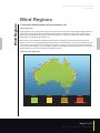
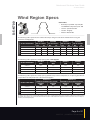
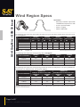
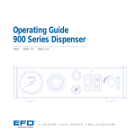
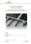
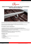
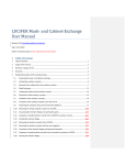
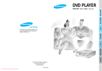
User Guide Australia Edition
AUG7-13
S-5! Attachment Solutions
Metal Roof Innovations, LTD.
www.S-5au.com
+1-719-825-3432
Table of Contents
Welcome
1
Responsibility
2
Wind Regions
3
Installation Planning
4
Wind Region Specs
5
Clamp Orientation
14
Bracket Orientation
20
S-5!® Photovoltiac Attachment System
24
PV Rail Attachment
26
Rooftop PV Installation
27
Installation Tools
27
Clamp Installation
27
Bracket Installation
32
PV Installation
34
Disclaimer
37
Table of Contents
AUG7-13 | AS/NZS1170 Standards
Attachment Solutions User Guide
Australia Edition
Introduction
Welcome
S-5!® Australian Code Compliant Planning and Installation in accordances with AS/
NZS1170
S-5! patented hardware technology makes these attachments quick, simple, secure, and as dependable as
the roof systems they complement.
Please review this manual thoroughly before installing an S-5! clamp or bracket with either the S-5-PV Kit
or a third party solar mounting application system. This manual provides (1) supporting documentation
for building permit applications relating to the range of S-5! clamps used with a third party mounting
system, (2) installation conditions, and (3) planning and installation instructions for use of S-5! products.
S-5! products, when installed in accordance with this guide, will be structurally adequate in accordance
with AS/NZS1170 standards. During installation, and especially when working on the roof, be sure to
observe the appropriate safety regulations, and please pay attention to the relevant regulations of your
local region. Any loads imposed on the S-5! clamp will be transferred to the roof sheets. Roof sheets must
be adequately attached to building structure to resist these loads. The user and/or the installer of these
parts are responsible for all necessary engineering and design for the intended use of these parts in an
assembly or application.
Please check that you are using the current version of the installation manual by contacting MAK Fastener
Specialists Pty Ltd, via email at [email protected]
MAK Fasteners: +61 (0)8 7481 6111
Page 1 of 37
AUG7-13 | AS/NZS1170 Standards
Responsibility
Responsibility
The installer is solely responsible for:
• Complying with all applicable local or national building codes, including any that may supersede this
manual.
• Ensuring that S-5!® and other products are appropriate for the particular installation and the installation
environment.
• Ensuring that the roof, its structural frame, connections, and other structural support members can
support the array under all relevant loading conditions (this total assembly is hereafter referred to as the
roof framing assembly).
• Ensuring safe installation of all electrical aspects of the PV array.
Loads imposed on the S-5! clamps and brackets will be transferred to the roof sheeting and roof sheeting
fixings. Roof sheeting, roof sheeting fixings, and roof supporting structure must have sufficient strength
to carry all applicable loads. The makers of S-5! clamps and brackets make no representations with respect
to these variables. It is the responsibility of the user to verify this information, or seek assistance from a
qualified design professional, if necessary.
The manufacturer expresses no opinions as to the suitability of the S-5!
clamp or bracket for any specific application or project condition.
ALWAYS PROVIDE WORKER FALL PROTECTION WHEN INSTALLING S-5!. S-5! DOES NOT APPROVE PRODUCTS
FOR USE IN PERSONAL FALL RESTRAINT/FALL PROTECTION APPLICATIONS. S-5! PRODUCTS MAY BE USED
AS A COMPONENT IN A FALL PROTECTION SYSTEM ONLY WHEN THE SYSTEM MANUFACTURER PROVIDES
APPROPRIATE APPROVALS!
Before proceeding, note the following:
• This document addresses only wind loads on the assumption that wind produces the maximum load
factor affecting an installation. Verify that other local factors, such as snow loads and earthquake
effects, do not exceed the wind loads; precedence shall be given to any factor that does. Wind loads are
considered to act on the entire projected area, or may be perpendicular to any surface.
• For critical installations, inquire for specific test data of ultimate tensile load on specific panel materials
and seam types. When tabled values are used, fastener tensions should be verified and factors of safety
should be used as appropriate.
Code-Compliant Planning:
This document is designed to assist with installations utilizing S-5! clamps in conjunction with third party
product applications in accordance with AS/NZS1170.
Page 2 of 37
AUG7-13 | AS/NZS1170 Standards
Attachment Solutions User Guide
Australia Edition
Wind Regions
Wind Regions
1. Determine the Wind Region of Your Installation Site
Region Definition:
Wind Regions are pre-defined for all of Australia by Australian Standard 1170. The Wind Region does not
reflect surrounding topography or buildings. Wind speeds are defined for each region and the design
wind speeds are based on the region wind speed, modified as necessary to reflect the effects of local
topography, shielding, building height, etc.
Much of Australia is designated Region A which indicates a Regional Ultimate Basic Wind Velocity of
45msec. Some areas are designated Region B (57msec). Local authorities will advise if this applies in your
area. Region C areas (69msec) are generally referred to as cyclonic and are generally limited to northern
coastal areas. Most Region C zones end 50km - 100km inland. Region D (88msec) Australia’s worst Cyclonic
Region between Carnarvon and Pardoo in Western Australia.
Australian wind region map:
Darwin
Cairns
Broome
Port Hedlund
20
o
25
o
27
o
30
o
20
o
25
o
27
o
30
o
Carnarvon
Brisbane
Perth
Adelaide
Albany
Canberra
Sydney
Melbourne
Hobart
RegiON A
RegiON B
RegiON C
NORMAL
iNTeRMeDiATe
TROPiCAL CYCLONeS
RegiON D
SeVeRe TROPiCAL CYCLONeS
Page 3 of 37
AUG7-13 | AS/NZS1170 Standards
Planning
Installation Planning
2. Installation Conditions
• Wind loads to AS1170.2:2011
• Wind average recurrence interval of 500 years
• Wind terrain Category 2
• Shielding and topography multipliers, equal to 1.0
• Racks mounted on roofs of enclosed buildings of nominal rectangular shape
• Roof cladding: suitable for most types of metal concealed fix roof
• Roof slopes from 0° up to 60° from horizontal
• Maximum solar panel area of 1.5 m2
• Minimum of 4 clamps supporting each panel (S-5-PV Kit Installations)
• Maximum solar panel weight of 22kg/m2
• Roof structure to be checked and certified as suitable for applied rack loads prior to installation
• Solar panels to be certified by manufacturer as able to resist wind loads in accordance with
AS1170.2:2011
3. Planning and Installation Instructions for Use of S-5!® Clamps and Brackets
Determine the height of your installation site.
This document provides sufficient information for PV assembly installation height less than 20 meters.
If your installation site is more than 20 meters in height, please obtain engineering approval, and
engineering data to support your installation.
When the installation site is more than 10 meters in height and in Region C utilizing any form of a tilted
system, further engineering approval is necessary to support this type of installation.
If roofing profile is not listed within this guide, please consult S-5! for clamp suitability.
The following tables assume that determination has been made that the PV modules, PV railing and the roof
itself to which the S-5! clamps will be attached is structurally adequate. The makers of S-5! clamps make no
representations with respect to these variables. It is the responsibility of the user to verify this information, or
seek assistance from a qualified design professional, if necessary.
Page 4 of 37
AUG7-13 | AS/NZS1170 Standards
Attachment Solutions User Guide
Australia Edition
Wind Region Specs
S-5-K 700
Roof Profiles:
• BlueScope / LYSAGHT - Klip-lok 700
HI-STRENGTH®/ Klip-lock Classic® 700
• Stramit - Speed Deck Ultra®
• Fielders - KingKlip®
• Metroll - Metlok 700®
The following table represents the number of clamps along one side of the module frame using the
S-5-PV Kit and EdgeGrab™
Installation Height
Region A
(No. of Clamps)
Region B
(No. of Clamps)
Region C
(No. of Clamps)
Region D
(No. of Clamps)
MG
EG
MG
EG
MG
EG
MG
EG
5 Meters
2
2
3
2
6
3
**
**
10 Meters
2
2
3
2
8
4
**
**
15 Meters
2
2
3
2
8
4
**
**
20 Meters
2
2
3
2
**
**
**
**
S-5-PV Kit = MG
EdgeGrab = EG
**Please inquire for load test reports
The following table represents clamp spacing with a rail support.
Installation Height
Region A
(mm)
Region B
(mm)
Region C
(mm)
Region D
(mm)
5 Meters
1400
900
350
250
10 Meters
1200
800
300
210
15 Meters
1000
730
250
180
20 Meters
1000
700
250
180
The following table represents clamp spacing (module tilt parallel to roof pitch) or rail spacing (module tilt
perpendicular to roof pitch) with a 30° tilted rail support.
Installation Height
Module Tilt
Parallel to roof pitch (Clamp)
Module Tilt
perpendicular to roof pitch (Rail)
Region A
(mm)
Region B
(mm)
Region A
(mm)
Region B
(mm)
5 Meters
1210
810
1550
990
10 Meters
1000
670
1280
840
15 Meters
910
610
1170
770
20 Meters
860
570
1100
730
The figures above are based on attaching PV modules that are 1.5m weighing 22kg. These figures should be sufficient for installing smaller
PV modules. These figures also assume that determination has been made that the PV support rail, which is attached to the S-5!® clamps or
brackets, is structurally adequate.
2
Page 5 of 37
AUG7-13 | AS/NZS1170 Standards
S-5-K Grip Mini – GXM 50 Insert
Wind Region Specs
Roof Profiles:
• BlueScope / LYSAGHT - Klip-lok 700
HI-STRENGTH®/ Klip-lok Classic® 700
• Stramit - Speed Deck Ultra®
• Fielders - KingKlip®
• Metroll - Metlok 700®
The following table represents the number of clamps along one side of the module frame using the S-5-PV
Kit and EdgeGrab™
Installation Height
Region A
(No. of Clamps)
Region B
(No. of Clamps)
Region C
(No. of Clamps)
Region D
(No. of Clamps)
MG
EG
MG
EG
MG
EG
MG
EG
5 Meters
3
2
4
2
6
3
**
**
10 Meters
3
2
5
3
7
4
**
**
15 Meters
3
2
5
3
7
4
**
**
20 Meters
4
2
6
3
8
4
**
**
S-5-PV Kit = MG
EdgeGrab = EG **Please inquire for load test reports
The following table represents clamp spacing with a rail support.
Installation Height
Region A
(mm)
Region B
(mm)
Region C
(mm)
Region D
(mm)
5 Meters
800
500
400
270
10 Meters
700
450
350
238
15 Meters
600
420
300
204
20 Meters
600
400
300
204
The following table represents clamp spacing (module tilt parallel to roof pitch) or rail spacing (module tilt
perpendicular to roof pitch) with a 30° tilted rail support.
Installation Height
Module Tilt
Parallel to roof pitch (clamp)
Region A
(mm)
Module Tilt
perpendicular to roof pitch (Rail)
Region B
(mm)
Region A
(mm)
Region B
(mm)
5 Meters
700
460
900
600
10 Meters
580
380
750
500
15 Meters
530
350
680
450
20 Meters
500
330
640
420
The figures above are based on attaching PV modules that are 1.5m2 weighing 22kg. These figures should be sufficient for installing smaller
PV modules. These figures also assume that determination has been made that the PV support rail, which is attached to the S-5!® clamps or
brackets, is structurally adequate.
Page 6 of 37
AUG7-13 | AS/NZS1170 Standards
Attachment Solutions User Guide
S-5-K Grip Mini – GXM 10 Insert
Australia Edition
Roof Profiles:
• BlueScope / LYSAGHT - Klip-lok® 406
The following table represents the number of clamps along one side of the module frame using the S-5-PV
Kit and EdgeGrab™
Installation Height
Region A
(No. of Clamps)
Region B
(No. of Clamps)
Region C
(No. of Clamps)
Region D
(No. of Clamps)
MG
EG
MG
EG
MG
EG
MG
EG
5 Meters
2
2
3
2
4
2
6
3
10 Meters
2
2
3
2
5
3
8
4
15 Meters
2
2
4
2
6
3
9
5
20 Meters
3
2
4
2
6
3
**
**
S-5-PV Kit = MG
EdgeGrab = EG **Please inquire for load test reports
The following table represents clamp spacing with a rail support.
Installation Height
Region A
(mm)
Region B
(mm)
Region C
(mm)
Region D
(mm)
5 Meters
1300
860
570
400
10 Meters
1080
700
470
330
15 Meters
980
640
430
300
20 Meters
920
610
400
280
The following table represents clamp spacing (module tilt parallel to roof pitch) or rail spacing (module tilt
perpendicular to roof pitch) with a 30° tilted rail support.
Installation Height
Module Tilt
Parallel to roof pitch (Clamp)
Module Tilt
perpendicular to roof pitch (Rail)
Region A
(mm)
Region B
(mm)
Region A
(mm)
Region B
(mm)
5 Meters
1100
720
1440
930
10 Meters
900
590
1170
760
15 Meters
820
540
1060
700
20 Meters
770
510
990
660
The figures above are based on attaching PV modules that are 1.5m2 weighing 22kg. These figures should be sufficient for installing smaller
PV modules. These figures also assume that determination has been made that the PV support rail, which is attached to the S-5!® clamps or
brackets, is structurally adequate.
Page 7 of 37
AUG7-13 | AS/NZS1170 Standards
Wind Region Specs
S-5-S Mini
0.7 BMT Roof Profiles:
• BlueScope / LYSAGHT - LONGLINE
305®
• Stramit - Snaptite®
• Fielders - SNAPLOK
The following table represents the number of clamps along one side of the module frame using the S-5-PV
Kit and EdgeGrab™
Installation Height
Region A
(No. of Clamps)
S-5-PV Kit
Region A
(No. of Clamps)
EdgeGrab™
Region B
(No. of Clamps)
S-5-PV Kit
Region B
(No. of Clamps)
EdgeGrab™
5 Meters
2
2
2
2
10 Meters
2
2
2
2
15 Meters
2
2
2
2
20 Meters
2
2
2
2
The following table represents clamp spacing with a rail support.
Installation Height
Region A
(mm)
Region B
(mm)
Region C
(mm)
Region D
(mm)
5 Meters
2500
1800
N/A
N/A
10 Meters
2100
1500
N/A
N/A
15 Meters
1900
1300
N/A
N/A
20 Meters
1800
1200
N/A
N/A
The following table represents clamp spacing (module tilt parallel to roof pitch) or rail spacing (module tilt
perpendicular to roof pitch) with a 30° tilted rail support.
Installation Height
Module Tilt
Parallel to roof pitch (clamp)
Module Tilt
perpendicular to roof pitch (Rail)
Region A
(mm)
Region B
(mm)
Region A
(mm)
Region B
(mm)
5 Meters
2100
1500
3000
2000
10 Meters
1750
1250
2450
1600
15 Meters
1600
1150
2250
1500
20 Meters
1500
1080
2100
1300
The figures above are based on attaching PV modules that are 1.5m2 weighing 22kg. These figures should be sufficient for installing smaller
PV modules. These figures also assume that determination has been made that the PV support rail, which is attached to the S-5!® clamps or
brackets, is structurally adequate.
Page 8 of 37
AUG7-13 | AS/NZS1170 Standards
Attachment Solutions User Guide
TopFix CorruBracket-AU™ – 0.7 BMT
Australia Edition
0.7 BMT Roof Profiles:
• Corrugated Roof
The following table represents the number of clamps along one side of the module frame using the S-5-PV
Kit and EdgeGrab™
Installation Height
Region A
(No. of Clamps)
S-5-PV Kit
Region A
(No. of Clamps)
EdgeGrab™
Region B
(No. of Clamps)
S-5-PV Kit
Region B
(No. of Clamps)
EdgeGrab™
5 Meters
2
2
2
2
10 Meters
2
2
2
2
15 Meters
2
2
2
2
20 Meters
2
2
2
2
The following table represents clamp spacing with a rail support.
Installation Height
Region A
(mm)
Region B
(mm)
Region C
(mm)
Region D
(mm)
5 Meters
1800
1200
N/A
N/A
10 Meters
1500
1000
N/A
N/A
15 Meters
1400
900
N/A
N/A
20 Meters
1300
800
N/A
N/A
The following table represents clamp spacing (module tilt parallel to roof pitch) or rail spacing
(module tilt perpendicular to roof pitch) with a 30° tilted rail support.
Installation Height
Module Tilt
Parallel to roof pitch (Clamp)
Module Tilt
perpendicular to roof pitch (Rail)
Region A
(mm)
Region B
(mm)
Region A
(mm)
Region B
(mm)
5 Meters
1500
1050
2100
1400
10 Meters
1300
900
1850
1100
15 Meters
1200
800
1500
1000
20 Meters
1050
675
1200
850
The figures above are based on attaching PV modules that are 1.5m2 weighing 22kg. These figures should be sufficient for installing smaller
PV modules. These figures also assume that determination has been made that the PV support rail, which is attached to the S-5!® clamps or
brackets, is structurally adequate.
Page 9 of 37
AUG7-13 | AS/NZS1170 Standards
TopFix CorruBracket-AU™ – 0.5 BMT
Wind Region Specs
0.5 BMT Roof Profiles:
• Corrugated Roof
The following table represents the number of clamps along one side of the module frame using the S-5-PV
Kit and EdgeGrab™
Installation Height
Region A
(No. of Clamps)
S-5-PV Kit
Region A
(No. of Clamps)
EdgeGrab™
Region B
(No. of Clamps)
S-5-PV Kit
Region B
(No. of Clamps)
EdgeGrab™
5 Meters
2
2
2
2
10 Meters
2
2
2
2
15 Meters
2
2
2
2
20 Meters
2
2
2
2
The following table represents clamp spacing with a rail support.
Installation Height
Region A
(mm)
Region B
(mm)
Region C
(mm)
Region D
(mm)
5 Meters
2100
1200
N/A
N/A
10 Meters
1800
1000
N/A
N/A
15 Meters
1600
900
N/A
N/A
20 Meters
1450
800
N/A
N/A
The following table represents clamp spacing (module tilt parallel to roof pitch) or rail spacing (module tilt
perpendicular to roof pitch) with a 30° tilted rail support.
Installation Height
Module Tilt
Parallel to roof pitch (Clamp)
Region A
(mm)
Region B
(mm)
Module Tilt
perpendicular to roof pitch (Rail)
Region A
(mm)
Region B
(mm)
5 Meters
1800
1200
2500
1600
10 Meters
1500
1000
2100
1400
15 Meters
1400
900
1900
1300
20 Meters
1300
800
1800
1200
The figures above are based on attaching PV modules that are 1.5m2 weighing 22kg. These figures should be sufficient for installing smaller
PV modules. These figures also assume that determination has been made that the PV support rail, which is attached to the S-5!® clamps or
brackets, is structurally adequate.
Page 10 of 37
AUG7-13 | AS/NZS1170 Standards
Attachment Solutions User Guide
TopFix CorruBracket-AU™ Mini – 0.5 BMT
Australia Edition
0.5 BMT Roof Profiles:
• Corrugated Roof
The following table represents the number of clamps along one side of the module frame using the S-5-PV
Kit and EdgeGrab™
Installation Height
Region A
(No. of Clamps)
S-5-PV Kit
Region A
(No. of Clamps)
EdgeGrab™
Region B
(No. of Clamps)
S-5-PV Kit
Region B
(No. of Clamps)
EdgeGrab™
5 Meters
2
2
2
2
10 Meters
2
2
2
2
15 Meters
2
2
2
2
20 Meters
2
2
2
2
The following table represents clamp spacing with a rail support.
Installation Height
Region A
(mm)
Region B
(mm)
Region C
(mm)
Region D
(mm)
5 Meters
1800
1200
N/A
N/A
10 Meters
1500
1000
N/A
N/A
15 Meters
1400
900
N/A
N/A
20 Meters
1300
800
N/A
N/A
The following table represents clamp spacing (module tilt parallel to roof pitch) or rail spacing
(module tilt perpendicular to roof pitch) with a 30° tilted rail support.
Installation Height
Module Tilt
Parallel to roof pitch (Clamp)
Module Tilt
perpendicular to roof pitch (Rail)
Region A
(mm)
Region B
(mm)
Region A
(mm)
Region B
(mm)
5 Meters
1800
1200
2500
1600
10 Meters
1500
1000
2100
1400
15 Meters
1300
900
1900
1300
20 Meters
1200
800
1800
1200
The figures above are based on attaching PV modules that are 1.5m2 weighing 22kg. These figures should be sufficient for installing smaller
PV modules. These figures also assume that determination has been made that the PV support rail, which is attached to the S-5!® clamps or
brackets, is structurally adequate.
Page 11 of 37
AUG7-13 | AS/NZS1170 Standards
TrapBracket™ – 0.7 BMT
Wind Region Specs
0.7 BMT Roof Profiles:
• Kingspan - KS1000 RW
The following table represents the number of clamps along one side of the module frame using the S-5-PV
Kit and EdgeGrab™
Installation Height
Region A
(No. of Clamps)
S-5-PV Kit
Region A
(No. of Clamps)
EdgeGrab™
Region B
(No. of Clamps)
S-5-PV Kit
Region B
(No. of Clamps)
EdgeGrab™
5 Meters
2
2
2
2
10 Meters
2
2
2
2
15 Meters
2
2
2
2
20 Meters
2
2
2
2
The following table represents clamp spacing with a rail support.
Installation Height
Region A
(mm)
Region B
(mm)
Region C
(mm)
Region D
(mm)
5 Meters
1800
1200
N/A
N/A
10 Meters
1500
1000
N/A
N/A
15 Meters
1400
900
N/A
N/A
20 Meters
1300
800
N/A
N/A
The following table represents clamp spacing (module tilt parallel to roof pitch) or rail spacing (module tilt
perpendicular to roof pitch) with a 30° tilted rail support.
Installation Height
Module Tilt
Parallel to roof pitch (Clamp)
Region A
(mm)
Region B
(mm)
Module Tilt
perpendicular to roof pitch (Rail)
Region A
(mm)
Region B
(mm)
5 Meters
1800
1200
2500
1600
10 Meters
1500
1000
2100
1400
15 Meters
1300
900
1900
1300
20 Meters
1200
800
1800
1200
The figures above are based on attaching PV modules that are 1.5m2 weighing 22kg. These figures should be sufficient for installing smaller
PV modules. These figures also assume that determination has been made that the PV support rail, which is attached to the S-5!® clamps or
brackets, is structurally adequate.
Page 12 of 37
AUG7-13 | AS/NZS1170 Standards
Attachment Solutions User Guide
TrapBracket™ – 0.5 BMT
Australia Edition
0.5 BMT Roof Profiles:
• Kingspan - KS1000 RW
The following table represents the number of clamps along one side of the module frame using the S-5PV Kit and EdgeGrab™
Installation Height
Region A
(No. of Clamps)
S-5-PV Kit
Region A
(No. of Clamps)
EdgeGrab™
Region B
(No. of Clamps)
S-5-PV Kit
Region B
(No. of Clamps)
EdgeGrab™
5 Meters
2
2
2
2
10 Meters
2
2
2
2
15 Meters
2
2
2
2
20 Meters
2
2
2
2
Region C
(mm)
Region D
(mm)
The following table represents clamp spacing with a rail support.
Installation Height
Region A
(mm)
Region B
(mm)
5 Meters
2100
1200
N/A
N/A
10 Meters
1800
1000
N/A
N/A
15 Meters
1600
900
N/A
N/A
20 Meters
1450
800
N/A
N/A
The following table represents clamp spacing (module tilt parallel to roof pitch) or rail spacing (module tilt
perpendicular to roof pitch) with a 30° tilted rail support.
Installation Height
Module Tilt
Parallel to roof pitch (Clamp)
Module Tilt
perpendicular to roof pitch (Rail)
Region A
(mm)
Region B
(mm)
Region A
(mm)
Region B
(mm)
5 Meters
1800
1200
2500
1600
10 Meters
1500
1000
2100
1400
15 Meters
1400
900
1900
1300
20 Meters
1300
800
1800
1200
The figures above are based on attaching PV modules that are 1.5m2 weighing 22kg. These figures should be sufficient for installing smaller
PV modules. These figures also assume that determination has been made that the PV support rail, which is attached to the S-5!® clamps or
brackets, is structurally adequate.
Page 13 of 37
AUG7-13 | AS/NZS1170 Standards
S-5-K700
Clamp Orientation
4. Orientation of Clamps
4.1 S-5-K700
S-5-K700 attaches to the roof sheeting rib by the tightening one M8 hex flange stainless steel bolt joining
the two portions of the clamp usually using an industrial grade screw gun. The clamp compresses the
roof panel rib material against the opposite walls of each side of the clamp. The closed clamp connection
will deform the panel rib material causing a compression fit between the clamp and the roof panel seam
material, but does not pierce metal roof paneling. Threaded holes in the clamp and the A2 stainless steel
hardware are used to attach the ancillary items to the clamps.
The S-5-K700 is furnished with two 300-series stainless steel M8 (1.25 x 16mm) hex flange bolts with
a 13mm hex head. The clamp is made of structural 6061 T6 aluminium and is compatible with most
common metal roofing materials, excluding copper.
M8 - 1.25
Hex Flange Bolt
1.42"
(36.00 mm)
1.97"
(50.00 mm)
M8 - 1.25
Hex Flange Bolt
0.98"
(25.00 mm)
2.44"
(62.00 mm)
0.98"
(25.00 mm)
1.02"
(26.00 mm)
®
1.22"
(31.00 mm)
0.87"
(22.00 mm)
Please note: All measurements are rounded
to the second decimal place.
Page 14 of 37
AUG7-13 | AS/NZS1170 Standards
Attachment Solutions User Guide
Australia Edition
S-5-K700 Profiles
Example Roof Profiles
BLUESCOPE / LYSAGHT - KLIP-LOK 700
HI-STRENGTH®
METROLL - METLOK 700®
S-5-K700 Clamp
The S-5-K700 clamp was designed with patented S-5!®
zero penetration technology for application needs with the
very distinctive roof profiles of Stramit Speed Deck Ultra®,
Lysaght Klip-Lok 700 Hi-Strength®, Fielders KingKlip® 700
and roofing types with similar profiles.
STRAMIT - SPEED DECK ULTRA®
For load critical applications such as attaching solar panels,
the assembly should be specifically engineered to each
individual project to ensure maximum hold.
See www.S-5au.com for full details.
Fielders - kingklip®
Page 15 of 37
AUG7-13 | AS/NZS1170 Standards
S-5-K Grip Mini
Clamp Orientation
4.2 S-5-K Grip™ Mini with GXM 10 or GXM 50 Insert
S-5-K Grip™ Mini clamp attaches to the roof sheeting rib by the tightening one M8 hex flange stainless
steel bolt against the clamp insert usually using an industrial grade screw gun. The insert compresses the
roof panel rib material against the opposite wall of the clamp. The insert/clamp connection will deform
the panel rib material causing a compression fit between the clamp and the roof panel seam material, but
does not pierce metal roof paneling. Threaded holes in the clamp and the A2 stainless steel hardware are
used to attach the ancillary items to the clamps.
The S-5-K Grip Mini with GXM 10 or GXM 50 insert is furnished with two 300-series stainless steel M8 (1.25
x 16mm) hex flange bolts with a 13mm hex head. The clamp is made of structural 6061 T6 aluminium and
is compatible with most common metal roofing materials, excluding copper.
S-5-K Grip Mini
with S-5-GXM 10
1.18"
(30.00 mm)
S-5-K Grip™ Mini
with S-5-GXM 50
M8-1.25x16 mm
Hex Flange Bolt
1.05"
(27.00 mm)
1.18"
(30.00 mm)
M8-1.25x16 mm
Hex Flange Bolt
1.05"
(27.00 mm)
M8-1.25 mm
Threaded Hole
1.73"
(44.00 mm)
1.73"
(44.00 mm)
0.77"
(19.00 mm)
M8-1.25 mm
Threaded
Hole
1.32"
(33.00 mm)
Please note: All
measurements
are rounded
to the second
decimal place.
M8-1.25 mm
Threaded Hole
2.15"
(55.00 mm)
Page 16 of 37
AUG7-13 | AS/NZS1170 Standards
0.77"
(19.00 mm)
M8-1.25 mm
Threaded
Hole
1.32"
(33.00 mm)
M8-1.25x16 mm
Hex Flange Bolt
2.15"
(55.00 mm)
M8-1.25x16 mm
Hex Flange Bolt
Attachment Solutions User Guide
Australia Edition
S-5-K Grip Mini Profiles
Example S-5-GXM 50 Insert Roof
Profiles
BLUESCOPE / LYSAGHT - KLIP-LOK 700
HI-STRENGTH®
METROLL - METLOK 700®
S-5-K Grip Mini Clamp
The S-5-K Grip Mini clamp was specifically developed
to fit Klip-Rib® and other bulb snap-together seams. The
design utilizes multiple inserts (sold separately) in order
to accommodate a variety of bulb snap-together profiles.
Each insert has a unique shape that allows for a tight fit and
provides increased holding strength over other attachment
options.
The S-5-K Grip mini also eliminates the large moment arm
other clamps use for these profiles. Instead, it features a
low mounting surface area, with the mounting bolt directly
over the center of the seam. This dramatically increases the
strength of the clamp, making it perfect for use with heavyduty applications.
STRAMIT - SPEED DECK ULTRA®
Fielders - kingklip®
Example S-5-GXM 10 Insert
Roof Profiles
BLUESCOPE / LYSAGHT - KLIP-LOK 406
Page 17 of 37
AUG7-13 | AS/NZS1170 Standards
S-5-S Mini
Clamp Orientation
4.3 S-5-S Mini
S-5-S Mini clamp attaches to the roof panel seam by the tightening of a round-point stainless steel
setscrew against the seam material usually using an industrial grade screw gun. The round-point stainless
steel setscrew compress the seam material causing an interlock/friction connection between the setscrew
and the roof panel seam material, but does not pierce metal roof paneling. Threaded holes in the clamp
and stainless steel hardware are used to attach the ancillary items to the clamps.
The S-5-S Mini is furnished with one 300-series stainless steel M8 (1.25 x 16mm) hex flange bolt with a
13mm hex head, and one stainless steel 3/8 (24 x .80mm) round-point setscrew. Each box includes a bit tip
for tightening setscrews using an electric screw gun. The clamp is made of structural 6061 T6 aluminium
and is compatible with most common metal roofing materials, excluding copper.
M8-1.25x16 mm bolt
1.18"
(30.00 mm)
1.50"
(38.00 mm)
M8 hole centered
on part
0.91"
(23.00 mm)
0.55"
(14.00 mm)
1.50"
(38.00 mm)
1 setscrew 3/8"-24x.80
Please note: All measurements are rounded to the second decimal place.
Page 18 of 37
AUG7-13 | AS/NZS1170 Standards
Attachment Solutions User Guide
Australia Edition
S-5-S Mini Profiles
Example Profiles
153
152
305
BLUESCOPE / LYSAGHT - LONGLINE 305®
203
203
406
fielders - SNAPLOK 406
S-5-S Mini Clamp
203
203
406
The S-5-S Mini was created specifically for popular snaptogether profiles.
The S-5-S Mini is a bit shorter than the S-5-S and has
one setscrew rather than two. The mini is the choice for
attaching all kinds of rooftop accessories: signs, walkways,
satellite dishes, antennas, rooftop lighting, lightning
protection systems, solar arrays, exhaust stack bracing,
conduit, condensate lines, mechanical equipment—just
about anything!
STRAMIT - Snaptite®
Page 19 of 37
AUG7-13 | AS/NZS1170 Standards
TopFix CorruBracket-AU™
Bracket Orientation
4.4 TopFix CorruBracket-AU™ and TopFix CorruBracket-AU™ Mini
The TopFix CorruBracket-AU attaches to the roof by driving self piercing screws (or Bulb-Tite Rivets)
through the pre-punched holes and securing directly to the sheeting; or by driving self threading screws
through the pre-punched holes into the underlying substrate using an industrial grade screw gun.
The fastener compresses the roof sheeting against the bracket and the EPDM rubber gasket creating a
compression seal for a water tight thru-fasten connection. Threaded holes in the bracket and the stainless
steel hardware are used to attach the ancillary items to the brackets.
The TopFix CorruBracket-AU and TopFix CorruBracket-AU Mini are made of structural 6061 T6 aluminium
and are compatible with most common metal roofing materials, excluding copper. Each bracket is
furnished with a factory applied EPDM rubber gasket.
TopFix CorruBracket-AU™
M8 threaded hole
0.41"
(10.41 mm)
0.78"
(19.81 mm)
3.00"
(76.20 mm)
0.84"
(21.34 mm)
0.58"
(14.73 mm)
R
3.81"
(96.77 mm)
1.58"
(40.13 mm)
A
B
3.00"
(76.20 mm)
B
A
Factory-Applied EPDM
Rubber Gaskets
A
0.49"
(12.45 mm)
B
1.01"
(25.65 mm)
TopFix CorruBracket-AU™ Mini
M8 threaded hole
0.75"
(19.81 mm)
1.18"
(29.97 mm)
R
1.58"
(40.13 mm)
0.58"
(14.73 mm)
3.81"
(96.77 mm)
0.41"
(10.41 mm)
0.84"
(21.34 mm)
3.00"
(76.20 mm)
0.59"
0.59" (14.99 mm)
(14.99 mm)
Factory-Applied EPDM
Rubber Gaskets
Please note: All measurements are rounded to the second decimal place.
Page 20 of 37
AUG7-13 | AS/NZS1170 Standards
Attachment Solutions User Guide
TopFix CorruBracket-AU™ Profiles
Australia Edition
Example Profiles
TopFix CorruBracket-AU™
TopFix CorruBracket‑AU and TopFix CorruBracket‑AU Mini are designed specifically for the Australian,
Asian, and African markets and is compatible with 16–18 mm corrugated roofing profiles. Designed to
accommodate attachment anywhere along the corrugation when attached to the sheeting only, or can
be fixed into the underlying substrate without crushing the panels corrugation. In either case, the TopFix
CorruBracket-AU leaves the valleys free of holes, further protecting against leaks!
TopFix CorruBracket‑AU comes with a factory‑applied EPDM rubber gasket seal already on the base, and
the S‑5!® patented reservoir conceals the EPDM from UV exposure, preventing UV degradation as well as
over compression of the sealant.
Page 21 of 37
AUG7-13 | AS/NZS1170 Standards
TrapBracket™
Bracket Orientation
4.5 TrapBracket™
The TrapBracket attaches to the roof by driving self piercing screws (or Bulb-Tite Rivets) through the prepunched holes and securing the bracket directly to the roof sheeting using an industrial grade screw gun.
The fastener compresses the roof sheeting against the bracket and the EPDM rubber gasket creating a
compression seal for a water tight thru-fasten connection. Threaded holes in the bracket and the stainless
steel hardware are used to attach the ancillary items to the bracket.
The TrapBracket is made of structural 6061 T6 aluminium and is compatible with most common metal
roofing materials, excluding copper. Each bracket is furnished with a factory applied EPDM rubber gasket.
Factory-Applied
EPDM Rubber Gasket
0.80"
(20.32 mm)
Use M8-1.25
(4x) 8mm thru hole
1.75"
(44.45 mm)
0.93"
(23.62 mm)
1.28"
(32.51 mm)
65º
2.21"
(56.13 mm)
0.58"
(14.73 mm)
0.39"
(9.91 mm)
3.00"
(76.20 mm)
2.11"
(53.59 mm)
Please note: All measurements are rounded to the second decimal place.
Page 22 of 37
AUG7-13 | AS/NZS1170 Standards
Attachment Solutions User Guide
Australia Edition
TrapBracket™ Profiles
TrapBracket™
TrapBracket can be used to mount
almost anything to the Kingspan® KS1000
RW profile, or other similar exposedfastened trapezoidal roof profiles. No
messy sealants to apply! No chance
for leaks! The TrapBracket comes with
a factory-applied EPDM rubber gasket
seal already on the base, and the S-5!®
patented reservoir conceals the EPDM
from UV exposure, preventing drying
and cracks.
S-5! TrapBracket is the right way to attach
almost anything to certain exposedfastened trapezoidal roof profiles;
including PV through DirectAttached™ or
Rail methods.
Example Profile
Page 23 of 37
AUG7-13 | AS/NZS1170 Standards
S-5-PV Kit
S-5!® Photovoltiac Attachment System
4.6 S-5-PV Kit
The S-5-PV Kit is furnished with the hardware shown below, excluding the attachment clamp which is
supplied separately. The S-5-PV Kit is compatible with most common metal roofing materials, including
brass. The S-5!® EdgeGrab™ and S-5-PV Kit together accommodate PV frame thicknesses 30–40 mm (if
the L-flange is positioned below the stud's hex nut) and 34–51 mm (if the L-flange is positioned above
the stud's hex nut). The embossed panel guide makes the module placement easier. The stainless steel
mounting disk with twelve nodes designed to ensure the module-to-module conductivity of anodized
aluminum module frames. This means the module is simply anchored with the kit and is automatically
bonded. No lugs or wire required except to connect one string of modules to another and to ground the
system. The mounting disk is multi-directional and rails are not required. Four strategically placed underdisk hooks assist in wire management. The PV grab ears that hold the solar panel in place are broader
to allow for ease of installation and precise module engagement. Accommodating module thickness
between 30 and 51 mm, the S-5-PV Kits fits the majority of solar panels on the market.
S-5-PV Kit
0.47"
(12.00 mm)
(UL and ETL Listed)
Listed to UL subject 2703.
ETL Listed to UL 1703.*
1.50"
(38.00 mm)
1.00"
(25.00 mm)
3.00"
(76.00 mm)
ETL Listed
Mounting Disc
0.87"
(22.00 mm)
0.71"
(18.00 mm)
Stud
Height
2.67"
(68.00 mm)
Friction Reducing
Coated Stainless Steel
Universal PV Stud w/
M8 Integral Hex Nut
Module Placement Bevel Guide
Wire Zip Tie Slots
EdgeGrab™
R
0.06"
(1.50 mm)
0.48"
(12.19 mm)
Wire
Management
Hooks
(Not UL or ETL Listed)
0.84"
(21.34 mm)
1.50"
(38.10 mm)
S-5! mini clamp not included.
Please Note:
Dimensions of both the
Universal PV Stud and
the Mounting Disk are
identical between these
two illustrations.
R
Please note: The
assembly option in the
diagram to the right
illustrates the L-flange
positioned below the
stud's hex nut.
2.00"
(50.80 mm)
S-5! mini clamp not included.
Page 24 of 37
AUG7-13 | AS/NZS1170 Standards
†
Hold Min/Max
1.18"-1.89"
(30.00-48.00 mm)
Attachment Solutions User Guide
S-5-PV Kit Hints
Australia Edition
4.6.1 Other Helpful Hints for S-5-PV Kit Applications
When Structural Capacity of Roof Panels is Unknown
The key to frequency and spacing of attachment points for PV
frames utilizing the S-5-PV Kit is to distribute loads to the metal
standing seam panels in a manner that is consistent with the
intended distribution of loads from the roof panels into the building
structure. With very few exceptions, the attachment of a single S-5!®
clamp to the seam will be stronger than a single point of attachment
of the seam to the building structure. Hence it is probable that the
“weak link” is not the S-5! clamp, but the attachment clips that hold
the metal panels to the building structure, or the beam strength of
the roof panel seam itself.
The most conservative approach to the spacing/frequency of PV
frame attachment to the roof is to determine the spacing/frequency
of the roof’s attachment to the building structure, then duplicate it at
minimum, unless the project engineer says otherwise. Determining
panel attachment spacing in one axis is very simple. Standing seam
panels’ attachment will be made using concealed hold-down clips
within the seam area of the panel. So, in that axis, the clip spacing
is the same as the seam spacing. The location of the clips along
the seam (in the other axis) can be determined by A) consultation
with the roof system manufacturer or installer, B) checking from
the underside or, C) close examination from the topside along the
seam. There will usually be a slight, but detectable, deformation of
the seam at the clip location visible from the roof’s topside. Many
standing seam roof systems are installed on “pre-engineered” steel
buildings. The attachment spacing is readily apparent by inspecting
the spacing of the structural purlins to which the panel clips are
attached from the roof underside (interior of the building).
If, for instance, the panel clips are spaced 1200mm on centre along
the seam, then use the 1200mm dimension as a maximum spacing
for the S-5! clamps (S-5! clamps may also be spaced at closer centres,
but not wider). When modules are DirectAttached™ without racking
in the landscape orientation, the smallest dimension of the PV frame
dictates the spacing dimension. Using the roof panel clip spacing
as a maximum spacing template for S-5! clamps is a sound practice,
whether the PV modules are attached directly to the S-5! clamp or to a racking system and then to the S-5!
clamp (and panel seams). To evenly distribute loads, it is also necessary that each seam be involved in the
finished assembly. thus, every time a seam is traversed, it should be attached. Such an attachment scheme
should evenly distribute wind loads into the building structure through the panels and their attachment, as
was intended in the original roof construction assembly.
These instructions are for use by those experienced in the trade. Always follow appropriate safety precautions and use appropriate tools.
Page 25 of 37
AUG7-13 | AS/NZS1170 Standards
PV Rail Attachment
PV Rail Attachment
4.7 Rail Mounted Systems
PV rails can be installed directly to the S-5!® clamp/bracket, or with use of a flanged strap or 'L' foot. The rail
should be installed perpendicular roof panel rib following the rail producer's recommended installation
practices. Support rails must have sufficient flexural strength to carry possible load conditions. Support
rails must also be adequately attached to the S-5! clamp, and the building structure must be sufficient
to carry these loads. The makers of S-5! clamps make no representations with respect to these variables.
It is the responsibility of the user to verify this information, or seek assistance from a qualified design
professional, if necessary.
4.7.1 Flush Mounted Rails
MODULES
PARALLEL TO ROOF PLANE
Rails mounted perpendicular to the roof
sheeting flush to roof slope, with modules
attached to rails parallel to the roof plane.
4.7.2 Tilt Mounted Rails
Caution: when tilting a PV array, a new and different airfoil is created, which may introduce loads for which
the roof was not engineered. These new wind dynamics result in both positive and negative point loads
that will need to be supported by the roof panels and structure.
MODULE TILT
PARALLEL TO ROOF PLANE
Rails mounted perpendicular to the roof
sheeting flush to roof slope, with modules
attached to rails tilted parallel to the roof plane.
MODULE TILT
Perpendicular TO ROOF PLANE
Rails mounted perpendicular to the roof
sheeting flush to roof slope, with modules
attached to rails tilted perpendicular to the
roof plane.
Page 26 of 37
AUG7-13 | AS/NZS1170 Standards
Attachment Solutions User Guide
Australia Edition
Rooftop PV Installation
Rooftop PV Installation
5. Determine Roof Slope
A PV system attached to the S-5!® clamp can be used for roof slopes up to 60 degrees. Please verify; the
installation site roof slope should be between 0 degrees and 60 degrees.
6. Determine Roof Installation Roof Areas
A PV system attached to the S-5! clamp, or S-5-PV Kit, should not to be installed within the high wind
pressure areas of the roof. Please reference below diagrams.
Installation Tools
7. Basic tools recommended
Basic Tools
Tape Measure
3/16 Allen Bit Tip (provided)
S-5-S Mini
String Line
Other Referenced Tools
Torque Wrench
13 mm Deep Well Socket
Screw Gun
6" Locking Pliers or Vice Grips
13 mm Spanner or Ratchet Wrench
Angle Driver
Clamp Spacing 'Jig'
(Other items may be required per field conditions.)
Page 27 of 37
AUG7-13 | AS/NZS1170 Standards
S-5-K700 Install
Clamp Installation
8. Installation Instructions
8.1 S-5-K700 Installation
When relying upon published load values, bolts should be tensioned
and verified using a calibrated torque wrench to 22 Nm.
1
Installation Instructions:
The S-5-K700 is designed to fit Klip Rib, Rib Roof, Lysaght Klip-Lok 700
Hi-Strength®, and similar seam profiles.
To Install S-5-K700:
1. Mate the clamp halves and start the M8 bolt. Thread bolt until bolt
end is just flush with the outside surface of the opposite side of the
clamp.
2
2. Place clamp assembly over the seam and force down until clamp
snaps over seam.
3. Position clamp appropriately on seam, then close clamp using
a locking C-clamp. Using a hand ratchet or electric tool (13mm),
tighten M8 bolt until clamp is closed completely.
4. Remove locking C-clamp. Consult the S-5! website at www.S-5au.
com for published data regarding holding strength.
3
4
S-5-K700
Page 28 of 37
AUG7-13 | AS/NZS1170 Standards
Attachment Solutions User Guide
S-5-S Mini Install
Australia Edition
8.2 S-5-S Mini Installation
When relying upon published load values, setscrews should
be tensioned and verified using a calibrated torque wrench
between 18 and 20 Nm when used on 8.5 mm steel and
between 15 and 17 Nm for all other metals and thinner gauges
of steel.
S-5! mini clamps are cost effective, non-penetrating standing
seam clamps designed for medium-duty applications. They are a
bit shorter than the standard clamps, having one setscrew rather
than two.
The S-5-S Mini is designed to fit snap together standing seam
profiles.
1
2
To Install S-5-S Mini:
1.
Partially thread the setscrew into the clamp by hand
2.
Determine how to position the mini clamp. On many snaptogether type seams, the setscrew is opposite the open (or
overlap) side of the seam. On other seams, this aspect of clamp
orientation is not critical.
3.
Tighten the setscrew at the base of the clamp using a screw
gun and the included screw gun bit tip. For optimal holding
strength, setscrew should be tensioned to 18 to 20 Nm [160
to 180 inch pounds] on 0.85 mm [22ga steel], and 15 to 17
Nm [130 to 150 inch pounds] on all other metals and thinner
gauges of steel.
3
Page 29 of 37
AUG7-13 | AS/NZS1170 Standards
S-5-K Grip Mini Install
Clamp Installation
8.3 S-5-K Grip Mini Installation
When relying upon published load values, bolts should be tensioned
and verified using a calibrated torque wrench to 22 Nm.
The S-5-K Grip Mini utilizes multiple inserts (sold separately) in order to
accommodate a variety of bulb snap-together profiles. Each insert has
a unique shape that allows for a tight fit and provides increased holding
strength over other attachment options.
The appropriate seam profiles for each insert option are listed on the
next page of these installation instructions.
The head of the clamp’s flanged bolts control the amount of
compression, which reduces the possibility of over-compressing the
seam, and makes installation a snap!
To Install S-5-K Grip Mini:
1. Position clamp insert at desired location along the rib, just under
the fold of the rib.
2. Roll the clamp into position over the seam and clamp insert piece.
Position the clamp so that it is centered over the clamp insert with
approximately 2mm of insert overhang on each side of the clamp.
3. Partially thread the single flanged bolt into the base of the S-5-K
Grip Mini by hand. The bolts should engage the divots in the center
of the S-5-K Grip Mini insert.
4. Tighten the bolt at the base of the S-5-K Grip Mini using a ratchet
or screw gun with a 13mm hex. For optimal holding strength, bolt
should be tensioned to 23Nm [200 in. lbs.]
Page 30 of 37
AUG7-13 | AS/NZS1170 Standards
1
2
3
4
Attachment Solutions User Guide
S-5-K Grip™ and S-5-K Grip Mini Inserts
Australia Edition
8.3.1 S-5-GXM 10 and S-5-GXM 50
Seam Profiles
S-5-K Grip Mini is designed to fit Klip-Rib® and other concealed fix
roofing profiles.
Seam profiles for the S-5-GXM 10 insert with the mini clamp:
S-5-GXM 10 Mini Insert
• Lysaght Klip-lok® 406
• McElroy Metal Mirage
• AEP Span Klip-Rib®
• Metal Sales Clip-Loc
• SpeedDeck® SpeedDeck®
• Safintra Saflok 410
• Safintra Saflok 700
• Domico GBS Domitec® Dach
S-5-GXM 50 Mini Insert
• And other similar profiles
Seam profiles for the S-5-GXM 50 insert with the mini clamp:
• Lysaght Klip-lok Classic® 700
• Lysaght Klip-lok 700 Hi-Strength®
• Stramit® Speed Deck Ultra®
• Fielders KingKlip® 700
• And other similar profiles
If you have a profile not listed here, please contact S-5!® to request a
sample for testing.
Page 31 of 37
AUG7-13 | AS/NZS1170 Standards
TopFix CorruBracket-AU™/Mini Install
Bracket Installation
8.4 TopFix CorruBracket-AU™ and
TopFix CorruBracket-AU™ Mini Installation
The TopFix CorruBracket-AU is made for corrugated roofing
profiles. It is not made for folded seams or concealed fix roofing
profiles and does not use setscrews.
TopFix CorruBracket-AU is mounted directly onto the crest of the
corrugation with proper sheet metal screws or bulb rivets. Check
with your distributor for the proper fasteners as this can vary with
the application.
To ensure brackets are installed in a straight line, install a single
TopFix CorruBracket-AU on each end of the roof at a measured,
consistent distance from the bottom edge of the roof. Use a string
line between the two brackets. Mount the remaining TopFix
CorruBracket-AU’s along the string line, directly onto the roof. Do
not remove the EPDM rubber gasket; this is for water-tightness
weather-proofing.
To Install the TopFix CorruBracket-AU/TopFix CorruBracket-AU
Mini:
1. Determine the location of assembly.
2. The only surface preparation necessary is to simply wipe away
excess oil and debris.
3. Secure the TopFix CorruBracket-AU directly onto two adjacent crests
of the roof corrugation by driving the appropriate screws into the
pre-punched holes, or pre-drilling the proper sized hole through
the pre-punched holes and riveting with bulb-type rivets. Secure
the TopFix CorruBracket-AU, using the required amount fasteners
to achieve tested necessary holding strength for your application.
Do not overdrive fasteners; a slight extrusion of rubber around
the washer is a good visual tightness check. If a fastener has been
overdriven, it is important to remove the fastener and replace it with
a bulb rivet. To avoid stripping the fastener, do not over torque; use
screw gun. The TopFix CorruBracket-AU™ is now ready to install other
ancillaries, such as the S-5-PV Kit, using the top M8 hole.
Page 32 of 37
AUG7-13 | AS/NZS1170 Standards
1
2
3
Attachment Solutions User Guide
TrapBracket™ Install
Australia Edition
8.5 TrapBracket™ Installation
S-5!® TrapBracket™ is the right way to attach almost anything to
certain exposed-fastened trapezoidal roof profiles; including PV
through DirectAttached™ or Rail methods.
TrapBracket is mounted directly onto the crown of the trapezoidal
sheet with the S-5! stainless steel 6.3x25 mm TrapBracket fasteners
or 7.7 mm Bulb-tite rivets.
To ensure brackets are installed in a straight line, install a single
TrapBracket on each end of the roof at a measured, consistent
distance from the bottom edge of the roof. Use a string line
between the two brackets. Mount the remaining TrapBrackets
along the string line, directly into the roof. Do not remove the
EPDM rubber gasket; this is for weather-proofing.
To Install TrapBracket:
1.
The only surface preparation necessary is to simply wipe away
excess oil and debris.
2.
Determine the location of assembly.
3.
Secure the TrapBracket directly into the crown of the roof
profile by driving the appropriate fasteners into the four prepunched holes, or pre-drilling the proper sized hole through
the four pre-punched holes and riveting with bulb-type rivets.
To achieve tested holding strength, secure the TrapBracket by
using all four pre-punched hole locations. Drive the fastener in
until it is tight and the washer is firmly seated. Do not overdrive
fasteners; a slight extrusion of rubber around the washer is a
good visual tightness check. If a fastener has been overdriven,
it is important to remove the fastener and replace it with a
bulb rivet. To avoid stripping the fastener, do not over torque;
use screw gun. The TrapBracket is now ready to install other
ancillaries, such as the S-5-PV Kit, using the top M8 hole.
1
2
3
Page 33 of 37
AUG7-13 | AS/NZS1170 Standards
S-5-PV Kit Install
PV Installation
8.6 S-5-PV Kit Installation
These instructions are for use by those experienced in the trade.
Always follow appropriate safety precautions and use appropriate tools.
S-5!® Warning! Please use these products responsibly! Visit our website
or contact your S-5! distributor for detailed installation instructions and
available load test results. The user and/or the installer of these parts is
responsible for all necessary engineering and design for the intended
use of these parts in an assembly or application. Note that a continuous
ground must be followed in accordance with National Electric Code
(NEC), ANSI/NFPA 70. Installation in Canada must be in accordance with
CSA C22.1, Safety Standard for Electrical Installations, Canadian Electrical
Code, Part 1. For use with PV Modules having a maximum fuse rating of
15A or less. Prior to installation contact the local code Authority Having
Jurisdiction (AHJ) to determine the proper grounding requirements.
1
2
Install S-5! mini clamp. See mini clamp installation instructions.
1.
Place mounting disc on the S-5! mini clamp. Secure Universal PV stud
through the mounting disc into the S-5! mini clamp. Using a 13 mm
deepwell socket, tighten universal PV stud to 140–160 inch pounds.
Install one PV frame on top of the mounting disc utilizing the module
placement bevel guide to ensure proper placement.
2.
Install a second PV frame on top of the mounting disc utilizing the
module placement bevel guide to ensure proper placement.
3.
Install the universal PV anchor grab to the universal PV stud, with the
flanged nut to secure the two PV frames (See diagram A). Tighten
flange nut to 11-13.5 Nm [100–120 inch pounds].
4.
For end/edge conditions, use the EdgeGrab™. There are two assembly
options for the EdgeGrab, dependent upon the PV frame thickness.
For frame thicknesses 30–48 mm, install the EdgeGrab by placing
the serrated L-flange on top of the mounting disk (see Diagram B).
Then, drive the universal PV stud through the serrated L-flange and
the mounting disk, and into the S-5! mini clamp. The L-flange will
be positioned beneath the stud’s hex nut. Using a 13 mm deepwell
socket, tighten the universal PV stud to 140–160 inch pounds. Next,
set the PV module atop the mounting disk, making the thin edge of
the L-flange flush against the PV frame. Slide the top component of
the EdgeGrab onto the stud, allowing the serrated sides to interlock at
the appropriate height. Add the flange nut to the stud to secure the
PV frame. Tighten flange nut to 100–120 inch pounds.
5.
For frame thicknesses 34–51 mm, position the serrated L-flange atop
the stud’s hex nut. Proceed with the remainder of step four.
Page 34 of 37
AUG7-13 | AS/NZS1170 Standards
3
4
5
Attachment Solutions User Guide
Australia Edition
S-5-PV Kit Install
Diagram A
Diagram B
UNIVERSAL PV STUD
(Stainless Steel)
PV GRAB
(Aluminum)
EDGEGRAB
(Aluminum)
HEX FLANGE NUT INCLUDED
(Stainless Steel)
STUD’S HEX NUT
SERRATED L-FLANGE
MODULE PLACEMENT
BEVEL GUIDE
MOUNTING DISC
(Stainless Steel)
WIRE MANAGEMENT HOOKS
S-5! MINI CLAMP
S-5-PV Kit (sold
Installation
Instructions
separately)
PV Mounting Assembly
EdgeGrab™
Field Condition
H
Edge Condition
G
I
E
H
F
G
D
Perforated
Node
Perforated
Node
Module
Placement
Bevel
C
B
A
A. Standing Seam Metal Roof
A. Standing
Seam
Metal Roof
B.S-5!® Mini
Clamp (Sold
separately)
B. S-5!®
Mini Clamp
(Sold separately)
C. Stainless
Steel Mounting
Disc
C. Steel
Stainless
Steel Mounting
Disc PV Stud w/hex nut(Tensioned
D. Stainless
M8–1.25x68
mm Universal
D. Stainless
Steel
M8–1.25x68
between
140 and 160
inch
pounds) mm Universal PV Stud w/hex nut(Tensioned between 140 and 160 inch pounds)
E.GlassE. Glass
F. Module
Cross
Section
(Frame
thickness
1.3" [33from
mm]1.3"
to 2.5"
F. Frame
Module
Frame
Cross
Section
(Framefrom
thickness
[33 mm] to 2.5" [64 mm])
[64 mm])
G. Universal PV Grab
G. Universal
PV
Grab
H. Stainless Steel M8–1.25 Hex Flange Nut (Tensioned between 100 and 120 inch pounds)
H. Stainless Steel M8–1.25 Hex Flange Nut (Tensioned between 100 and 120
inch pounds)
A.
B.
C.
D.
E.
F.
G.
H.
I.
Standing Seam Metal Roof
S-5!® Mini Clamp (Sold separately)
Stainless Steel Mounting Disc
Stainless Steel M8–1.25x68 mm Universal PV Stud
Glass
Module Frame Cross Section (Frame thickness fro
EdgeGrab™ Serrated L-Flange (See installation i
EdgeGrab Serrated Top Component (See installa
Stainless Steel M8–1.25 Hex Flange Nut (Tension
Page 35 of 37
AUG7-13 | AS/NZS1170 Standards
PV Installation
G
E
D
Module
acement
Bevel
S-5-PV Kit Installation Instructions
S-5-PV Kit Install
ation Instructions
EdgeGrab™
Edge Condition
I
E
H
F
G
Perforated
Node
D
Module
Placement
Bevel
C
C
B
B
A
A
A.
B.
C.
D.
E.
F.
G.
H.
I.
nd 160 inch pounds)
s)
Standing Seam Metal Roof
S-5!® Mini Clamp (Sold separately)
Stainless Steel Mounting Disc
Stainless Steel M8–1.25x68 mm Universal PV Stud w/hex nut (Tensioned between 140 and 160 inch pounds)
Glass
Module Frame Cross Section (Frame thickness from 1.3” [33 mm] to 2.5” [64 mm])
EdgeGrab™ Serrated L-Flange (See installation instructions, Steps 4 and 5, for details on EdgeGrab)
EdgeGrab Serrated Top Component (See installation instructions, Steps 4 and 5, for details on EdgeGrab)
Stainless Steel M8–1.25 Hex Flange Nut (Tensioned between 100 and 120 inch pounds)
Page 36 of 37
AUG7-13 | AS/NZS1170 Standards
Attachment Solutions User Guide
Australia Edition
Product Disclaimer
Disclaimer
9. S-5!® Warning
PLEASE USE THIS PRODUCT RESPONSIBLY!
S-5! Warning! Visit our website, www.S-5au.com or contact your S-5! distributor for detailed installation
instructions and load test results. The user and/or the installer of these parts is responsible for all
necessary engineering and design for the intended use of these parts in an assembly or application.
Any loads imposed on the S-5! clamp will be transferred to the panels. Panels must be adequately
attached to building structure to resist these loads. For critical installations, inquire for specific test data
of ultimate tensile load on specific panel materials and seam types. When tabled values are used, screw
tensions should be verified and factors of safety should be used as appropriate.
The manufacturer expresses no opinions as to the suitability of the S-5! products for any specific
application or project condition.
ALWAYS PROVIDE WORKER FALL PROTECTION WHEN INSTALLING S-5!. S-5! DOES NOT APPROVE
PRODUCTS FOR USE IN PERSONAL FALL RESTRAINT/FALL PROTECTION APPLICATIONS. S-5! PRODUCTS
MAY BE USED AS A COMPONENT IN A FALL PROTECTION SYSTEM ONLY WHEN THE SYSTEM
MANUFACTURER PROVIDES APPROPRIATE APPROVALS.
Page 37 of 37
AUG7-13 | AS/NZS1170 Standards
The Right Way to ATTACH ALMOST ANYTHING TO METAL ROOFS!
S-5! Attachment Solutions
Metal Roof Innovations, LTD.
Distributed by:
S-5!® Warning! Please use this product responsibly!
Products are protected by multiple U.S. and foreign patents. Visit the website at www.S-5.com.au for complete information on
patents and trademarks. For maximum holding strength, setscrews should be tensioned and re-tensioned as the seam material
compresses. Clamp setscrew tension should be verified using a calibrated torque wrench between 160 and 180 inch pounds when
used on 22ga steel and between 130 and 150 inch pounds for all other metals and thinner gauges of steel. Consult the S-5! website
at www.S-5.com.au for published data regarding holding strength.
Copyright © 2014, Metal Roof Innovations, Ltd. S-5! products are patented by Metal Roof Innovations, Ltd.
S-5! aggressively protects its patents, trademarks and copyrights.
www.S-5au.com
111113
+1-719-825-3432