1
Scanner 3000/4000 Series
User’s
Guide
A-61159
Contents
1 General Information . . . . . . . . . . . . . . . . . . . . . . . . . . . . . . . . . . . 1-1
Introduction . . . . . . . . . . . . . . . . . . . . . . . . . . . . . . . . . . . . . . . . . . . 1-1
Site Specifications . . . . . . . . . . . . . . . . . . . . . . . . . . . . . . . . . . . . . . 1-1
Safety Information . . . . . . . . . . . . . . . . . . . . . . . . . . . . . . . . . . . . . . 1-2
Warning Labels . . . . . . . . . . . . . . . . . . . . . . . . . . . . . . . . . . . . . . 1-2
Environmental Information . . . . . . . . . . . . . . . . . . . . . . . . . . . . . . . 1-3
Safety and Regulatory Agency Approvals . . . . . . . . . . . . . . . . . . . . 1-3
Electromagnetic Compliance Statements . . . . . . . . . . . . . . . . . . . . 1-4
For the United States . . . . . . . . . . . . . . . . . . . . . . . . . . . . . . . . . 1-4
For Japan . . . . . . . . . . . . . . . . . . . . . . . . . . . . . . . . . . . . . . . . . . 1-4
For Taiwan . . . . . . . . . . . . . . . . . . . . . . . . . . . . . . . . . . . . . . . . . . 1-4
General Features . . . . . . . . . . . . . . . . . . . . . . . . . . . . . . . . . . . . . . 1-5
Image Quality Features . . . . . . . . . . . . . . . . . . . . . . . . . . . . . . . . . . 1-6
Bitonal Scanners . . . . . . . . . . . . . . . . . . . . . . . . . . . . . . . . . . . . . 1-6
Color Scanners . . . . . . . . . . . . . . . . . . . . . . . . . . . . . . . . . . . . . . 1-6
Paper Transport Features . . . . . . . . . . . . . . . . . . . . . . . . . . . . . . . . 1-6
Standard Configurations . . . . . . . . . . . . . . . . . . . . . . . . . . . . . . . . . 1-7
Maintenance/Troubleshooting Features . . . . . . . . . . . . . . . . . . . . . 1-7
Paper Transport Speed/Capacity (Throughput) . . . . . . . . . . . . . . . 1-8
Scanner 3500 . . . . . . . . . . . . . . . . . . . . . . . . . . . . . . . . . . . . . . . 1-8
Scanner 3510 . . . . . . . . . . . . . . . . . . . . . . . . . . . . . . . . . . . . . . . 1-8
Scanner 3520 . . . . . . . . . . . . . . . . . . . . . . . . . . . . . . . . . . . . . . . 1-8
Color Scanner 3590C . . . . . . . . . . . . . . . . . . . . . . . . . . . . . . . . . 1-8
Color Scanner 4500 . . . . . . . . . . . . . . . . . . . . . . . . . . . . . . . . . . 1-8
Preparing Documents for Scanning . . . . . . . . . . . . . . . . . . . . . . . . . 1-9
Acceptable Document Materials . . . . . . . . . . . . . . . . . . . . . . . . . 1-9
Recommended Paper Types . . . . . . . . . . . . . . . . . . . . . . . . . . . . 1-9
Recommended Paper Weights . . . . . . . . . . . . . . . . . . . . . . . . . . 1-9
Acceptable Document Sizes . . . . . . . . . . . . . . . . . . . . . . . . . . . 1-10
Acceptable Document Thickness . . . . . . . . . . . . . . . . . . . . . . . 1-10
Paper Inks for Scanned Documents . . . . . . . . . . . . . . . . . . . . . 1-10
Acceptable Paper Correction Fluids for Scanned Documents . 1-10
Maximum Document Batch Height for Automatic Feeding . . . . 1-10
Scanner Components . . . . . . . . . . . . . . . . . . . . . . . . . . . . . . . . . . 1-11
External . . . . . . . . . . . . . . . . . . . . . . . . . . . . . . . . . . . . . . . . . . . 1-11
Internal . . . . . . . . . . . . . . . . . . . . . . . . . . . . . . . . . . . . . . . . . . . 1-11
Rear . . . . . . . . . . . . . . . . . . . . . . . . . . . . . . . . . . . . . . . . . . . . . 1-11
A-61159 May 2002
i
2 Installing the Scanner . . . . . . . . . . . . . . . . . . . . . . . . . . . . . . . . . 2-1
Unpacking the Scanner . . . . . . . . . . . . . . . . . . . . . . . . . . . . . . . . . . 2-1
SCSI Connection . . . . . . . . . . . . . . . . . . . . . . . . . . . . . . . . . . . . . . . 2-2
Power Setup . . . . . . . . . . . . . . . . . . . . . . . . . . . . . . . . . . . . . . . . . . 2-4
Attaching the Output Tray . . . . . . . . . . . . . . . . . . . . . . . . . . . . . . . . 2-4
Lowering the Deflector . . . . . . . . . . . . . . . . . . . . . . . . . . . . . . . . . . 2-5
Installing the Diagnostic Software . . . . . . . . . . . . . . . . . . . . . . . . . . 2-6
Registering Your Scanner . . . . . . . . . . . . . . . . . . . . . . . . . . . . . . . . 2-6
3 Document Printer . . . . . . . . . . . . . . . . . . . . . . . . . . . . . . . . . . . . . 3-1
Overview . . . . . . . . . . . . . . . . . . . . . . . . . . . . . . . . . . . . . . . . . . . . . 3-1
Dynamic Print Field Options . . . . . . . . . . . . . . . . . . . . . . . . . . . . 3-2
Printer Specifications . . . . . . . . . . . . . . . . . . . . . . . . . . . . . . . . . . . . 3-4
Setting Up the Document Printer . . . . . . . . . . . . . . . . . . . . . . . . . . . 3-4
Opening the Printer Access Door . . . . . . . . . . . . . . . . . . . . . . . . . . 3-6
Purging an Ink Cartridge . . . . . . . . . . . . . . . . . . . . . . . . . . . . . . . . . 3-7
Installing an Ink Cartridge . . . . . . . . . . . . . . . . . . . . . . . . . . . . . . . . 3-8
Setting the Printer Position . . . . . . . . . . . . . . . . . . . . . . . . . . . . . . 3-10
Document Printing Problems . . . . . . . . . . . . . . . . . . . . . . . . . . . . . 3-11
Document Printer Maintenance . . . . . . . . . . . . . . . . . . . . . . . . . . . 3-11
Expected Life of Document Printer Components . . . . . . . . . . . 3-11
Replacing an Ink Cartridge . . . . . . . . . . . . . . . . . . . . . . . . . . . . 3-11
Replacing the Ink Blotter Strips . . . . . . . . . . . . . . . . . . . . . . . . . 3-12
Replacing the Ink Cartridge Carrier . . . . . . . . . . . . . . . . . . . . . . 3-15
4 Using the Scanner . . . . . . . . . . . . . . . . . . . . . . . . . . . . . . . . . . . . 4-1
Powering Up/Down the Scanner . . . . . . . . . . . . . . . . . . . . . . . . . . . 4-1
Starting and Stopping Scanning . . . . . . . . . . . . . . . . . . . . . . . . . . . 4-1
Pausing and Resuming Scanning . . . . . . . . . . . . . . . . . . . . . . . . . . 4-2
Automatic Feeding . . . . . . . . . . . . . . . . . . . . . . . . . . . . . . . . . . . . . 4-2
Continuous Feeding . . . . . . . . . . . . . . . . . . . . . . . . . . . . . . . . . . . . 4-3
Scanning Same-Size Documents . . . . . . . . . . . . . . . . . . . . . . . . . . 4-3
Enabling Same-Size Document Scanning . . . . . . . . . . . . . . . . . 4-3
Disabling Same-Size Document Scanning . . . . . . . . . . . . . . . . . 4-4
Manual Feeding . . . . . . . . . . . . . . . . . . . . . . . . . . . . . . . . . . . . . . . . 4-4
Damaged Documents . . . . . . . . . . . . . . . . . . . . . . . . . . . . . . . . . 4-4
Business Cards . . . . . . . . . . . . . . . . . . . . . . . . . . . . . . . . . . . . . . 4-5
ii
A-61159 May 2002
Switching Scan Modes (Color Scanner 3590C Only) . . . . . . . . . . . 4-6
The Patch Document . . . . . . . . . . . . . . . . . . . . . . . . . . . . . . . . . 4-6
Patch Document Specifications . . . . . . . . . . . . . . . . . . . . . . . . . 4-7
Patch Code Specifications . . . . . . . . . . . . . . . . . . . . . . . . . . . . . 4-7
Enabling Patch Detection . . . . . . . . . . . . . . . . . . . . . . . . . . . . . . 4-8
Disabling Patch Detection . . . . . . . . . . . . . . . . . . . . . . . . . . . . . . 4-9
Multifeed Detection . . . . . . . . . . . . . . . . . . . . . . . . . . . . . . . . . . . . 4-10
Enabling Multifeed Detection for the Scanner 3500 . . . . . . . . . 4-10
Disabling Multifeed Detection for the Scanner 3500 . . . . . . . . . 4-11
Enabling Multifeed Detection for Scanners 3510 and 3520
and Color Scanners 3590C and 4500 . . . . . . . . . . . . . . . . . . 4-12
Disabling Multifeed Detection for Scanners 3510 and 3520
and Color Scanners 3590C and 4500 . . . . . . . . . . . . . . . . . . 4-15
Calibrating the Scanner . . . . . . . . . . . . . . . . . . . . . . . . . . . . . . . . . 4-17
Color Adjustment . . . . . . . . . . . . . . . . . . . . . . . . . . . . . . . . . . . . . . 4-18
5 Maintenance . . . . . . . . . . . . . . . . . . . . . . . . . . . . . . . . . . . . . . . . . 5-1
Expected Life of Customer-Replaceable Wear Parts . . . . . . . . . . . 5-1
Lowering the Pod . . . . . . . . . . . . . . . . . . . . . . . . . . . . . . . . . . . . . . 5-2
Closing the Pod . . . . . . . . . . . . . . . . . . . . . . . . . . . . . . . . . . . . . . . . 5-3
Feed Module . . . . . . . . . . . . . . . . . . . . . . . . . . . . . . . . . . . . . . . . . . 5-4
Cleaning the Feed Module . . . . . . . . . . . . . . . . . . . . . . . . . . . . . 5-4
Replacing the Feed Module Roller Tires . . . . . . . . . . . . . . . . . . . 5-5
Separator Rollers . . . . . . . . . . . . . . . . . . . . . . . . . . . . . . . . . . . . . . 5-8
Cleaning the Separator Roller . . . . . . . . . . . . . . . . . . . . . . . . . . . 5-8
Replacing the Separator Roller Tires . . . . . . . . . . . . . . . . . . . . . 5-9
Drive Rollers . . . . . . . . . . . . . . . . . . . . . . . . . . . . . . . . . . . . . . . . . 5-11
Cleaning the Drive Rollers . . . . . . . . . . . . . . . . . . . . . . . . . . . . 5-11
Imaging Guides . . . . . . . . . . . . . . . . . . . . . . . . . . . . . . . . . . . . . . . 5-13
Cleaning the Imaging Guides . . . . . . . . . . . . . . . . . . . . . . . . . . 5-13
Replacing the Imaging Guides . . . . . . . . . . . . . . . . . . . . . . . . . 5-15
Paper Path and Sensors . . . . . . . . . . . . . . . . . . . . . . . . . . . . . . . . 5-17
Cleaning the Paper Path . . . . . . . . . . . . . . . . . . . . . . . . . . . . . . 5-17
Cleaning the Sensors . . . . . . . . . . . . . . . . . . . . . . . . . . . . . . . . 5-19
Cleaning the Transport Baffles . . . . . . . . . . . . . . . . . . . . . . . . . 5-20
Lamps . . . . . . . . . . . . . . . . . . . . . . . . . . . . . . . . . . . . . . . . . . . . . . 5-21
Replacing Lamps . . . . . . . . . . . . . . . . . . . . . . . . . . . . . . . . . . . 5-21
A-61159 May 2002
iii
6 Diagnostics . . . . . . . . . . . . . . . . . . . . . . . . . . . . . . . . . . . . . . . . . . 6-1
Introduction . . . . . . . . . . . . . . . . . . . . . . . . . . . . . . . . . . . . . . . . . . . 6-1
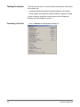
Testing the System . . . . . . . . . . . . . . . . . . . . . . . . . . . . . . . . . . . . . 6-2
Performing a Self-Test . . . . . . . . . . . . . . . . . . . . . . . . . . . . . . . . . 6-2
Testing the Scan System . . . . . . . . . . . . . . . . . . . . . . . . . . . . . . . 6-3
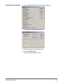
Downloading the Date and Time . . . . . . . . . . . . . . . . . . . . . . . . . . . 6-4
Calibrating the Scanner . . . . . . . . . . . . . . . . . . . . . . . . . . . . . . . . . . 6-5
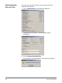
Downloading Firmware . . . . . . . . . . . . . . . . . . . . . . . . . . . . . . . . . . 6-7
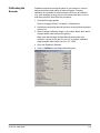
Error Log . . . . . . . . . . . . . . . . . . . . . . . . . . . . . . . . . . . . . . . . . . . . . 6-8
Service Log . . . . . . . . . . . . . . . . . . . . . . . . . . . . . . . . . . . . . . . . . . . 6-9
Selecting a Driver . . . . . . . . . . . . . . . . . . . . . . . . . . . . . . . . . . . . . 6-10
7 Troubleshooting . . . . . . . . . . . . . . . . . . . . . . . . . . . . . . . . . . . . . . 7-1
Indicator Lights . . . . . . . . . . . . . . . . . . . . . . . . . . . . . . . . . . . . . . . . 7-1
Clearing Document Jams . . . . . . . . . . . . . . . . . . . . . . . . . . . . . . . . 7-2
Color Image Quality . . . . . . . . . . . . . . . . . . . . . . . . . . . . . . . . . . . . . 7-3
Error Log . . . . . . . . . . . . . . . . . . . . . . . . . . . . . . . . . . . . . . . . . . . . . 7-4
Testing the System . . . . . . . . . . . . . . . . . . . . . . . . . . . . . . . . . . . . . 7-4
Service Information . . . . . . . . . . . . . . . . . . . . . . . . . . . . . . . . . . . . . 7-4
Moving the Scanner . . . . . . . . . . . . . . . . . . . . . . . . . . . . . . . . . . . . 7-5
Problem Solving . . . . . . . . . . . . . . . . . . . . . . . . . . . . . . . . . . . . . . . 7-8
Appendix A Specifications . . . . . . . . . . . . . . . . . . . . . . . . . . . . . . . A-1
Appendix B Supplies . . . . . . . . . . . . . . . . . . . . . . . . . . . . . . . . . . . . B-1
Index
iv
A-61159 May 2002
1 General Information
Introduction
The Kodak Digital Science™ Scanner 3000/4000 Series includes the
following mid-volume scanner models:
• Scanner 3500
• Scanner 3510
• Scanner 3520
• Color Scanner 3590C
• Color Scanner 4500
These scanners combine the most robust paper feed and transport in
the industry with high image quality and productivity. They are easy to
use and maintain, and handle a broad range of paper weights and
sizes. And they do it all so quietly, you can place them in your
front office.
The Scanner 3520DP and Color Scanner 4500DP include a document
printer that can print a date, time, fixed string, and/or sequential number
on document fronts.
Kodak Digital Science Diagnostic Software (Diagnostic Software) is
included on the CD that is packed with each scanner.
NOTES: The software screens shown in this guide are examples from
the Diagnostic Software. Your software may be different.
The scanner inside and certain replacement parts shown
in this guide may appear different from the ones you have.
However, the actions described in the procedures are
the same.
Site Specifications
Locate the scanner:
• in a clean area with temperature and relative humidity typical of an
office environment
• on a stable, level work surface capable of supporting the
following weights:
- 31.8 kg (70 lb.) for Scanner 3500, Scanner 3510, and
Scanner 3520
- 34 kg (75 lb.) for Color Scanner 3590C and Color Scanner 4500
Provide the following minimum clearances:
• 45.7 cm (18 in.) on the right side (for access for changing lamps,
removing jams, etc.)
• 20.3 cm (8.0 in.) on all other sides around the scanner
A-61159 May 2002
1-1
Safety Information
• When locating the scanner, make sure that the electrical power
outlet is located within 1.52 metres (5 feet) of the scanner and is
easily accessible.
• Before changing a lamp, always power down the scanner and let
it cool a minimum of 10 minutes before proceeding (refer to the
following section, “Warning Labels”).
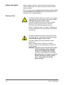
Warning Labels
This label is attached inside your scanner in three places
and is intended to communicate the following message:
CAUTION: Hot surface. Avoid contact.
The label is attached to both ends of the illumination
lamp in the scanner pod, and to one end of the
illumination lamp behind the side access door.
Refer to “Replacing Lamps” in Chapter 5, Maintenance,
for pictures that show the exact locations of this label in
your scanner.
This label is attached on scanner models with printers
and is intended to communicate the following message:
CAUTION: Moving parts. Avoid contact.
The label is attached to the bar behind the printer
access door.
Refer to “Installing an Ink Cartridge” in Chapter 3,
Document Printer, for the exact locations of this label
in your scanner.
WARNING:The printer access door must be in place
and closed during scanner operation,
except when changing the printhead
location or replacing the ink cartridge.
When the printer access door is removed,
DO NOT allow loose clothing, jewelry,
hair, or other objects to enter the
printer opening.
1-2
A-61159 May 2002
Environmental
Information
• The Kodak Digital Science Scanner 3500, Scanner 3510,
Scanner 3520, Color Scanner 3590C, and Color Scanner 4500
are designed to meet worldwide environmental requirements.
• Guidelines are available for the disposal of consumable items that
are replaced during maintenance or service; follow local regulations
or contact Kodak locally for more information.
• The Kodak Digital Science Scanner 3500, Scanner 3510,
Scanner 3520, Color Scanner 3590C, and Color Scanner 4500
contain lead and mercury. Disposal of lead and mercury may be
regulated due to environmental considerations. For disposal or
recycling information, please contact your local authorities or visit
the Electronics Industry Alliance web site at www.eiae.org.
• The product packaging is recyclable.
• Parts are designed for reuse or recycling.
Safety and Regulatory
Agency Approvals
The Kodak Digital Science Scanner 3500, Scanner 3510,
Scanner 3520, Color Scanner 3590C, and Color Scanner 4500
conform to all applicable national and international product safety
and electronic emission regulatory requirements. This includes, but
is not limited to, the following:
• Underwriters Laboratories Inc. listing to UL 1950
• Underwriters Laboratories Inc. listing to CSA C22.2 No. 950
• TUV Rheinland of North America approval to EN60950
• CFR 47 Part 15, Subpart B (FCC Class A)
• Canadian ICES003 Class A
• CE Mark (Europe)
• CISPR22 Class B
• EN55022 Class B
• C-Tick Mark (Australia)
• VCCI Class A
• Taiwan CNS 13438 Class A
A-61159 May 2002
1-3
Electromagnetic
Compliance
Statements
For the United States
This equipment has been tested and found to comply with the limits for
a Class A digital device pursuant to Part 15 of the FCC rules. These
limits are designed to provide reasonable protection against harmful
interference when the equipment is operated in a commercial
environment. This equipment generates, uses, and can radiate radio
frequency energy and, if not installed and used in accordance with
the instruction manual, may cause harmful interference to radio
communications. Operation of this equipment in a residential area is
likely to cause harmful interference in which case the user will be
required to correct the interference at his own expense.
For Japan
This equipment is in the Class A category (Information Technology
Equipment to be used in commercial and/or industrial areas) and
conforms to the standards set by the Voluntary Control Council For
Interference by Information Technology Equipment aimed at preventing
radio interference in commercial and/or industrial areas.
Consequently, when used in a residential area or in an adjacent
area thereto, radio interference may be caused to radio and TV
receivers, etc.
Read the instructions for correct handling.
For Taiwan
1-4
WARNING: This is a class A product. In a domestic environment this
product may cause radio interference in which case the user may be
required to take adequate measures.
A-61159 May 2002
General Features
• Excellent paper handling, image quality, and reliability
• Easy to use and maintain
• Handles a broad range of paper weights and sizes
• Small footprint; fits easily on a desktop or table
• Low noise level
• Easy 30-minute installation
• Kodak Digital Science Diagnostic Software is included
on the CD that is packed with each scanner
• ISIS and TWAIN device drivers are included on the CD
that is packed with each scanner
• International language support
• Simplex and duplex models (Scanner 3520 and
Color Scanner 3590C are duplex only)
• Top/front side printer (Scanner 3520DP/Color Scanner 4500DP only)
• Kodak Perfect Page scanning technology (Scanner 3520D/
Scanner 3520DP only): exclusive Kodak image processing
technology that captures and automatically deskews scanned
images, resulting in consistent, high-quality image output at
production speed
• SCSI-2 connectivity
• Automatic overlap/multifeed detection
• All scanner models support multiple electrical power requirements for
use worldwide
• May be user-calibrated at any time
• Lamp-save option
• Red, green, and blue dropout lamps (imaging elements) available for
special applications
• Color Scanner 3590C provides simplex color and duplex bitonal
(black-and-white) scanning capability in one product; a patch
document enables “on the fly” switching between color and bitonal
scanning (output options include simplex color, simplex bitonal,
duplex bitonal, or duplex with color front and bitonal back)
• Color Scanner 4500 provides simplex and duplex output in color,
bitonal, and “dual stream” (simultaneous duplex color and bitonal)
A-61159 May 2002
1-5
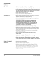
Image Quality
Features
Bitonal Scanners
• Built-in Adaptive Threshold Processing (ATP), image compression,
despeckle, and dithering for bitonal scanning
• Perfect Page scanning technology (Scanner 3520D/Scanner 3520DP
only) with better edge detection (which assists in providing superior
deskew and ultimately sharper, crisper characters)
• Image capture resolution: 600 dpi
• Image output resolution: 200 dpi and 300 dpi
Color Scanners
• Built-in Adaptive Threshold Processing (ATP), image compression,
despeckle, and dithering for bitonal scanning
• Auto-color balancing (auto-white balancing) to ensure good color
balance after calibration
A white spot just outside the imaging area (located on the
front imaging guide for Color Scanner 3590C and on the
front and rear imaging guides for Color Scanner 4500D and
Color Scanner 4500DP) is used as a constant reference to
compensate for changes in lamp brightness
• Pixel and color correction for the best color image quality
• Multiple color tables available from within the Diagnostic Software
(for the TWAIN device driver only) to optimize color image quality
(Color Scanner 4500 only)
• Dual stream (simultaneous color and bitonal) output available
(Color Scanner 4500 only)
• JPEG compression allows images to be viewed in many
image viewers
• Image capture resolution: 600 dpi for bitonal scanning
(Color Scanner 3590C only); 150 dpi for color scanning
• Image output resolution: 200 dpi and 300 dpi for bitonal scanning
(Color Scanner 3590C only); 100 dpi and 150 dpi for color scanning
Paper Transport
Features
• Automatic and manual feeding
• Top entry, bottom exit paper transport
• Multifeed detection (by document length in Scanner 3500; by
document length and/or document thickness in Scanner 3510,
Scanner 3520, Color Scanner 3590C, and Color Scanner 4500)
• Automatic feeder with operator-assisted “infinite” and
single-sheet feeding
1-6
A-61159 May 2002
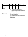
Standard
Configurations
Feeder and output tray
specifications by product
Scanner
3500
Automatic 150-sheet feeder
x
Automatic 250-sheet feeder
250-sheet output tray
350-sheet enhanced
output tray
Scanner
3510
Scanner
3520
Color Scanner Color Scanner
3590C
4500
x
x
x
x
x
x
x
x
x
NOTE: The Scanner 3500 and Color Scanner 3590C can
accommodate the Kodak Digital Science Feed Module 250
(automatic 250-sheet feeder) and the Kodak Digital Science
Enhanced Output Tray (350-sheet tray). Contact your Kodak
Reseller to purchase an upgrade kit.
Maintenance/
Troubleshooting
Features
• Easily replaceable lamps, rollers, and other wear parts
• Easy one-step paper jam clearance
• User-accessible error logs via the Kodak Digital Science Diagnostic
Software that is included on the CD that is packed with each scanner
• LED indicators for power, ready, paper jam, and error/service
operating conditions
A-61159 May 2002
1-7
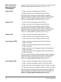
Paper Transport
Speed/Capacity
(Throughput)
A page fed into the scanner can be up to 30.5 cm (12 in.) wide, but the
maximum image width that is captured is 29.7 cm (11.7 in.).
Scanner 3500
• 75 ppm: mixed-size, landscape-oriented, 200 dpi
• 50 ppm: letter-size (or A4), landscape-oriented, 300 dpi
The Scanner 3500’s automatic document feeder is capable of
150-sheet feeding, and operator-assisted “infinite” and single-sheet
feeding, of 75g (20 lb.) paper having a length of 6.4 to 43.2 cm
(2.5 to 17 in.) and a width of 8.9 to 30.5 cm (3.5 to 12 in.).
Scanner 3510
• 75 ppm: mixed-size, landscape-oriented, 200 dpi
• 85 ppm: letter-size (or A4), landscape-oriented, 200 dpi
• 57 ppm: letter-size (or A4), landscape-oriented, 300 dpi
The Scanner 3510’s automatic document feeder is capable of
250-sheet feeding, and operator-assisted “infinite” and single-sheet
feeding, of 75g (20 lb.) paper having a length of 6.4 to 43.2 cm
(2.5 to 17 in.) and a width of 8.9 to 30.5 cm (3.5 to 12 in.).
Scanner 3520
• 75 ppm: mixed-size, landscape-oriented, 200 dpi
• 85 ppm: letter-size (or A4), landscape-oriented, 200 dpi
• 57 ppm: letter-size (or A4), landscape-oriented, 300 dpi
Color Scanner 3590C
• 75 ppm: mixed-size, landscape-oriented, 200 dpi bitonal or
100 dpi color output
• 50 ppm: mixed-size, landscape-oriented, 300 dpi bitonal or
150 dpi color output
• 85 ppm: letter-size (or A4), landscape-oriented, 200 dpi bitonal or
100 dpi color output
• 57 ppm: letter-size (or A4), landscape-oriented, 300 dpi bitonal or
150 dpi color output
The Color Scanner 3590C’s automatic document feeder is capable of
150-sheet feeding, and operator-assisted “infinite” and single-sheet
feeding, of 75g (20 lb.) paper having a length of 6.4 to 43.2 cm
(2.5 to 17 in.) and a width of 8.9 to 30.5 cm (3.5 to 12 in.).
Color Scanner 4500
• 75 ppm: mixed-size, landscape-oriented, 100 dpi color output
• 50 ppm: mixed-size, landscape-oriented, 150 dpi color output
• 85 ppm: letter-size (or A4), landscape-oriented, 100 dpi color output
• 57 ppm: letter-size (or A4), landscape-oriented, 150 dpi color output
The Color Scanner 4500’s automatic document feeder is capable of
250-sheet feeding, and operator-assisted “infinite” and single-sheet
feeding, of 75g (20 lb.) paper having a length of 6.4 to 43.2 cm
(2.5 to 17 in.) and a width of 8.9 to 30.5 cm (3.5 to 12 in.).
1-8
A-61159 May 2002
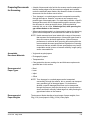
Preparing Documents
for Scanning
• A batch of documents to be fed into the scanner must be arranged so
that the leading edges of all documents are aligned and centered
under the automatic paper feeder; this allows the feeder to introduce
documents into the scanner one at a time.
• Torn, damaged, or crushed pages can be transported successfully
through the scanner. However, no scanner can transport every
possible type of damaged paper. If in doubt about whether a specific
damaged document can be transported through the scanner, place
the document in a clear protective sleeve. Sleeves should be
manually fed, one at a time, folded edge first, while pressing the
gap release button on the scanner.
• When scanning documents in a clear protective sleeve, the input tray
guides must be adjusted to accommodate the width of the sleeve.
NOTE: Kodak scanners have been tested with a range of documents
that represent the broad spectrum of document types found in
the most common business applications. Optimal scanner
performance is achieved when scanning documents within the
recommended document specifications listed below. Scanning
documents that are outside of these specifications may lead to
undesirable results in terms of scanner reliability, image quality,
and/or consumable life.
Acceptable
Document Materials
• Virgin and recycled papers
• Photographic papers
• Transparencies
• Clear protective sleeves meeting size and thickness requirements
specified later in this section
Recommended
Paper Types
• Bond
• Laser
• Inkjet
• Offset
NOTE: Torn, damaged, or crushed pages can be transported
successfully through the scanner, but no scanner can transport
every possible type of damaged paper. If in doubt about
whether a specific damaged document can be transported
through the scanner, place the document in a clear protective
sleeve and feed it manually, folded edge first, while pressing the
gap release button on the scanner.
Recommended
Paper Weights
A-61159 May 2002
The document feeder handles a broad range of paper weights, from
50g (13 lb.) bond paper to 200g (110 lb.) index paper.
1-9
Acceptable
Document Sizes
• Length:
- Maximum of 66 cm (26 in.), operator-assisted document feeding
and stacking
NOTE: The maximum length for unattended document feeding is
43.2 cm (17 in.).
- Minimum of 6.4 cm (2.5 in.)
• Width:
- Maximum of 29.7 cm (11.7 in.) (A3 width)
- Minimum for automatic feeding of 8.9 cm (3.5 in.)
- Minimum for manual feeding of 6.4 cm (2.5 in.)
Acceptable
Document Thickness
• 0.038 mm (0.0015 in.) to 0.76 mm (0.030 in.)
• For multifeed detection by document thickness, paper must be
0.05 to 0.18 mm (0.002 to 0.007 in.) thick
NOTE: Document batches must be of uniform thickness to use the
multifeed detection feature successfully.
Paper Inks for
Scanned Documents
NOTE: All inks on the paper must be dry before scanning is started.
• Standard offset printing
• Inkjet printer
• Thermal transfer
• Handwriting inks
Acceptable Paper
Correction Fluids for
Scanned Documents
• Liquid Paper
• Tipp-Ex
• Wite-out
• Other correction fluids similar to the above
Maximum Document
Batch Height for
Automatic Feeding
• When feeding batched documents using the Feed Module 150
(included with the Scanner 3500 and Color Scanner 3590C), the
maximum height of the batched documents is 15.2 mm (0.6 in.)
or approximately 150 sheets of 75g (20 lb.) paper.
• When feeding batched documents using the Feed Module 250
(included with the Scanner 3510, Scanner 3520, and
Color Scanner 4500), the maximum height of the batched
documents is 25.4 mm (1.0 in.) or approximately 250 sheets
of 75g (20 lb.) paper.
1-10
A-61159 May 2002
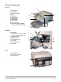
Scanner Components
External
:
1
2
3
4
5
6
7
8
9
10
11
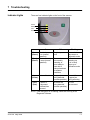
1
Release latch
Feed module
Input tray extender
Pod
Output tray
Indicator lights
Pause button
Resume button
Power switch
Side access door
Printer door (Scanner 3520DP
and Color Scanner 4500DP only)
2
11
3
4
10
5
Internal
6
7
8
9
1
1 Drive rollers
2 Ink blotter strips (Scanner 3520DP
and Color Scanner 4500DP only)
3 Paper path sensors
4 Separator roller
5 Front imaging guide
6 Front lamp
7 Rear imaging guide
8 Rear lamp
2
3
8
4
7
5
3
6
Rear
1 SCSI ID switch
2 Power cord connector
3 SCSI connectors
1
2
3
A-61159 May 2002
1-11
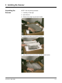
2 Installing the Scanner
Unpacking the
Scanner
NOTE: Save all packing materials.
1. Carefully cut the tape.
2. Open the box.
3. Remove the output tray and set it aside.
4. Remove the foam cover and set it aside.
5. Open the bag and remove the materials packed inside.
A-61159 May 2002
2-1
6. Use two people to lift and move the scanner to a stable, level
work surface.
7. Replace the packing materials.
8. Store the box for possible future use.
9. Read the “Read Me Now” document that is taped to the top of
your scanner.
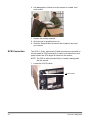
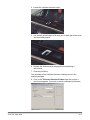
SCSI Connection
Two SCSI-2, 50-pin, high-density D-Shell connectors are provided on
the rear panel for SCSI connectivity. A switch is provided on the rear
panel to select the SCSI target ID number for the scanner.
NOTE: The SCSI-2 cable (standard 50-pin, D-shell) is not supplied
with the scanner.
1. Locate the SCSI ID switch.
SCSI ID switch
2-2
A-61159 May 2002
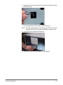
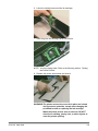
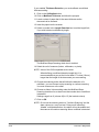
2. Use the blade of a small screwdriver to press the switch and set the
SCSI ID number.
For most applications, this number should be set to “1”.
NOTE: The scanner should be the only device in the SCSI chain. If you
change the SCSI ID number after installation, reboot your PC.
3. Connect the SCSI-2 cable to the scanner.
4. Connect the other end of the cable to your computer.
A-61159 May 2002
2-3
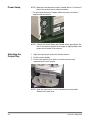
Power Setup
NOTE: Make sure that the power outlet is located within 1.52 metres (5
feet) of the scanner and is easily accessible.
• For the United States and Canada, attach the power cord that is
supplied with the scanner.
NOTE: Outside the United States and Canada, where appropriate, the
user or the scanner supplier shall supply an appropriately rated
power cord to attach to the scanner.
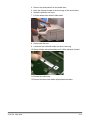
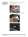
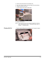
Attaching the
Output Tray
1. Align the output tray's center slot with the scanner.
2. Lift the scanner slightly.
3. Position the output tray so that it is under the scanner and
supported by the work surface.
NOTE: Slide the output tray in or out as needed to accommodate
different document sizes.
2-4
A-61159 May 2002
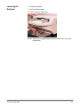
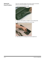
Lowering the
Deflector
1. Locate the deflector.
2. Pull the deflector down.
3. Lower it onto the output tray.
NOTE: When scanning lightweight documents that tend to curl, raise
the deflector.
A-61159 May 2002
2-5
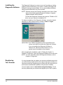
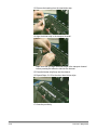
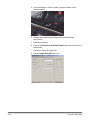
Installing the
Diagnostic Software
The Diagnostic Software is an easy-to-use tool for setting up, testing,
updating, and troubleshooting your scanner. Installing the Diagnostic
Software is strongly recommended. It is an easy, standard Windows
setup procedure that takes only a few minutes.
NOTE: Software screens and functions described in this User’s Guide
apply to the Kodak-supplied Diagnostic Software. Integratorsupplied software will be different.
To install the Diagnostic Software and select the TWAIN or ISIS
driver, see your scanner’s Installation CD.
For fastest installation of the Diagnostic Software, accept the default
selections on each setup screen by clicking on Next or I Agree.
IMPORTANT: The TWAIN-compatible and ISIS-compatible device
drivers are loaded from within the Diagnostic Software.
If you are installing the Diagnostic Software in
Windows 95, Microsoft Internet Explorer v4.0 or
greater must be installed on the computer.
After completing the installation, refer to “Testing the System” in
Chapter 6, Diagnostics. Open the Diagnostic Software to run both tests.
NOTE: For more information about the Diagnostic Software, refer to
Chapter 6, Diagnostics.
Registering
Your Scanner
It is very important that you register your scanner so Kodak can provide
you with the best possible service and support that helps maintain your
continuous scanning. Registering your scanner will help us provide you
with firmware and hardware updates as they become available.
You can register online at www.kodak.com/go/docimaging. Or see
the form packed with your scanner and register by fax, mail, or phone.
2-6
A-61159 May 2002
3 Document Printer
The Scanner 3520DP and Color Scanner 4500DP include a factoryinstalled, pre-configured document printer. The printer operates at full
scanner speed, and prints on the document before scanning on the
front side of the document (top side as placed in the input tray). The
document printer can add a date, time, fixed string, and/or sequential
number on document fronts. Printing is controlled through software.
IMPORTANT: Clean the scanner’s internal components daily when you
use the document printer.
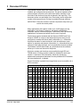
Overview
Many applications with capture needs up to 10,000 pages per day,
particularly in the finance, insurance, and public administration
industries, require a document printer. Furthermore, forms processing
applications in all areas can benefit from the use of a printer.
The document printer included with the Scanner 3520DP and Color
Scanner 4500DP is unique in that the document print string can be
configured to include both literal (static) information (i.e., information
that stays the same for each document, such as batch name, scan
station, or operator) and dynamic information (i.e., information that may
change for each page scanned, such as sequential document number).
The software controls static fields; any information that the software
allows you to enter can be sent to the printer.
All printer controls and functions are accessible through ISIS and
TWAIN drivers. Printing must be enabled or disabled for each scan
session. A maximum of 40 characters, which can include any
alphanumeric and special characters from the printable ASCII character
set (see chart below), is allowed.
Printer information is posted to an image footer record, accessible via a
SCSI command.
Printable ASCII Character Set
A-61159 May 2002
blank
!
“
#
$
%
&
‘
À
Á
Â
Ã
Ä
Å
Æ
Ç
(
)
*
+
,
-
.
/
È
É
Ê
Ë
Ì
Í
Î
Ï
0
1
2
3
4
5
6
7
Ð
Ñ
Ò
Ó
Ô
Õ
Ö
×
8
9
:
;
<
=
>
?
Ø
Ù
Ú
Û
Ü
Ý
Þ
ß
@
A
B
C
D
E
F
G
à
á
â
ã
ä
å
æ
ç
H
I
J
K
L
M
N
O
è
é
ê
ë
ì
í
î
ï
P
Q
R
S
T
U
V
W
ð
ñ
ò
ó
ô
õ
ö
÷
X
Y
Z
[
\
]
^
_
ø
ù
ú
û
ü
ý
þ
ÿ
`
a
b
c
d
e
f
g
¡
¢
£
¤
¥
¦
§
h
i
j
k
l
m
n
o
©
ª
«
¬
-
®
¯
p
q
r
s
t
u
v
w
±
²
³
´
µ
¶
·
x
y
z
{
|
}
~
‘
¹
º
»
¼
½
¾
¿
’
¨
°
¸
3-1
Dynamic Print Field
Options
Sequential Document Number—the starting sequential document
number is specified by the host during job setup, and has a maximum
of nine digits. You may suppress the printing of leading zeros. The
sequential number increments by one for each document scanned.
If the sequential number rolls over (e.g., three digits are specified,
and the number 1000 is reached), the scanner stops and displays
an error.
Date—this field can be specified to be in MMDDYYYY, DDMMYYYY,
or YYYYMMDD format. Date delimiters (dash, slash, comma, or
blank separators) may be specified and will be counted as part of
the 40-character string length limit.
Time—this field is in the format HH:MM, where HH is in 24-hour format.
The hours and minutes are separated with a colon (:). This field
therefore uses five characters of the 40 character limit.
Control of the Printer—any combination of dynamic and static fields is
allowed as long as the total print string does not exceed 40 characters.
There is no “default” print string. The format of the print string, along
with the starting sequential document number, if used, is created on
the host and is downloaded to the scanner at the beginning of each
scan session.
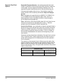
Characters can be printed in two orientations, Cine and Comic, and two
sizes, Large and Small. Small is approximately two-thirds the size of
normal, and is designed to fit 10 characters per inch when printed in
Comic orientation.
The resolution of the character fonts is 96 dpi across the width of the
scanner. However, the font resolution varies with the direction that the
paper is fed into the scanner. This variable allows the creation of an
easy-to-read character string. The approximate resolution of the printed
output is shown below.
Resolution (dpi)
3-2
Large
Small
Cine
63 dpi
85 dpi
Comic
85 dpi
115dpi
A-61159 May 2002
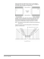
Printing cannot be done within 0.89 cm (0.35 in.) of the leading or
trailing edge of the document. It prints in either Cine (no rotation) or
Comic (90q rotation) orientation, as shown below.
Changes to the print string, other than automatic, sequential number
advances, require a host SCSI command to restart the printer. You
must initiate a change between documents or batches. Changes
cannot be done automatically or between documents “on the fly.”
NOTE: The minimum document width for using the document printer is
14 cm (5.5 in.).
The document printer can be manually placed in 18 horizontal print
positions, as shown below.
A-61159 May 2002
3-3
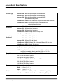
Printer Specifications
Characteristic
Maximum lines
Description
1
Print locations (horizontal) 18, manually set
Print locations (vertical)
Set by host
Print orientation
Cine, Comic
Font size
2 selectable, normal and small
Ink cartridge
HP51604A or compatible
Print side
Front (pre-scan)
Minimum printing distance 0.89 cm (0.35 in.)
from document edge
Setting Up the
Document Printer
Static fields available
User-specified via host
Dynamic fields available
Up to nine-digit sequential document
number, date, four-digit time
Languages supported
Any phonetic language (for example,
Danish, Dutch, English, Finnish,
French, German, Italian, Norwegian,
Portuguese, Spanish, Swedish)
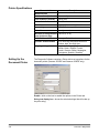
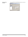
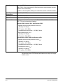
The Diagnostic Software contains a Printer tab to set up options for the
document printer (Scanner 3520DP and Scanner 4500DP only).
Enable—click on the box to enable the options in the Printer tab.
String text display box—shows the selected strings that will make up
the print string.
3-4
A-61159 May 2002
String item selection list—choose the item(s) that you want included
in the print string. Select one of the three Date formats, Time, Counter,
Message, and/or Blanks. Click on the Add button for each item
selected. The string will appear in the text display box. Select a string
and click on the Delete button to remove the string from the string text
display box.
Counter—indicates the number at which the counter will begin printing.
Counter Format—allows you to set the number of digits (1-9) that the
counter will count to until it rolls over (e.g., if “3” is specified, the counter
will print sequential numbers up to 999, and the next scan counter
number will be 000).
Select Display Leading Zeroes in the Counter Format drop-down box
if you want leading zeroes in the counter to print. Choose Suppress
Leading Zeroes if you do not want leading zeroes to print.
Message—allows you to enter a text message that will be printed.
The number of characters allowed depends on the number of
characters specified in the print string.
Date Delimiter—allows you to specify the way the date will be printed.
Font—allows you to select the font the string will be printed with: Large
Comic, Large Cinema, Small Comic, or Small Cinema.
Y Offset—allows you to specify how far from the left margin you want
the string to be printed. Specify the desired units of measure: Inches,
Centimeters, Picas, Points, 20th of Points, or Pixels.
Printer Test—allows you to print the string on a document so you can
verify any changes before saving them.
Defaults—allows you to return all values to their factory defaults.
Copy—allows you to copy the values you specified for the front camera
and enter them for the rear camera, if Duplex is specified in the
Scan Mode field.
OK—saves the values and closes this dialog box. The values are sent
to the scanner when scanning is started.
Cancel—closes this dialog box without saving any changes. All
previous values are restored.
A-61159 May 2002
3-5
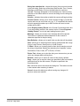
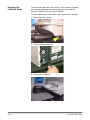
Opening the
Printer Access Door
1. Locate the printer access door on the top of the scanner.
2. Pull the printer access door latches toward you to release the door.
3. Lift the printer access door and set it aside.
WARNING:The printer access door must be in place and closed
during scanner operation, except when changing the
printhead location or replacing the ink cartridge.
When the printer access door is removed, DO NOT
allow loose clothing, jewelry, hair, or other objects to
enter the printer opening.
3-6
A-61159 May 2002
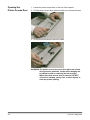
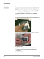
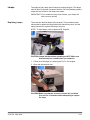
Purging an Ink
Cartridge
One ink cartridge is included with the Scanner 3520DP and
Color Scanner 4500DP. Additional ink cartridges may be purchased
from an office supply retailer near you.
You must purge the ink cartridge before installing it.
1. Remove the ink cartridge from the box and inner wrappings.
2. Hold the cartridge and insert a straightened paper clip into the larger
hole on the top of the ink cartridge.
3. Rotate the ink cartridge until the bottom is face up.
4. Gently press the paper clip against the side of the ink bladder
until a small bead of ink appears on the ink flow point on the ink
cartridge bottom.
CAUTION: Do not puncture the ink bladder with the paper clip.
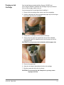
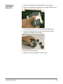
5. Remove the paper clip.
6. Allow the ink bead to absorb back into the ink cartridge.
7. Blot the excess ink with a lint-free tissue.
CAUTION: Do not touch the ink flow point or you may cause
improper ink flow.
A-61159 May 2002
3-7
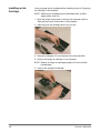
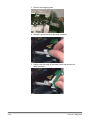
Installing an Ink
Cartridge
You must purge the ink cartridge before installing it (refer to “Purging an
Ink Cartridge” in this chapter).
NOTE: Additional ink cartridges may be purchased from an office
supply retailer near you.
1. Open the printer access door on the top of the scanner (refer to
“Opening the Printer Access Door” in this chapter).
2. Slide the green ink cartridge carrier out of its slot.
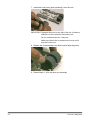
3. Raise the locking bar if it is not already in the raised position.
4. Remove the empty ink cartridge, if one is present.
NOTE: Dispose of empty ink cartridges properly. Do not incinerate
ink cartridges.
5. Insert a new, purged ink cartridge.
3-8
A-61159 May 2002
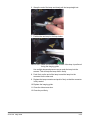
6. Lower the locking bar around the ink cartridge.
7. Slide the green ink cartridge carrier into its slot.
NOTE: You may change slots. Refer to the following section, “Setting
the Printer Position.”
8. Replace the printer access door and close it.
WARNING:The printer access door must be in place and closed
during scanner operation, except when changing the
printhead location or replacing the ink cartridge.
When the printer access door is removed, DO NOT
allow loose clothing, jewelry, hair, or other objects to
enter the printer opening.
A-61159 May 2002
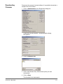
3-9
Setting the
Printer Position
There are 18 possible positions for the printer. Make sure that the
printer is in the correct position for your documents.
1. Locate the printer positioning slots.
2. Determine which position is suitable for your printing needs.
3. Slide the green ink cartridge carrier out of its slot.
4. Slide the green ink cartridge carrier into the desired slot.
3-10
A-61159 May 2002
Document Printing
Problems
If you are having problems printing on scanned documents:
• The tip of the ink cartridge may be plugged. Purge (prime) the ink
cartridge (refer to “Purging an Ink Cartridge” in this chapter). If the ink
still does not flow properly, replace the ink cartridge. Dispose of used
ink cartridges properly.
• Verify that the ink cartridge is not empty. The ink bladder inside the
cartridge is flat when it is empty.
• Make sure that the ink cartridge is properly installed in the
document printer.
• Make sure that the ink cartridge is located in the correct position
for printing.
• Make sure that the ink cartridge carrier is properly seated in its slot.
• Verify that all printer connectors are securely fastened and that the
printer cables are not folded or creased.
• Verify that the printer has been enabled through the Diagnostic
Software and that the expected print string has been specified.
• Conduct a print test diagnostic using the Diagnostic Software.
Document Printer
Maintenance
The ink cartridges, ink blotter strips, and ink cartridge carriers used in
the document printer need replacing occasionally.
Expected Life of
Document Printer
Components
• Document printer ink cartridge: approximately 650,000 characters
per cartridge.
• Ink blotter strips: replace as necessary when soiled.
• Ink cartridge carrier: approximately 600,000 pages.
Replacing an
Ink Cartridge
Refer to “Installing an Ink Cartridge” in this chapter for information
about replacing an empty ink cartridge.
NOTE: Additional ink cartridges may be purchased from an office
supply retailer near you.
A-61159 May 2002
3-11
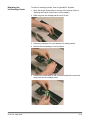
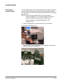
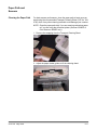
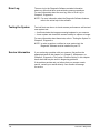
Replacing the
Ink Blotter Strips
The ink blotter strips collect ink overflow. They should be replaced
as necessary. Replacement blotter strips are included with the
Scanner 3520DP and Color Scanner 4500DP.
To order additional ink blotter strips, refer to Appendix B, Supplies.
1. Power down the scanner.
2. Disconnect the power cord.
3. Remove the output tray.
3-12
A-61159 May 2002
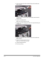
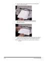
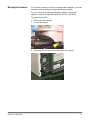
4. Remove any documents from the feeder area.
5. Move the scanner forward to the front edge of the work surface.
6. Grasp the pod with one hand.
7. Pull the release latch with the other hand.
8. Gently lower the pod.
9. Locate the four ink blotter strips (two short, two long).
10. Grasp a blotter strip and carefully pull it off the transport channel.
11. Discard the soiled strip.
12. Remove the three other blotter strips and discard them.
A-61159 May 2002
3-13
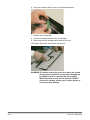
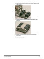
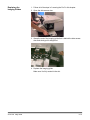
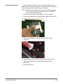
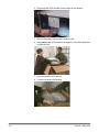
13. Remove the backing from the new blotter strip.
14. Align the blotter strip in the transport channel.
Make sure that you align the blotter strips in the transport channel
before pressing the adhesive side into the channel.
15. Press the blotter strip firmly into the channel.
16. Repeat Steps 13-15 for the other three blotter strips.
17. Close the pod firmly.
3-14
A-61159 May 2002
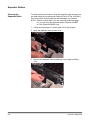
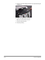
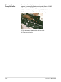
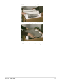
Replacing the
Ink Cartridge Carrier
To order ink cartridge carriers, refer to Appendix B, Supplies.
1. Open the printer access door on the top of the scanner (refer to
“Opening the Printer Access Door” in this chapter).
2. Slide the green ink cartridge carrier out of its slot.
3. Raise the locking bar if it is not already in a raised position.
4. Remove the ink cartridge, if one is present.
5. Squeeze the metal strips on the connector and pull the connector
away from the ink cartridge carrier.
A-61159 May 2002
3-15
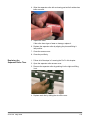
6. Push the connector firmly into a new ink cartridge carrier.
7. Replace the ink cartridge.
8. Lower the locking bar around the ink cartridge.
9. Slide the green ink cartridge carrier back into its slot.
10. Replace the printer access door and close it.
WARNING:The printer access door must be in place and closed
during scanner operation, except when changing the
printhead location or replacing the ink cartridge.
When the printer access door is removed, DO NOT
allow loose clothing, jewelry, hair, or other objects to
enter the printer opening.
3-16
A-61159 May 2002
4 Using the Scanner
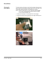
Powering Up/Down
the Scanner
• Press the button on the scanner’s bottom right side to power it up.
or
• Press the button on the scanner’s bottom right side to power it down.
After you power up the scanner, the green indicator light flashes.
When the green indicator light stops flashing and the lamps have
been on at least 30 seconds, the scanner is ready to begin scanning.
IMPORTANT: Always power up the scanner to its ready state before
powering up the host computer.
Starting and
Stopping Scanning
Before you start scanning, make sure that the lamps have been on for
at least 30 seconds.
Scanning is controlled by integration software developed for your
application (the dialog box shown below is from the Kodak Digital
Science Diagnostic Software that is included with the scanner).
To start and stop scanning, refer to the documentation provided with
your integration software.
A-61159 May 2002
4-1
Pausing and
Resuming Scanning
• Press the Pause button on the scanner to stop scanning.
• Press the Resume button on the scanner to restart scanning after it
has been paused.
Note that the Resume function is active only for a specific,
configurable amount of time after scanning is paused.
Resume button
Pause button
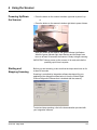
Automatic Feeding
To scan a batch of documents, follow the guidelines for size, type,
quantity, etc., in Chapter 1, General Information.
For faster throughput, feed documents into the feeder in landscape
orientation (longer side as the leading edge).
1. Align the leading edges of the stacked documents.
2. Position the leading edge of the documents just under the
feed module.
3. Adjust the output tray.
4. Start scanning.
For fastest throughput of a batch of same-size documents, you can
enable a special scanning mode for documents that are the same
size (length and width). Refer to “Scanning Same-Size Documents”
in this chapter.
4-2
A-61159 May 2002
Continuous Feeding
Continuous feeding allows you to place additional batches of
documents in the feeder for “infinite” feeding (with operator assistance).
• When only a few documents from one batch remain in the feeder,
place the next batch under those documents.
Scanning Same-Size
Documents
Your scanner has a selectable function that enables faster scanning of
documents that are the same size (length and width). When enabled,
this function speeds the scanning of same-size documents by
approximately 13%.
Same-size document scanning is designed for documents that are:
• the same size (length and width)
• the same orientation
• autofed, not manually fed
• centered in the paper transport
• fitted within the side transport guides with minimal skew
Enabling Same-Size
Document Scanning
1. Click in the Same Size Documents check box so that a check
mark appears.
2. Click on OK.
A-61159 May 2002
4-3
Disabling Same-Size
Document Scanning
When scanning documents of mixed sizes, be sure to disable the
same-size documents scanning function.
1. Click on the Same Size Documents check box to remove the
check mark.
2. Click on OK.
Manual Feeding
Follow the guidelines for document size, type, weight, quantity, etc., in
Chapter 1, General Information.
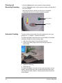
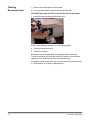
Damaged Documents
1. Place damaged documents into a protective sleeve.
4-4
A-61159 May 2002
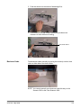
2. Feed the sleeve into the scanner folded edge first.
3. Press and hold the gap release button (this provides more
clearance to ease document feeding).
Gap release button
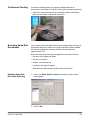
Business Cards
Feed business cards manually by placing them directly under a feed
roller on either side of the feed module.
NOTE: You cannot manually scan business cards this way on the
Scanner 3520 or the Color Scanner 4500.
A-61159 May 2002
4-5
Switching
Scan Modes
(Color Scanner 3590C
Only)
The Color Scanner 3590C contains two cameras: one captures bitonal
(black-and-white) images on both sides of documents and the other
captures color images on the front side of documents. Only one camera
at a time can be in position to capture images. You can control the
switch between bitonal and color scanning quickly and easily, on the fly,
by feeding the Kodak-designed patch document into the scanner in
portrait or landscape orientation.
NOTE: The patch document is in a .pdf file is on the Installation CD.
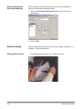
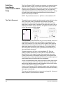
The Patch Document
The patch document contains two identical patch codes (similar to a bar
code). One patch code is positioned to be scanned if the patch
document is fed in portrait orientation (shorter side first). The other
patch code is positioned to be scanned if the patch document is fed in
landscape orientation (longer side first). The patch document must be
fed into the scanner as shown below.
When you feed the patch document into your Color Scanner 3590C, the
scanner detects the patch code and switches to the opposite scan
mode. If the scanner is in color scan mode, the patch code causes a
switch to bitonal scanning; if the scanner is in bitonal scan mode, the
patch code causes a switch to color scanning. For a mixed batch of
color and bitonal documents, place a patch document between your
color and bitonal documents.
The patch document .pdf file is on the Installation CD. Print the
quantity of patch documents you need (refer to “Patch Document
Specifications” in this chapter) using a black-and-white laser printer.
A laser printer delivers the sharpest image quality on the patch code.
The performance of inkjet-printed patch documents and photocopies of
laser-printed patch documents cannot be guaranteed.
You do not need different patch code documents to switch from bitonal
to color scanning and vice versa. The patch document is designed to
switch to the opposite scanning mode, regardless of the current mode.
Only one type of patch document is required.
Once the Color Scanner 3590C detects the patch code, it takes three to
four seconds for the scanner to switch cameras, then document feeding
starts again automatically.
The scanned patch document is not saved as an image file. It does not
take up space on your hard drive or network.
4-6
A-61159 May 2002
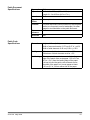
Patch Document
Specifications
Patch Code
Specifications
A-61159 May 2002
Paper color
White
Paper size
Width: 8.8 to 29.3 cm (3.5 to 11.7 in.)
Length: 21.3 to 42.5 cm (8.5 to 17 in.)
Ink color
Black
Type of
printer
A laser printer is recommended.
Contents
The patch document should contain only the two patch
codes (one for portrait, one for landscape). No other
images or text should be on the patch document.
Skew
tolerance
20x
Read rate
99%
Dimensions
Height: > 2.5 cm (1.0 in.)
Width of narrow elements: 0.175 cm (0.07 in.), ±10%
Width of wide elements: 0.45 cm (0.18 in.), ±10%
Quality
Reflectance of white elements must be > 65%
Reflectance of black elements must be < 5%
Positioning
When you print the patch document, the leading
edge of the patch code must appear 1.25 to 3.8 cm
(0.5 to 1.5 in.) from the leading edge of the paper.
It is best to have the patch code centered across
the width of the paper, but it must appear at least
1.25 cm (0.5 in.) in from either side of the paper.
4-7
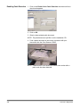
Enabling Patch Detection
1. Click on the Enable Color Patch Detection check box so that a
check mark appears.
2. Click on OK.
3. Obtain a laser-printed patch document.
NOTE: The patch document .pdf file is on the Installation CD.
4. Feed a patch document in the correct orientation with your
documents into the Color Scanner 3590C.
NOTE: It takes three to four seconds to switch scan modes after a
patch code has been detected.
4-8
A-61159 May 2002
Disabling Patch
Detection
A-61159 May 2002
• Click on the Enable Color Patch Detection check box to remove the
check mark.
4-9
Multifeed Detection
Your scanner has a selectable function that can alert you when a
multifeed occurs. A multifeed is when two or more documents pass
through the feeder simultaneously.
NOTE: The Scanner 3500 has a different multifeed detection setup
than the Scanner 3510, Scanner 3520, Color Scanner 3590C,
or Color Scanner 4500.
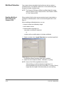
Enabling Multifeed
Detection for the
Scanner 3500
When enabled, this function causes an alarm tone to sound when a
multifeed is detected (alarm volume must be set higher than 0--see
Step 3).
When enabling multifeed detection, you can
• choose to detect a multifeed by length
• set the alarm volume
• choose whether scanning is to
- stop when a multifeed is detected
or
- continue with an audible alarm to indicate multifeeds
1. Select a number in the Length Detection box to set the length limit.
The Multifeed Stops Scanning check box is enabled.
2. Select the unit of measure (inches, millimeters, or pixels).
NOTE: Users of the ISIS-compatible device driver:
When defining a multifeed detection length limit, it is
recommended that you set the limit at least 0.7 inches (18 mm)
longer than the length of the documents you are scanning.
4-10
A-61159 May 2002
3. Choose an Alarm Volume setting under the Multifeed Stops
Scanning check box for an alarm tone that sounds when a multifeed
is detected.
Settings range from 0 (volume off) to 15 (the loudest volume).
4. Click on OK.
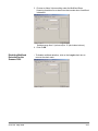
Disabling Multifeed
Detection for the
Scanner 3500
A-61159 May 2002
• To disable multifeed detection, click on the Length check box to
remove the check mark.
4-11
Enabling Multifeed
Detection for Scanners
3510 and 3520 and
Color Scanners 3590C
and 4500
When enabled, this function causes an alarm tone to sound when a
multifeed is detected (alarm volume must be set higher than 0--see
Step 16).
When enabling multifeed detection, you can
• choose to detect a multifeed by length and/or thickness
• set the alarm volume
• choose whether scanning is to
- stop when a multifeed is detected
or
- continue with an audible alarm to indicate multifeeds
Multifeed detection is enabled partly on the scanner itself and partly in
the scanning software.
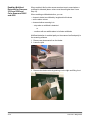
1. Remove any documents from the feeder.
2. Lower the pod.
3. Remove the feed module by pushing it to the right and lifting it out.
4-12
A-61159 May 2002
4. Locate the multifeed detection button.
5. Use a small pointed object, such as a pen, to push the button down
into the enable position.
6. Replace the feed module by aligning the pins and fitting it
into position.
7. Close the pod firmly.
The remainder of the multifeed detection enabling occurs in the
scanning software.
8. Click on the Thickness Detection Enable check box so that a
check mark appears, if you wish to detect multifeeds by thickness.
A-61159 May 2002
4-13
If you enabled Thickness Detection, you must calibrate a multifeed
thickness setting.
9. Click on the Calibration button.
10. Click on Multifeed Thickness and follow the prompts.
11. Locate a sheet of paper that is the same thickness as the
documents to be scanned
12. Insert the paper into the scanner.
13. Select a number in the Length Detection box to set the length limit,
if you wish to detect multifeeds by length.
The Multifeed Stops Scanning check box is enabled.
14. Select the unit of measure (inches, millimeters, or pixels).
NOTE: Users of the ISIS-compatible device driver:
When defining a multifeed detection length limit, it is
recommended that you set the limit at least 0.7 inches (18 mm)
longer than the length of the documents you are scanning.
15. Choose the scanning action that will follow the detection of a
multifeed—you can choose to stop scanning or continue scanning.
You must choose one or the other.
16. Choose an Alarm Volume setting under the Multifeed Stops
Scanning check box for an alarm tone that sounds when a multifeed
is detected.
Settings range from 0 (volume off) to 15 (the loudest volume).
17. Click on OK.
NOTE: Do not set the scanning action to “Continue Scanning” and the
alarm volume to a very low level. Doing so will effectively
“disable” multifeed detection—the alarm will not be audible and
the scanner will continue scanning after a multifeed is detected.
4-14
A-61159 May 2002
Disabling Multifeed
Detection for Scanners
3510 and 3520 and
Color Scanners 3590C
and 4500
Multifeed detection is disabled partly on the scanner itself and partly in
the scanning software.
1. Remove any documents from the feeder.
2. Lower the pod.
3. Remove the feed module by pushing it to the right and lifting it out.
4. Locate the multifeed detection button.
A-61159 May 2002
4-15
5. Use a small object, such as a pen, to push the button to the
disable position.
6. Replace the feed module by aligning the pins and fitting it
into position.
7. Close the pod firmly.
8. Click on the Thickness Detection Enable check box to remove the
check mark.
The alarm volume box grays out.
9. Set the Length Detection limit to “0.”
4-16
A-61159 May 2002
Calibrating the
Scanner
Calibration optimizes the optical system in your scanner in order to
achieve the best overall quality of scanned images. Frequent
calibration is not needed or recommended. When you do calibrate
(e.g., after changing a lamp), be sure that the lamps have been on for at
least three minutes, then follow this procedure.
1. Clean both imaging guides.
Refer to “Imaging Guides” in Chapter 5, Maintenance.
2. Wait three minutes after the pod has been closed to allow the lamps
to warm up.
3. Obtain a proper calibration target—use a clean, blank, white sheet
of paper with a matte surface (not glossy).
Make sure that the target is wider than the documents to be
scanned. It is best to use the 30.5 cm (12 in.) square calibration
target available from Kodak (Cat. No. 127-1436).
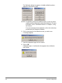
4. Open the Diagnostic Software.
5. Click on Calibrate in the Diagnostics dialog box.
A-61159 May 2002
4-17
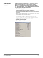
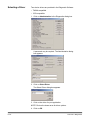
The Calibration dialog box appears. Available calibration options
depend on the scanner model.
NOTES: The Multifeed Thickness calibration option is used only when
enabling multifeed detection by document thickness. For more
information, refer to “Multifeed Detection” in this chapter.
For more information about calibration, refer to the online help
provided with the Diagnostic Software.
6. Click on the button for the calibration mode you wish to use.
A message appears.
7. Insert the calibration target into the scanner.
8. Click on OK.
Calibration begins. A confirmation box appears when calibration
has finished.
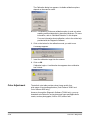
Color Adjustment
The default color table provides robust image quality for a
wide range of input and applications (Color Scanner 3590C and
Color Scanner 4500 only).
However, through the Diagnostic Software (TWAIN only), you may
download color tables for varying document types and applications
needs, such as photographs, text for OCR, and so forth.
4-18
A-61159 May 2002
5 Maintenance
Expected Life
of CustomerReplaceable
Wear Parts
• Kodak Digital Science Feed Module 150 (150-sheet automatic
paper feeder): 600,000 - 1,000,000 document pages
• Kodak Digital Science Feed Module 250 (250-sheet automatic
paper feeder): 600,000 - 1,000,000 document pages
• Kodak Digital Science Separator Roller: 300,000 - 600,000
document pages
• Kodak Digital Science White Imaging Lamp: up to 500 hours
• Kodak Digital Science Red, Green, and Blue Imaging Elements:
up to 300 hours
NOTES: The composition of the roller materials was engineered to
provide the ultimate in feeding reliability across the broadest
range of document types, sizes, and thicknesses. Expected
life figures are offered as guidelines for operations that follow
the recommended scanner cleaning procedures in this chapter
and that scan document types within the recommended
paper types (refer to “Preparing Documents for Scanning” in
Chapter 1, General Information).
Your experience may vary. Certain paper types (such as
carbonless paper), failure to clean regularly, and/or use
of non-recommended cleaning solvents can shorten roller life.
The inside of the scanner and certain replacement parts
shown in this chapter may appear different from the ones you
have. However, the actions described in the procedures are
the same.
To order additional cleaning supplies or replacement parts,
refer to Appendix B, Supplies.
A-61159 May 2002
5-1
Lowering the Pod
1. Power down the scanner.
2. Disconnect the power cord.
3. Remove the output tray.
5-2
A-61159 May 2002
4. Remove any documents from the feeder area.
5. Move the scanner forward to the front edge of the work surface.
6. Grasp the pod with one hand.
7. Pull the release latch with the other hand.
8. Gently lower the pod.
NOTE: The pod does not have to be lowered completely in order to
clear a document jam (refer to “Clearing Document Jams” in
Chapter 7, Troubleshooting).
Closing the Pod
A-61159 May 2002
• Close the pod by lifting the front of the pod until it snaps into place.
5-3
Feed Module
Cleaning the
Feed Module
For best scanner performance, clean the feed module rollers at least
once per week using the recommended Cleaning Pad (CAT No. 8535981). Use of any other cleaning materials could damage your scanner.
NOTE: Clean the rollers daily if you are scanning carbonless paper
or if you are using the document printer (Scanner 3520DP
or Color Scanner 4500DP only).
1. Follow all of the steps in “Lowering the Pod” in this chapter.
NOTE: You do not have to lower the pod completely to remove the
feed module.
2. Remove the feed module by pushing it to the right and lifting it out.
3. Wipe the rollers with a cleaning pad until all residue is removed.
4. Inspect the rollers.
If the rollers show signs of wear or damage, replace them.
5. Replace the feed module by aligning the pins and fitting it
into position.
6. Close the pod firmly.
5-4
A-61159 May 2002
Replacing the
Feed Module
Roller Tires
1. Follow all of the steps in “Lowering the Pod” in this chapter.
2. Remove the feed module by pushing it to the right and lifting it out.
3. Place the feed module on a flat surface with the side tabs up.
4. Press the locking tabs (one on each side) and pull the upper
housing up and away from the rollers.
5. Remove one core assembly.
6. Replace each tire by sliding the tire off the core.
A-61159 May 2002
5-5
7. Install each new tire by gently stretching it over the core.
IMPORTANT: Disregard the arrow on the side of the tire. It makes no
difference in which direction the arrows point.
Do not overstretch the tire; it may tear.
Make sure that the tire is centered on the core and is
lying flat on the core.
8. Replace the core assembly in the feed module (align the gears).
9. Repeat Steps 5 - 8 for the other core assembly.
5-6
A-61159 May 2002
10. Align the rear tabs on the lower housing with the rear tabs on the
upper housing.
11. Press the upper and lower housings together until they snap
into place.
12. Replace the feed module by aligning the pins and fitting it
into position.
13. Close the scanner pod.
A-61159 May 2002
5-7
Separator Rollers
Cleaning the
Separator Roller
For best scanner performance, clean the separator roller at least once
per week using the recommended Cleaning Pad (CAT No. 853-5981).
Use of any other cleaning materials could damage your scanner.
NOTE: Clean the rollers daily if you are scanning carbonless paper
or if you are using the document printer (Scanner 3520DP
or Color Scanner 4500DP only).
1. Follow all of the steps in “Lowering the Pod” in this chapter.
2. Open the separator roller access cover.
3. Remove the separator roller by pushing it to the right and lifting
it out.
5-8
A-61159 May 2002
4. Wipe the separator roller with a cleaning pad until all residue has
been removed.
5. Inspect the roller.
If the roller show signs of wear or damage, replace it.
6. Replace the separator roller by aligning the pins and fitting it
into position.
7. Close the access cover.
8. Close the pod firmly.
Replacing the
Separator Roller Tires
1. Follow all of the steps in “Lowering the Pod” in this chapter.
2. Open the separator roller access cover.
3. Remove the separator roller by pushing it to the right and lifting
it out.
4. Replace each tire by sliding the tire off the core.
A-61159 May 2002
5-9
5. Install each new tire by gently stretching it over the core.
IMPORTANT: Disregard the arrow on the side of the tire. It makes
no difference in which direction the arrows point.
Do not overstretch the tire; it may tear.
Make sure that the tire is centered on the core and
is lying flat on the core.
6. Insert the separator roller by aligning the pins in the
grooved brackets.
7. Close the separator roller access cover.
8. Close the scanner pod.
5-10
A-61159 May 2002
Drive Rollers
Cleaning the
Drive Rollers
For best scanner performance, clean the drive rollers at least once per
week using the recommended Cleaning Pad (CAT No. 853-5981). Use
of any other cleaning materials could damage your scanner.
NOTE: Clean the rollers daily if you are scanning carbonless paper
or if you are using the document printer (Scanner 3520DP
or Color Scanner 4500DP only).
1. Follow all of the steps in “Lowering the Pod” in this chapter.
2. Remove the feed module by pushing it to the right and lifting it out.
3. Open the side access door.
A-61159 May 2002
5-11
4. Wipe the drive rollers with a cleaning pad until all residue has
been removed.
5. Clean any dust or debris in the slots around the drive rollers.
6. Close the side access door.
7. Replace the feed module by aligning the pins and fitting it
into position.
8. Close the pod firmly.
5-12
A-61159 May 2002
Imaging Guides
Cleaning the
Imaging Guides
For best image quality, clean both imaging guides at least once per day
(or more often if necessary) using the recommended Staticide Wipe
(CAT No. 896-5519). Use of any other cleaning materials could damage
your scanner.
NOTES: Clean the imaging guides daily if you are scanning
carbonless paper or if you are using the document printer
(Scanner 3520DP or Color Scanner 4500DP only).
During cleaning, avoid getting fingerprints on the
imaging guides.
1. Follow all of the steps in “Lowering the Pod” in this chapter.
2. Open the side access door.
3. Grasp the end of the imaging guide that is behind the side access
door and slowly pull it straight out.
A-61159 May 2002
5-13
4. Wipe the imaging guide with a Staticide Wipe until all residue has
been removed.
If streaking occurs, allow the wipe to partially dry and re-clean the
imaging guide.
5. Replace the imaging guide.
Make sure it is fully seated in its slot.
6. Grasp the end of the imaging guide that is in the pod and slowly pull
it straight out.
7. Wipe the imaging guide with a Staticide Wipe until all residue has
been removed.
8. Replace the imaging guide in the pod.
Make sure it is fully seated in its slot.
9. Close the side access door.
10. Close the pod firmly.
5-14
A-61159 May 2002
Replacing the
Imaging Guides
1. Follow all of the steps in “Lowering the Pod” in this chapter.
2. Open the side access door.
3. Grasp the end of the imaging guide that is behind the side access
door and slowly pull it straight out.
4. Replace the imaging guide.
Make sure it is fully seated in the slot.
A-61159 May 2002
5-15
5. Grasp the end of the imaging guide that is in the pod and slowly pull
it straight out.
6. Replace the imaging guide in the pod.
Make sure it is fully seated in the slot.
7. Close the side access door.
8. Close the pod firmly.
5-16
A-61159 May 2002
Paper Path and
Sensors
Cleaning the Paper Path
For best scanner performance, clean the paper path at least once per
week using the recommended Transport Cleaning Sheet (CAT No. 1690783). Use of any other cleaning materials could damage your scanner.
NOTE: Clean the paper path daily if you are scanning carbonless paper
or if you are using the document printer (Scanner 3520DP or
Color Scanner 4500DP only).
1. Remove the wrapping from the Transport Cleaning Sheet.
2. Adjust the paper feeder guides to fit the cleaning sheet.
A-61159 May 2002
5-17
3. Feed the cleaning sheet (adhesive side up) twice through the
scanner in portrait orientation.
4. Adjust the feeder guides to fit, then feed the cleaning
sheet (adhesive side up) twice through the scanner in
landscape orientation.
5. Using the same cleaning sheet, repeat Steps 2 and 3, but feed the
cleaning sheet through the scanner with the adhesive side down.
NOTE: When a cleaning sheet gets very dirty, discard it and use a
new one.
5-18
A-61159 May 2002
Cleaning the Sensors
For best scanner performance, clean the sensors at least once per
week using a clean, dry, lint-free cloth or a camel hair brush. Use of any
other cleaning materials could damage your scanner.
NOTE: Clean the sensors daily if you are scanning carbonless paper
or if you are using the document printer (Scanner 3520DP
or Color Scanner 4500DP only).
1. Follow all of the steps in “Lowering the Pod” in this chapter.
2. Remove the feed module by pushing it to the right and lifting it out.
3. Wipe the sensors with a clean, dry, lint-free cloth or camel
hair brush.
4. Wipe the sensor reflective strips directly opposite each sensor.
5. Replace the feed module by aligning the pins and fitting it
into position.
6. Close the pod firmly.
A-61159 May 2002
5-19
Cleaning the
Transport Baffles
Clean the baffles daily if you are scanning carbonless
paper or if you are using the document printer (Scanner 3520DP
or Color Scanner 4500DP only).
1. Follow all of the steps in “Lowering the Pod” in this chapter.
2. Wipe the transport baffles with a roller cleaning pad.
3. Dry the transport baffles with a lint-free cloth.
4. Close the pod firmly.
5-20
A-61159 May 2002
Lamps
The scanner has a lamp saver feature to prolong lamp life. The lamps
shut off after 10 minutes of scanner idle time. Do not mistakenly replace
lamps that are off due to the lamp saver mode.
IMPORTANT: If you disable the lamp saver feature, your lamps will
wear out more quickly.
Replacing Lamps
There are two identical lamps in the scanner. The procedure below
shows how to replace the lamp behind the side access door. Use the
same procedure to replace the lamp in the pod.
NOTE: To order lamps, refer to Appendix B, Supplies.
CAUTION:Lamps that have been operating are HOT. Make sure
that the lamp has cooled before you replace it.
1. Follow all of the steps in “Lowering the Pod” in this chapter.
2. Open the side access door.
CAUTION:Make sure that the scanner is turned off, and allow
it to cool for 10 minutes before attempting to replace
the lamp.
A-61159 May 2002
5-21
3. Remove the imaging guide.
4. Grasp the green handle of the lamp connector.
5. Slightly raise the edge of the black holder and remove the
lamp connector.
5-22
A-61159 May 2002
6. Grasp the end of the lamp and slowly pull the lamp straight out.
7. Position the new lamp in the lamp holder.
IMPORTANT: Make sure that the clear surface of the lamp is positioned
facing the imaging guide.
Use a slight downward pressure as you push the lamp into the
scanner. This will help the lamp slide in easily.
8. Push firmly on the end of the lamp to seat the lamp into the
connector on the other end.
9. Replace the lamp connector and push in firmly so that the connector
is fully seated.
10. Replace the imaging guide.
11. Close the side access door.
12. Close the pod firmly.
A-61159 May 2002
5-23
6 Diagnostics
Introduction
The host diagnostic software described in this section refers to the
Kodak Digital Science Diagnostic Software. Integrator-supplied
software will be different.
The Diagnostic Software is an easy-to-use tool for setting up, testing,
updating, and troubleshooting your scanner. A password feature allows
the system administrator to provide or restrict access to functions in the
Diagnostic Software.
The Diagnostic Software is installed on your PC during the initial
scanner setup process and can be used by scanner operators and
system administrators.
IMPORTANT: If you are installing the Diagnostic Software in
Windows 95, Microsoft Internet Explorer v4.0 or
greater must be installed on the computer.
The Diagnostic Software allows functions (some may be password
protected) such as:
• selecting scanner settings
• selecting a device driver
• performing tests and calibration
• capturing an image
• viewing the error log and service log
The Diagnostic Software also allows certain administrative functions,
such as:
• setting password protection
• downloading firmware
• changing the user registry
NOTE:For more information about the Diagnostic Software features,
refer to the online help in the software.
A-61159 May 2002
6-1
Testing the System
Two brief tests can be run to check scanner performance: self-test and
scan system test.
• A self-test checks the image processing hardware in the scanner.
• A scan system test checks the scanner’s ability to capture an image.
In order to perform a self-test or scan system test, the Diagnostic
Software must be installed on your PC.
Performing a Self-Test
6-2
• Click on Self-test in the Diagnostics dialog box.
A-61159 May 2002
Testing the Scan System
1. Click on Setup and Test in the Diagnostics dialog box.
The Setup and Test dialog box appears.
2. Place a document into the feeder area.
3. Click on Scan One Page.
The document should be scanned.
A-61159 May 2002
6-3
Downloading the
Date and Time
If you wish, you can set the scanner’s date and time to the host
computer’s date and time.
1. Click on Administration in the Diagnostics dialog box.
A password may be required. The Administration dialog
box appears.
2. Click on Download Host Date/Time.
The date and time are downloaded. A confirmation box appears.
6-4
A-61159 May 2002
Calibrating the
Scanner
Calibration optimizes the optical system in your scanner in order to
achieve the best overall quality of scanned images. Frequent
calibration is not needed or recommended. When you do calibrate
(e.g., after changing a lamp), be sure the lamps have been on for at
least three minutes, then follow this procedure:
1. Clean both imaging guides.
Refer to “Imaging Guides” in Chapter 5, Maintenance.
2. Wait three minutes after the pod has been closed to allow the lamps
to warm up.
3. Obtain a proper calibration target—use a clean, blank, white sheet
of paper with a matte surface (not glossy).
Make sure that the target is wider than the documents to be
scanned. It is best to use the 30.5 cm (12 in.) square calibration
target available from Kodak (Cat. No. 127-1436).
4. Open the Diagnostic Software.
5. Click on Calibrate in the Diagnostics dialog box.
A-61159 May 2002
6-5
The Calibration dialog box appears. Available calibration options
depend on the scanner model.
NOTES: The Multifeed Thickness calibration option is used only when
enabling multifeed detection by document thickness. For more
information, refer to “Multifeed Detection” in Chapter 4, Using
the Scanner.
For more information about calibration, refer to the online help
provided with the Diagnostic Software.
6. Click on the button for the calibration mode you wish to use.
A message appears.
7. Insert the calibration target into the scanner.
8. Click on OK.
Calibration begins. A confirmation box appears when calibration
has finished.
6-6
A-61159 May 2002
Downloading
Firmware
Firmware is the scanner’s internal software. It is possible to download a
firmware file to the scanner.
1. Click on Administration in the Diagnostics dialog box.
A password may be required. The Administration dialog
box appears.
2. Click on Download File.
3. Click on the firmware file (.ekfw extension) that you want
to download.
4. Click on Open.
The firmware file is downloaded.
A-61159 May 2002
6-7
Error Log
The error log in the Diagnostic Software contains information about any
errors that have occurred during scanner operations.
• Click on Error Log in the Diagnostics dialog box.
The current error log (if any) appears.
6-8
A-61159 May 2002
Service Log
The service log in the Diagnostic Software allows you to log any
repairs, parts replacement, or maintenance performed on the scanner.
1. Click on Administration in the Diagnostics dialog box.
A password may be required. The Administration dialog
box appears.
2. Click on Service Log.
The current service log (if any) appears.
A-61159 May 2002
6-9
Selecting a Driver
Two device drivers are provided in the Diagnostic Software:
• TWAIN-compatible
• ISIS-compatible
1. Click on Administration in the Diagnostics dialog box.
A password may be required. The Administration dialog
box appears.
2. Click on Select Driver.
The Select Driver dialog box appears.
3. Click on the driver for your application.
NOTE:Click on the down arrow for driver options.
4. Click on OK.
6-10
A-61159 May 2002
7 Troubleshooting
Indicator Lights
There are four indicator lights on the front of the scanner.
Power
Ready
Jam
Error
On
Off
Flashing.
Power Electrical power
(Green) is on (normal
operation)
Electrical power
is off
Scanner is in
lamp saver or
diagnostic mode
Ready Scanner is ready
(Green) to scan (normal
operation)
Scanner is
not currently
scanning, or
is not ready to
scan due to
various hardware
or software
conditions
Scanner is
powering up
or is in lamp
warm-up or
calibration mode
Jam
Not a valid state
(Yellow)
No paper jams are Sensor failure
being detected
or paper jam
(normal operation) during scanning
Error
(Red)
A failure or
a document
multifeed has
occurred
No errors are
An error
being detected
has occurred
(normal operation)
NOTE: If the red light is on or flashing, check the error log in the
Diagnostic Software.
A-61159 May 2002
7-1
Clearing
Document Jams
1. Remove any documents from the feeder.
2. Lower the pod slightly and open the side access door.
CAUTION:The lamps are HOT. Avoid contact with the hot lamps.
3. Locate the jammed document and remove it.
NOTE: Avoid getting fingerprints on the imaging guides.
4. Close the side access door.
5. Close the pod firmly.
Some jams can be cleared without opening the side access door.
To clear a document jam from the front of the scanner, lower the pod
slightly, remove the document, and close the pod firmly.
For greater access to the area, you can remove the feed module (refer
to “Feed Module” in Chapter 5, Maintenance).
7-2
A-61159 May 2002
Color Image Quality
Color image quality is highly subjective because people perceive color
images differently. Here are some things to consider when scanning
in color:
• The differing color outputs of scanners, printers, and monitors can
affect the perception of the scanned document.
• Computer monitor displays and printer output can vary from
model to model, and from manufacturer to manufacturer. An image
may be acceptable on one monitor and unacceptable on another.
• Area lighting (fluorescent, natural, incandescent) can affect
color perception.
• The appearance of a colored area within an image can be perceived
differently, based on what surrounds it.
• The characteristics and condition of a document can have an impact
on color consistency.
• Color requirements may differ between environments (e.g., in a
business document environment, images are generally viewed on a
monitor, whereas in a “print on demand” environment, scanned
images are printed).
To ensure that your scanner is delivering the best image:
• Clean the scanner. Contamination within the scanner
degrades image quality. (Refer to Chapter 5, Maintenance,
for cleaning information.)
• Calibrate the scanner at least once per week.
• Make sure that the calibration target is clean and unwrinkled.
• Change the color table. Individual results may vary.
The default color table provides robust image quality for a wide
range of input and applications. However, additional specialized color
tables are available from within the Diagnostic Software (for TWAIN
only) for varying document types and applications needs, such as
photographs, text for OCR, and so forth.
NOTES: Calibrate the scanner before you change the color table.
Color scanning is available only on the Color Scanner 3590C
and Color Scanner 4500.
A-61159 May 2002
7-3
Error Log
The error log in the Diagnostic Software contains information
about any errors that have occurred during scanner operations.
For more information about the error log, refer to “Error Log” in
Chapter 6, Diagnostics.
NOTE: For more information about the Diagnostic Software features,
refer to the online help in the software.
Testing the System
Two brief tests can be run to check scanner performance: self-test and
scan system test.
• A self-test checks the image processing hardware in your scanner.
• A scan system test checks the scanner’s ability to capture an image.
For more information about these tests, refer to “Testing the System” in
Chapter 6, Diagnostics.
NOTE: In order to perform a self-test or scan system test, the
Diagnostic Software must be installed on your PC.
Service Information
If you are having a problem with your scanner, first perform the
appropriate tasks in this chapter or in Chapter 5, Maintenance, or
Chapter 6, Diagnostics. The section “Problem Solving” in this chapter
has a chart that may be useful in diagnosing problems.
If the problem persists and you believe that your scanner needs
service, contact your reseller directly. Your reseller will arrange
for service.
7-4
A-61159 May 2002
Moving the Scanner
If it becomes necessary to move the scanner after installation, you must
repack the scanner using the original packaging materials.
If you do not have the original packaging materials, contact your
supplier to order a Scanner Relocation Kit (CAT No. 825-6083).
To repack the scanner:
1. Power down the computer.
2. Turn off the scanner.
3. Disconnect the power cord from the back of the scanner.
A-61159 May 2002
7-5
4. Disconnect the SCSI-2 cable from the back of the scanner.
5. Remove the output tray and set it aside for now.
6. Using two people, lift the scanner and place it in the foam base that
is inside the box.
7. Place the power cord in the box.
8. Cover the scanner with the bag.
7-6
A-61159 May 2002
9. Place the foam cover on top of the scanner.
10. Place the output tray on top of the foam cover.
11. Close the box.
The scanner is now ready for moving.
A-61159 May 2002
7-7
Problem Solving
Problem
Occasionally, you may experience a problem with your scanner.
In many cases, you can easily fix the problem yourself. Try the
solutions in the order in which they appear. To perform suggested
maintenance or diagnostic tasks, refer to Chapter 5, Maintenance,
or Chapter 6, Diagnostics.
Possible Solution
The scanner will not scan/
feed documents
Make sure that:
• the power cord is plugged in and the power is on.
• the side access door and pod are completely closed.
• the printer access door (Scanner 3520DP or Color Scanner
4500DP) is completely closed.
• the proper power-up sequence was followed and the software has
enabled scanning.
• the top green indicator light on the front panel is on.
• documents are making contact with the feed module.
• the height of batched documents is less than:
15.2 mm (0.6 in.) on a scanner using the Feed Module 150.
25.3 mm (1.0 in.) on a scanner using the Feed Module 250.
• for documents stacked near the maximum heights listed above, you
position the batch 12.7 mm (0.5 in.) away from the baffle housing.
• documents meet specifications for size, weight, and height of
batched documents, etc.
• for thicker documents, you press the gap release button
during feeding.
• you check the feed module and separator roller for signs of wear,
and replace these parts if necessary.
• you try to scan a document using the Diagnostic Software.
Image quality is poor or
has decreased
Make sure that:
• the lamps have been on at least three minutes.
• the scanner is calibrated (refer to “Calibrating the Scanner” in
Chapter 6, Diagnostics).
• the imaging guides are clean (refer to “Imaging Guides” in Chapter
5, Maintenance).
• you use the Diagnostic Software to scan a document using different
settings to see if image quality improves.
If unsatisfactory image quality persists, or if the scanner fails
calibration, replace the lamps (refer to “Lamps” in Chapter 5,
Maintenance). Be sure to calibrate the scanner after installing the
new lamps. Make sure that the new lamps have been on at least
three minutes before you calibrate.
7-8
A-61159 May 2002
Problem
Possible Solution
The first few scanned
images are very dark
Make sure that the lamps have been on for at least 30 seconds, then
scan the images again.
Both green indicator
lights on the front panel
are flashing
The 48-megabyte image buffer is full. Stop scanning momentarily and
wait for the host computer to “catch up” with the scanner output. This
will free up space in the image buffer. Make sure that there are no
problems with your scanning software.
The amber indicator light on Most likely, a document jam has occurred in the paper transport area.
the front panel is flashing
Refer to “Clearing Document Jams” in this chapter.
The red indicator light
on the front panel is on
or flashing
If the red indicator is on, a failure (power-up, lamp, hardware,
software, accessory, calibration, or multifeed) has occurred.
If the red indicator is flashing, an error (for example, a lost or
corrupted image) has occurred.
Refer to “Error Log” in this chapter, then access the Diagnostic
Software and check the error log for information.
Refer to the appropriate chapter (Chapter 5, Maintenance, Chapter 6,
Diagnostics, and/or Chapter 7, Troubleshooting) to correct the
problem identified in the error log.
Calibration has failed
Make sure that:
• the lamps have been on at least three minutes.
• you are using a proper calibration target. Use a clean, blank sheet
of white paper with a matte surface (not glossy). The calibration
target should be wider than the documents you are scanning. It is
best to use the 30.5 cm (12 in.) square calibration target available
from Kodak. You may use a different target if it meets the conditions
above, but the target must be at least 20 cm (8 in.) in length.
• the imaging guides are clean (refer to “Imaging Guides” in
Chapter 5, Maintenance).
• the transport area is clear of obstructions.
Try calibration again. If calibration fails again, replace the lamps (refer
to “Lamps” in Chapter 5, Maintenance). Be sure to calibrate the
scanner after installing the new lamps. Make sure the new lamps have
been on at least three minutes before you calibrate. If calibration still
fails, request assistance.
“False” paper jams
are occurring
If the amber indicator light on the front panel is flashing, and no paper
is jammed inside the scanner, make sure that the paper transport
sensors are clean (refer to “Paper Path and Sensors” in Chapter 5,
Maintenance). Very dirty sensors can cause a false paper jam to
be indicated.
A-61159 May 2002
7-9
Problem
Possible Solution
Documents are jamming
Make sure that:
• the output tray and guides are adjusted for the length of documents
being scanned.
• all jammed documents have been removed from the paper
transport area.
• documents meet specifications for size, weight, and height of
batched documents, etc.
• the sensors, and the reflective tape opposite the sensors, are clean.
• the separator roller access cover is properly seated.
• the separator roller and feed module are clean and
properly installed.
• the paper transport rollers are clean.
• the imaging guides behind the side access door are
properly installed.
Documents are skewed
during scanning
Make sure that:
• the feeder guides are adjusted to fit the documents being fed.
• documents are being fed perpendicular to the feed module.
• documents are being fed in the center of the feeder, with the full
width of the feeder rollers making contact with all documents.
• the feed module, separator roller, and paper transport rollers
are clean.
35.6 cm (14 in.) or longer
documents are not feeding
or are jamming
Make sure that:
• the input tray extender is opened to provide support for
long documents.
• the output tray is adjusted for the length of the documents
being scanned.
• the output tray is installed properly under the scanner. The output
tray’s center rib must be located in the center slot under the scanner
so that you can easily slide the tray in or out.
Documents are multifeeding Make sure that:
• the leading edges of all batched documents are centered under the
automatic paper feeder so that each document comes in contact
with the feeder rollers.
• the feed module and separator roller are clean and not worn.
• documents with an unusual texture or surface are fed manually.
7-10
A-61159 May 2002
Problem
Possible Solution
There are frequent multifeed Make sure that:
detection errors
• multifeed thickness has been calibrated.
• the pod and side access door are completely closed.
The output tray cannot be
adjusted in or out
Make sure the output tray is installed properly under the scanner.
The output tray’s center rib must be located in the center slot under
the scanner so that you can easily slide the tray in or out.
Roller marks appear on
documents after scanning
Clean the feed module rollers, separator roller, and drive rollers.
Refer to Chapter 5, Maintenance.
The first few color images
are very bright
Make sure that the lamps have been on at least three minutes, then
scan the images again.
On the Color Scanner
3590C, the back side of
documents does not
appear in color
This is normal. Color scanning on the Color Scanner 3590C is for the
front side of documents only.
On the Color Scanner
3590C, the patch document
is not detected; therefore,
the scan mode does not
change between color and
bitonal (black and white)
Make sure that:
• patch detection is enabled in your software.
• the patch document meets specifications.
A-61159 May 2002
For more information, refer to “Switching Scan Modes” in Chapter 4,
Using the Scanner.
7-11
Appendix A Specifications
Scanner Type
Scanner 3500: Bitonal simplex/duplex scanner with ADF
Scanner 3510: Bitonal simplex/duplex scanner with ADF
Scanner 3520: Bitonal simplex/duplex scanner with ADF;
optional document printer
Color Scanner 3590C:Color and bitonal simplex/duplex scanner with ADF
Color Scanner 4500: Color simplex/duplex scanner with ADF;
optional document printer
Image Capture
Resolution
Scanner 3500: 600 dpi bitonal scanners
Scanner 3510: 600 dpi bitonal scanners
Scanner 3520: 600 dpi bitonal scanners
Color Scanner 3590C:600 dpi bitonal/150 dpi color
Color Scanner 4500: 150 dpi color
Image Output
Resolution
Scanner 3500: 200 and 300 dpi bitonal
Scanner 3510: 200 and 300 dpi bitonal
Scanner 3520: 200 and 300 dpi bitonal
Color Scanner 3590C:200 and 300 dpi bitonal/100 and 150 dpi color
Color Scanner 4500: 100 and 150 dpi color
Scan Area
Length: 6.4 to 43.2 cm (2.5 to 17 in.)
Width: 8.9 to 30.5 cm (3.5 to 12 in.)
NOTE:A page fed into the scanner can be up to 30.5 cm (12 in.) wide, but the
maximum image width that is captured is 29.7 cm (11.7 in.).
Electrical
Requirements
Scanner 3500, Scanner 3510, and Scanner 3520:
100-127V AC 50/60 Hz, 1 phase
200-240V AC 50/60 Hz, 1 phase
Color Scanner 3590C and Color Scanner 4500:
100-130V AC 50/60 Hz, 1 phase
210-240V AC 50/60 Hz, 1 phase
Dimensions
Height: 31.8 cm (12.5 in.)
Width: 53.5 cm (21.0 in.)
Depth: 70.0 cm (27.5 in.)
Weight
Scanner 3500, Scanner 3510, and Scanner 3520: 31.8 kg (70 lb.)
Color Scanner 3590C and Color Scanner 4500: 34 kg (75 lb.)
A-61159 May 2002
A-1
Host Connection
Interface: SCSI-2
Two SCSI-2, 50-pin, high-density D-Shell connectors are provided on the rear
panel for SCSI connectivity.
A switch on the rear panel allows you to select the scanner’s SCSI ID number.
Operating
Temperature
15 to 35°C (59-95°F)
Humidity
15 to 76% (dry bulb)
Altitude
Up to 2440 m (8000 ft)
Acoustic Noise
Data was measured in accordance with DIN 45 635, ANSI S12.10-1985, and
ISO 7779 in a hemi-anechoic chamber.
Scanner 3500, Scanner 3510, and Scanner 3520:
• Operator position sound pressure levels (LpA)
- Standby: 55.0 dB(A)
- Full system: 64.0 dB(A)
- Instantaneous peak values t 130 dB(C): None
• Sound power levels (LwA)
- Standby: 62.0 dB(A)
- Full system: 70.0 dB(A)
Color Scanner 3590C and Color Scanner 4500:
• Operator position sound pressure levels (LpA)
- Standby: 49.1 dB(A)
- Full system: 62.4 dB(A)
- Instantaneous peak values t 130 dB(C): None
• Sound power levels (LwA)
- Standby: 60.4 dB(A)
- Full system: 70.0 dB(A)
Specification values apply to all of the Scanner 3000/4000 Series
except where noted. All of these specifications are subject to change
without notice.
A-2
A-61159 May 2002
Appendix B Supplies
Contact your scanner supplier to order supplies such as
lamps, cleaning materials, and replacement parts.
To order consumables, visit us online at
http://www.kodak.com/go/shop
Item
CAT No.
Lamps/Imaging Elements
Kodak Digital Science White Imaging Lamp for Series 3000 Scanners
876-6545
Kodak Digital Science Red Imaging Element, 3000/5000/7000 (2)
126-0884
Kodak Digital Science Green Imaging Element, 3000/5000/7000 (2)
132-9812
Kodak Digital Science Blue Imaging Element, 3000/5000/7000 (2)
800-1307
Replacement Parts
Kodak Digital Science Imaging Guide for Series 3000 Scanners
806-6318
Kodak Digital Science Front Imaging Guide for Color Scanner 3590C
156-9664
Kodak Digital Science Feed Module 150 (Scanner 3500, Color Scanner 3590C)
153-7240
Kodak Digital Science Feed Module 250 (Scanner 3510/3520, Color Scanner 4500)
159-2195
Kodak Digital Science Separator Roller for Series 3000/4000 Scanners
828-0604
KODAK Separator Roller, Type 2, for Series 3000/4000 Scanners
158-8052
Kodak Digital Science Output Tray (Scanner 3500 and Color Scanner 3590C)
181-6826
Kodak Digital Science Enhanced Output Tray (Scanner 3510/3520, Color Scanner 4500)
876-7485
Kodak Digital Science Output Deflector for Series 3000/4000 Scanners
858-3858
Kodak Digital Science Imaging Guide for 4000 Scanners
825-0698
Recommended Calibration Target
Kodak Digital Science Calibration Target for Kodak Scanners (5)
127-1436
Maintenance Kit
Kodak Digital Science Consumables Kit for Series 3000 Scanners
(includes Imaging Guides [2], Feed Module 150, Separator Roller,
White Imaging Lamps [2], Transport Cleaning Sheets, Roller Cleaning Pads,
Staticide Wipes, and a Calibration Target)
854-6012
Upgrade Kit
Kodak Digital Science Feed Module 250 and Enhanced Output Tray Upgrade Kit
(to upgrade the Scanner 3500 and Color Scanner 3590C)
A-61159 May 2002
843-1686
B-1
Item
CAT No.
Cleaning Supplies
Kodak Digital Science Transport Cleaning Sheets (50)
169-0783
Kodak Digital Science Roller Cleaning Pads (24)
853-5981
Staticide Wipes for Kodak Scanners (144)
896-5519
Document Printer Supplies
Kodak Digital Science Printer Ink Blotters for Series 3000 / 4000 Scanners
(24 [12 short, 12 long])
839-4306
Kodak Digital Science Printer Ink Cartridge Carrier for Series 3000 / 4000 Scanners
838-4885
Replacement Packing Materials
Kodak Digital Science Relocation Kit for Series 3000 Scanners
B-2
825-6083
A-61159 May 2002
Index
A
Access door, printer, 3-6
Acoustic noise, scanner, A-2
Agency approvals, 1-3
Alarm volume, setting for multifeed, 4-10, 4-11,
4-12, 4-14
Altitude for scanner operation, A-2
Approvals
agency, 1-3
regulatory, 1-3
safety, 1-3
ASCII character set, printable, 3-1
Attaching output tray, 2-4
Automatic feeding, scanning, 4-2
B
Baffles, cleaning, 5-20
Batch height, maximum for automatic
feeding, 1-10
Black-and-white to color scanning, 4-6 to 4-9
Blue imaging element, expected life of, 5-1
Box, saving, 2-1
Bright color images, 7-11
Business cards, scanning, 4-5
C
Calibrating scanner, 4-17 to 4-18, 6-5 to 6-6
Calibration, 6-1
failed, 7-9
mode, 7-1
multifeed thickness, 4-14, 4-18, 6-6
options, 4-18, 6-6
target, 4-17, 6-5
replacement, ordering, B-1
Capacity
paper transport, 1-8
Color Scanner 3590C, 1-8
Color Scanner 4500, 1-8
Scanner 3500, 1-8
Scanner 3510, 1-8
Scanner 3520, 1-8
Capturing image, 6-1
Catalog numbers, B-1 to B-2
A-61159 May 2002
consumables, B-1 to B-2
parts, B-1 to B-2
supplies, B-1 to B-2
Changing
print string, 3-3
user registry, 6-1
Character font
resolution, 3-2
size, 3-2
Characters, printer, 3-2
Cine
character font, 3-2, 3-3
resolution, 3-2
size, 3-2
printer font, 3-5
Cleaning
baffles, 5-20
drive rollers, 5-11 to 5-12
feed module, 5-4
imaging guides, 5-13 to 5-14
paper path, 5-17 to 5-18
sensors, 5-19
separator roller, 5-8 to 5-9
transport baffles, 5-20
Cleaning supplies, replacement, ordering, B-2
Clearing document jams, 7-2
Closing pod, 5-3
Color
adjustment, 4-18, 7-3
images
adjusting color, 4-18, 7-3
bright, 7-11
quality, 4-18, 7-3
scanning, 7-11
tables, 4-18, 7-3
Color Scanner 3590C
switching scan modes, 4-6 to 4-9
throughput, 1-8
using patch document to switch scan
modes, 4-6 to 4-9
Color Scanner 4500 throughput, 1-8
Color tables, 4-18, 7-3
Color to black-and-white scanning, 4-6 to 4-9
Index-1
Comic
character font, 3-2, 3-3
resolution, 3-2
size, 3-2
printer font, 3-5
Components
document printer, expected life of, 3-11
scanner, 1-11
external, 1-11
internal, 1-11
rear, 1-11
Configurations, standard, 1-7
Connecting SCSI cable, 2-3
Consumables
catalog numbers, B-1 to B-2
ordering, B-1 to B-2
Continuous feeding, scanning, 4-3
Correction fluids, acceptable, 1-10
Counter
Printer tab option, Diagnostic Software, 3-5
Counter Format
Display Leading Zeroes, 3-5
Printer tab option, Diagnostic Software, 3-5
Suppress Leading Zeroes, 3-5
Curled documents, 2-5
D
Damaged documents, scanning, 4-4 to 4-5
Dark images, 7-9
Date and time, downloading, 6-4
Date Delimiter
Printer tab option, Diagnostic Software, 3-5
Defaults
Printer tab option, Diagnostic Software, 3-5
Deflector, lowering, 2-5
Detecting multifeed
by length, 4-10, 4-12
by thickness, 4-12
Device driver, selecting, 6-1, 6-10
Diagnostic mode, 7-1
Diagnostic Software, 1-1, 1-5, 1-6, 1-7, 6-1 to 6-10
installing, 2-6
Printer tab
Counter, 3-5
Counter Format, 3-5
Date Delimiter, 3-5
Index-2
Defaults, 3-5
Enable, 3-4
Font, 3-5
Message, 3-5
options, 3-4 to 3-5
Printer Test, 3-5
String item selection list, 3-5
string text display box, 3-4
Y Offset, 3-5
Diagnostics, 6-1 to 6-10
Dimensions, scanner, A-1
Disabling
multifeed detection
for Color Scanner 3590C, 4-15 to 4-16
for Color Scanner 4500, 4-15 to 4-16
for Scanner 3500, 4-11
for Scanner 3510, 4-15 to 4-16
for Scanner 3520, 4-15 to 4-16
multifeed detection button, 4-15 to 4-16
patch detection, 4-9
same-size document scanning, 4-4
Display Leading Zeroes, Counter Format, 3-5
Document
batch height, maximum for automatic
feeding, 1-10
jams, clearing, 7-2
not feeding correctly, 7-8
not scanning correctly, 7-8
preparation, 1-9 to 1-10
acceptable document sizes, 1-10
acceptable document thicknesses, 1-10
acceptable materials, 1-9
acceptable paper correction fluids, 1-10
acceptable paper inks, 1-10
recommended paper types, 1-9
recommended paper weights, 1-9
sizes, acceptable, 1-10
skewed, 7-10
specifications, 1-9 to 1-10
acceptable document sizes, 1-10
acceptable document thicknesses, 1-10
acceptable materials, 1-9
acceptable paper correction fluids, 1-10
acceptable paper inks, 1-10
recommended paper types, 1-9
recommended paper weights, 1-9
A-61159 May 2002
thicknesses, acceptable, 1-10
Document printer, 3-1 to 3-16
characters, 3-2
components, expected life of, 3-11
dynamic information, 3-1, 3-2
ink blotter strips, replacing, 3-12 to 3-14
ink cartridge
installing, 3-8 to 3-9
purging, 3-7
replacing, 3-11
ink cartridge carrier, replacing, 3-15 to 3-16
maintenance, 3-11 to 3-16
minimum document width, 3-3
overview, 3-1 to 3-5
print positions, 3-3
setting, 3-10
setting up through Diagnostic Software, 3-4
specification
dynamic fields, 3-4
font size, 3-4
ink cartridge, 3-4
maximum lines, 3-4
minimum document width, 3-4
print locations, 3-4
print orientation, 3-4
print side, 3-4
static fields, 3-4
supported languages, 3-4
static information, 3-1, 3-2
Document printer supplies, replacement,
ordering, B-2
Document printing problems, 3-11
Download File, 6-7
Download Host Date/Time, 6-4
Downloading
date and time, 6-4
firmware, 6-1, 6-7
Drive rollers, 5-11 to 5-12
cleaning, 5-11 to 5-12
Dynamic fields, printer, 3-4
Dynamic information, printer, 3-1, 3-2
Dynamic print field options, 3-2 to 3-3
Control of the Printer, 3-2
Date, 3-2
Sequential Document Number, 3-2
Time, 3-2
A-61159 May 2002
E
Electrical requirements, A-1
Electromagnetic compliance statements, 1-4
EMC statements, 1-4
Enable
Printer tab option, Diagnostic Software, 3-4
Enabling
multifeed detection
for Color Scanner 3590C, 4-12 to 4-14
for Color Scanner 4500, 4-12 to 4-14
for Scanner 3500, 4-10 to 4-11
for Scanner 3510, 4-12 to 4-14
for Scanner 3520, 4-12 to 4-14
multifeed detection button, 4-13
patch detection, 4-8
same-size document scanning, 4-3
Enhanced output tray, ordering upgrade kit, B-1
Environmental information, 1-3
Error log, viewing, 6-1, 6-8, 7-4
Expected life
blue imaging element, 5-1
customer-replaceable wear parts, 5-1
Feed Module 150, 5-1
Feed Module 250, 5-1
green imaging element, 5-1
red imaging element, 5-1
separator roller, 5-1
white imaging lamp, 5-1
External scanner components, 1-11
F
Failure, scanner, 7-1
False paper jams, 7-9
Features
image quality, 1-6
bitonal scanners, 1-6
color scanners, 1-6
maintenance, 1-7
paper transport, 1-6
scanner, 1-5
troubleshooting, 1-7
Feed module, 5-4 to 5-7
cleaning, 5-4
tires, replacing, 5-5 to 5-7
Feed Module 150
expected life of, 5-1
Index-3
Feed Module 250, B-1
expected life of, 5-1
Feeder, specifications, 1-7
Firmware, downloading, 6-1, 6-7
Flashing indicator light, 4-1, 7-1, 7-9
Font
character, printer, 3-2
Printer tab option, Diagnostic Software, 3-5
resolution, 3-2
size, 3-2
Font size, printer, 3-4
G
General information, 1-1 to 1-11
Glass guides, 5-13 to 5-16
Green imaging element, expected life of, 5-1
Green indicator light, 7-1
H
Host connection, scanner, A-2
Host diagnostics software, 2-6, 6-1 to 6-10
Humidity for scanner operation, A-2
I
Image
bright, 7-11
capturing, 6-1
dark, 7-9
Image capture resolution, A-1
Image output resolution, A-1
Image quality
color, 4-18, 7-3
features, 1-6
bitonal scanners, 1-6
color scanners, 1-6
poor, 7-8
Imaging elements
replacement, ordering, B-1
Imaging guides, 5-13 to 5-16
cleaning, 5-13 to 5-14
replacing, 5-15 to 5-16
Imprinter, 3-1 to 3-16
characters, 3-2
components, expected life of, 3-11
dynamic information, 3-1, 3-2
Index-4
font
resolution, 3-2
size, 3-2
ink blotter strips, replacing, 3-12 to 3-14
ink cartridge
installing, 3-8 to 3-9
purging, 3-7
replacing, 3-11
ink cartridge carrier, replacing, 3-15 to 3-16
maintenance, 3-11 to 3-16
minimum document width, 3-3
overview, 3-1 to 3-5
print positions, 3-3, setting, 3-10
setting up, through Diagnostic Software, 3-4
specification
dynamic fields, 3-4
font size, 3-4
ink cartridge, 3-4
maximum lines, 3-4
minimum document width, 3-4
print locations, 3-4
print orientation, 3-4
print side, 3-4
static fields, 3-4
supported languages, 3-4
static information, 3-1, 3-2
Imprinting, problems, 3-11
Indicator light, 7-1
flashing, 4-1, 7-1, 7-9
green, 7-1
red, 7-1
yellow, 7-1
Information
environmental, 1-3
safety, 1-2
Ink blotter strips
for document printer, replacing, 3-12 to 3-14
Ink cartridge
for document printer
installing, 3-8 to 3-9
purging, 3-7
replacing, 3-11
printer, 3-4
Ink cartridge carrier
for document printer, replacing, 3-15 to 3-16
Inks, acceptable, 1-10
A-61159 May 2002
Installation CD, 2-6, 6-1, 7-4
Installing
Diagnostic Software, 2-6
ink cartridge, 3-8 to 3-9
scanner, 2-1 to 2-6
Integrator software, 2-6, 6-1, 7-4
Internal scanner components, 1-11
ISIS driver, 2-6, 6-10
accessing printing through, 3-1
when using multifeed detection, 4-10, 4-14
J
Jams, 7-10
clearing, 7-2
long documents, 7-10
K
Kodak Digital Science Diagnostic Software,
6-1 to 6-10
installing, 2-6
L
Label, warning, 1-2
Lamp saver mode, 7-1
Lamp warm-up mode, 7-1
Lamps, 5-21 to 5-23
before scanning, 4-1
replacement, ordering, B-1
replacing, 5-21 to 5-23
Languages, supported for printer, 3-4
Long documents, jams, 7-10
Lowering
deflector, 2-5
pod, 5-2 to 5-3
M
Maintenance, 5-1 to 5-23
document printer, 3-11 to 3-16
features, 1-7
kit, ordering, B-1
Manual feeding
scanning, 4-4 to 4-5
business cards, 4-5
damaged documents, 4-4 to 4-5
Maximum lines, printer, 3-4
A-61159 May 2002
Message
Printer tab option, Diagnostic Software, 3-5
Minimum document width, printer, 3-4
Models, scanner, 1-1
Moving scanner, 7-5 to 7-7
Multifeed, 7-1, 7-10
errors, frequent, 7-11
Multifeed detection, 4-10 to 4-16
button
disabling, 4-15 to 4-16
enabling, 4-13
by length, 4-10, 4-12
by thickness, 4-12
disabling for Color Scanner 3590C, 4-15 to 4-16
disabling for Color Scanner 4500, 4-15 to 4-16
disabling for Scanner 3500, 4-11
disabling for Scanner 3510, 4-15 to 4-16
disabling for Scanner 3520, 4-15 to 4-16
enabling for Color Scanner 3590C, 4-12 to 4-14
enabling for Color Scanner 4500, 4-12 to 4-14
enabling for Scanner 3500, 4-10 to 4-11
enabling for Scanner 3510, 4-12 to 4-14
enabling for Scanner 3520, 4-12 to 4-14
when using ISIS driver, 4-10, 4-14
Multifeed thickness, calibration, 4-14, 4-18, 6-6
N
Normal operation, 7-1
O
Opening printer access door, 3-6
Operating temperature for scanner, A-2
Ordering upgrade kit, B-1
Output tray
adjusting, 7-11
attaching, 2-4
specifications, 1-7
P
Packing materials, 2-1
obtaining new, 7-5
replacement, ordering, B-2
Paper correction fluids, acceptable, 1-10
Paper inks, acceptable, 1-10
Index-5
Paper jam
detected by scanner, 7-1
false, 7-9
Paper path, 5-17 to 5-20
cleaning, 5-17 to 5-18
Paper transport
capacity, 1-8
Color Scanner 3590C, 1-8
Color Scanner 4500, 1-8
Scanner 3500, 1-8
Scanner 3510, 1-8
Scanner 3520, 1-8
features, 1-6
speed, 1-8
Color Scanner 3590C, 1-8
Color Scanner 4500, 1-8
Scanner 3500, 1-8
Scanner 3510, 1-8
Scanner 3520, 1-8
Paper types, recommended, 1-9
Paper weights, recommended, 1-9
Parts, ordering, B-1 to B-2
Password protection, setting, 6-1
Patch code specifications, 4-7
Patch detection
disabling, 4-9
enabling, 4-8
Patch document
for switching scan modes, 4-6 to 4-9
not detected, 7-11
printing, 4-6
specifications, 4-7
where to find, 4-6
Pause button, 4-2
Pausing scanning, 4-2
Performing
calibration tests, diagnostic, 6-1
scan system test, 6-3
self-test, 6-2
tests, 6-1
Pod
closing, 5-3
lowering, 5-2 to 5-3
Poor image quality, 7-8
Index-6
Power
cord
attaching, 2-4
Canada, 2-4
Outside U.S. and Canada, 2-4
U.S., 2-4
down, scanner, 4-1, 7-5
setup, 2-4
up, scanner, 4-1
Preparation
document, 1-9 to 1-10
acceptable document sizes, 1-10
acceptable document thicknesses, 1-10
acceptable materials, 1-9
acceptable paper correction fluids, 1-10
acceptable paper inks, 1-10
recommended paper types, 1-9
recommended paper weights, 1-9
Print
locations, printer, 3-4
orientation, printer, 3-4
positions, for document printer, 3-3
setting, 3-10
side, printer, 3-4
string, changes, 3-3
Printable ASCII character set, 3-1
Printer, 3-1 to 3-16
access door, opening, 3-6
characters, 3-2
components, expected life of, 3-11
dynamic information, 3-1, 3-2
font
resolution, 3-2
size, 3-2
ink blotter strips, replacing, 3-12 to 3-14
ink cartridge
installing, 3-8 to 3-9
purging, 3-7
replacing, 3-11
ink cartridge carrier, replacing, 3-15 to 3-16
maintenance, 3-11 to 3-16
minimum document width, 3-3
overview, 3-1 to 3-5
print positions, 3-3
setting, 3-10
setting up, through Diagnostic Software, 3-4
A-61159 May 2002
specification
dynamic fields, 3-4
font size, 3-4
ink cartridge, 3-4
maximum lines, 3-4
minimum document width, 3-4
print locations, 3-4
print orientation, 3-4
print side, 3-4
static fields, 3-4
supported languages, 3-4
specifications, 3-4
static information, 3-1, 3-2
Printer tab
Diagnostic Software
Counter, 3-5
Counter Format, 3-5
Date Delimiter, 3-5
Defaults, 3-5
Enable, 3-4
Font, 3-5
Message, 3-5
Printer Test, 3-5
String item selection list, 3-5
string text display box, 3-4
Y Offset, 3-5
options, Diagnostic Software, 3-4 to 3-5
Printer Test
Printer tab option, Diagnostic Software, 3-5
Problem solving, 1-7, 7-1 to 7-11
chart, 7-8 to 7-11
document printer, 3-11
imprinting, 3-11
Purging ink cartridge, 3-7
R
Read Me Now document, 2-2
Rear scanner components, 1-11
Red imaging element, expected life of, 5-1
Red indicator light, 7-1
Registering scanner, 2-6
Repacking scanner, 7-5 to 7-7
Replacement parts
catalog numbers, B-1 to B-2
ordering, B-1 to B-2
A-61159 May 2002
Replacing
feed module tires, 5-5 to 5-7
imaging guides, 5-15 to 5-16
ink blotter strips, 3-12 to 3-14
ink cartridge, 3-11
ink cartridge carrier, 3-15 to 3-16
lamps, 5-21 to 5-23
scanner parts, 5-1 to 5-23
separator roller tires, 5-9 to 5-10
Requirements, electrical, A-1
Resolution
image capture, A-1
image output, A-1
Resume button, 4-2
Resuming scanning, 4-2
Roller life, shortened, 5-1
Roller marks on scanned documents, 7-11
S
Safety information, 1-2
Same-size document scanning
disabling, 4-4
enabling, 4-3
Same-size documents, scanning, 4-3 to 4-4
Scan area, A-1
Scan mode
not changing, 7-11
switching, 4-6 to 4-9
Scan One Page, 6-3
Scan system test, 6-2, 7-4
performing, 6-3
Scanned documents
roller marks on, 7-11
skewed, 7-10
Scanned images
color, bright, 7-11
dark, 7-9
Scanner
acoustic noise, A-2
calibrating, 4-17 to 4-18, 6-5 to 6-6
components, 1-11
external, 1-11
internal, 1-11
rear, 1-11
dimensions, A-1
documents not scanned, 7-8
Index-7
failure, 7-1
features, 1-5
host connection, A-2
installing, 2-1 to 2-6
maintenance, 5-1 to 5-23
models, 1-1
moving, 7-5 to 7-7
not feeding documents correctly, 7-8
off, 4-1, 7-5
on, 4-1
operating temperature, A-2
packing materials, obtaining, 7-5
parts, replacing, 5-1 to 5-23
powering down, 4-1, 7-5
powering up, 4-1
registering, 2-6
repacking, 7-5 to 7-7
settings, selecting, 6-1
specifications, A-1 to A-2
type, A-1
unpacking, 2-1 to 2-2
using, 4-1 to 4-18
weight, A-1
Scanner 3500 throughput, 1-8
Scanner 3510 throughput, 1-8
Scanner 3520 throughput, 1-8
Scanner Relocation Kit, 7-5
Scanning
automatic feeding, 4-2
business cards, 4-5
continuous feeding, 4-3
damaged documents, 4-4 to 4-5
manual feeding, 4-4 to 4-5
pausing, 4-2
resuming, 4-2
same-size documents, 4-3 to 4-4
starting, 4-1
stopping, 4-1
SCSI
cable, 2-2
connecting, 2-3
connection, 2-2
ID number, 2-3
ID switch, 2-2, 2-3
target ID number, setting, 2-3
Index-8
Selecting
device driver, 6-1, 6-10
scanner settings, 6-1
Self-test, 6-2, 7-4
performing, 6-2
Sensor failure, 7-1
Sensors, 5-17 to 5-20
cleaning, 5-19
Separator roller, 5-8 to 5-10
cleaning, 5-8 to 5-9
expected life of, 5-1
tires, replacing, 5-9 to 5-10
Service information, 7-4
Service log, viewing, 6-1, 6-9
Setting
alarm volume, for multifeed, 4-10, 4-11,
4-12, 4-14
password protection, 6-1
print position, 3-10
Setting up document printer through
Diagnostic Software, 3-4 to 3-5
Setup and Test, 6-3
Site specifications, 1-1
Skewed documents, 7-10
Specifications
document, 1-9 to 1-10
acceptable document sizes, 1-10
acceptable document thicknesses, 1-10
acceptable materials, 1-9
acceptable paper correction fluids, 1-10
acceptable paper inks, 1-10
recommended paper types, 1-9
recommended paper weights, 1-9
feeder, 1-7
output tray, 1-7
patch code, 4-7
patch document, 4-7
scanner, A-1 to A-2
site, 1-1
Speed
paper transport, 1-8
Color Scanner 3590C, 1-8
Color Scanner 4500, 1-8
Scanner 3500, 1-8
Scanner 3510, 1-8
Scanner 3520, 1-8
A-61159 May 2002
Standard configurations, 1-7
Starting scanning, 4-1
lamps, 4-1
Static fields, printer, 3-4
Static information, printer, 3-1, 3-2
Stopping scanning, 4-1
String item selection list
Printer tab option, Diagnostic Software, 3-5
String text display box
Printer tab option, Diagnostic Software, 3-4
Supplies
catalog numbers, B-1 to B-2
ordering, B-1 to B-2
Suppress Leading Zeroes, Counter Format, 3-5
Switching scan modes, 4-6 to 4-9
patch document
location, 4-6
printing, 4-6
System, testing, 6-2, 7-4
T
Temperature for operating scanner, A-2
Testing system, 6-2, 7-4
Throughput, 1-8
Color Scanner 3590C, 1-8
Color Scanner 4500, 1-8
Scanner 3500, 1-8
Scanner 3510, 1-8
Scanner 3520, 1-8
Tires
feed module, replacing, 5-5 to 5-7
separator roller, replacing, 5-9 to 5-10
Transport baffles, cleaning, 5-20
Troubleshooting, 7-1 to 7-11
chart, 7-8 to 7-11
document printer, 3-11
features, 1-7
imprinter, 3-11
TWAIN driver, 2-6, 6-10
accessing printing through, 3-1
A-61159 May 2002
U
Unpacking scanner, 2-1 to 2-2
Upgrade kit, ordering, B-1
User registry, changing, 6-1
Using
patch document to switch scan modes,
4-6 to 4-9
scanner, 4-1 to 4-18
V
Viewing
error log, 6-1, 6-8, 7-4
service log, 6-1, 6-9
W
Warning labels, 1-2
Wear parts
blue imaging element, expected life of, 5-1
expected life of, 5-1
Feed Module 150, expected life of, 5-1
Feed Module 250, expected life of, 5-1
green imaging element, expected life of, 5-1
red imaging element, expected life of, 5-1
separator roller, expected life of, 5-1
white imaging lamp, expected life of, 5-1
Weight, scanner, A-1
White imaging lamp, expected life of, 5-1
Y
Y Offset
Printer tab option, Diagnostic Software, 3-5
Yellow indicator light, 7-1
Index-9
EASTMAN KODAK COMPANY
Document Imaging
Rochester, New York 14650
www.kodak.com/go/docimaging
Kodak, Digital Science and the
ds monogram symbol are trademarks
of Eastman Kodak Company.
A-61159 5/2002
© Eastman Kodak Company, 2002