1
Connectors and Switches
1.2.5
www.ti.com
Test Pins
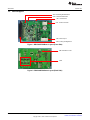
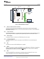
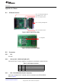
The DRV3204-Q1 pins are brought out to the test pin or test through-hole. For each test pin, a label on
the silkscreen identifies the signal. Access the signals by using 14 through-holes, marked as J1.
2
Connectors and Switches
This section describes the pin assignment of the connectors and switches.
2.1
2.1.1
Connectors
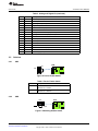
CN1 – B3P-VH-FB-B(LF)(SN) (JST)
Table 1. Power Connectors
Pin#
2.1.2
Name
Description
1
VB
External power supply (typ 12-V, max 10 A)
2
NC
No connection
3
GND
Base ground (B-GND)
CN2 – B5P-VH-FB-B(LF)(SN) (JST)
Table 2. Motor Outputs
2.1.3
Pin#
Name
Description
1
Motor1
Motor terminal 1
2
NC
3
Motor2
4
NC
5
Motor3
No Connection
Motor terminal 2
No Connection
Motor terminal 3
CN3 – FCN-365J032-AU (Fujitsu Component)
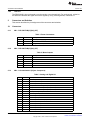
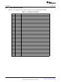
Table 3. Analog and Digital I/O
4
Pin#
Name
Description
A1
PMV1
Phase comparator output 1
B1
PMV2
Phase comparator output 2
A2
PMV3
Phase comparator output 3
B2
PSS1
Sample and hold control signal input 1 (not used)
A3
PSS2
Sample and hold control signal input 2 (not used)
B3
PSS3
Sample and hold control signal input 3 (not used)
A4
CS
B4
DOUT
SPI chip select signal input
SPI data signal output
A5
SCK
SPI clock signal input
B5
DIN
SPI data signal input
A6
CTLEN
Pre-driver parallel enable input (not used)
B6
CTLWL
Pre-driver parallel input
A7
CTLWH
Pre-driver parallel input
B7
CTLVL
Pre-driver parallel input
A8
CTLVH
Pre-driver parallel input
B8
CTLUL
Pre-driver parallel input
DRV3204-Q1 EVM
SLVU844 – February 2013
Submit Documentation Feedback
Copyright © 2013, Texas Instruments Incorporated