1
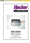
User Guide
Master Prog-Box
for programming
the new MASTER Controllers
MASTER Prog-Box programming sequence
SPRACHE
DEUTSCH
JETI & HACKER Vxx
WELCOME
LANGUAGE
ENGLISH
ENTER MODEL NAME
->------------------------------OK
MEMORY
MEMORY
X:
2:
MEMORY
1:
TYPE
TYPE
HELI
HELI
TYPE
AIRPLANE
CONTROLLER TYPE
CONTROLLER
TYPE
M-4-B-H
M-8-B-H
CONTROLLER TYPE
M-4-B-F
HELI MODE
CONSTANT
HELI
MODE RPM
CONSTANT RPM
BRAKE
OFF
MOTOR POLE NO.
2-4
TIMING
0°
TIMING
TIMING
0°
0°
Start
FREQUENCY
FREQUENCY
16 kHz LOW Ri
FREQUENCY
32kHz IRON FREE
ACCELERATION
SOFT
ACCELERATION
MEDIUM
ACCELERATION
HARD
ACCUMULATOR TYPE
NiCd/NiMh
ACCUMULATOR TYPE
Li-Ion/Li-Pol
8 kHz
NUMBER OF CELLS
2 LiIo/Po
NiCd/NiMh CUToff
V PER CELL min
NUMBER OF CELLS
NUMBER
3 LiIo/PoOF CELLS
3 LiIo/Po
LiIo/Po CUT OFF
LiIo/Po
CUT
OFF
V PER
CELL
2.0
V PER CELL 2.1
CUT OFF
SLOW DOWN
INITIAL POINT
FIXED 1.0 ms
INITIAL POINT
INITIAL
POINT
AUTOMATIC
FIXED 1.0 ms
END POINT
FIXED 1.7 ms
END POINT
END
POINT
AUTOMATIC
FIXED 1.7 ms
THROTTLE CURVE
LOGARITHMICAL
THROTTLE CURVE
LINEAR
ROTATION
RIGHT
ROTATION
RIGHT
TIMING MONITOR
ON
TIMING MONITOR
OFF
THROTTLE CURVE
EXPONENTIAL
MASTER Prog-Box
Menu Explanations
Menu Item
Parameter
Brake
Off
Explanation
Extra Soft
Soft
Brake activation and brake intensity
Medium
Hard
Extra Hard
Heli Mode
Normal / Constant RPM
Motor Pole No.
2-4, 6-10, 12-14
Reverse
On / Off
Current Limit
No Limit
20,30...100A
Timing
Frequency
NiCd/NiMh
20,40,60
RPM governor activation for Heli controllers
Adaptation of the controlling algorithm to the motor type or number of
poles (Heli controllers)
Selection: Forward/Brake — Forwards/Brake/Backwards (RC Car
controllers)
Activation and setting of current limits for RC Car controllers. Enables
maximum current limitation. No effect on brake settings!
Timing settings (advance) may be adjusted to suit the motor type.
2 Pole: 0...7°
4 Pole: 5...15°
8 Pole: 10...20°
0°, 1°,2°...30°
2°, 8°, 15° 30° 10 Pole and higher (outrunners like LRK): minimally 20°
Enables setting the frequency to suit the motor type.
8 kHz: universally recommended, lowest efficiency losses in the controller
16 kHz: recommended for low resistance/impedance motors
8, 16, 32 kHz
32 kHz: only recommended for motors with low inductivity
Acceleration
Soft / Medium / Hard
Accumulator Type
NiCd/NiMh - Li-Ion/Li-Pol
NiCd/NiMh Cut Off
min., 0.4, 0.5, ..., 1.0 V/Cell
Li-Ion/Li-Pol – Number of Cells
LiIo/Po AUTO
“Delayed”throttle response
Battery type selection
Enables setting the voltage per cell for the point at which the controller’
s
cut off circuitry engages.
Activates the automatic recognition of the number of cells for Li-Ion/LiPolymer batteries. Only for 2 and 3 cell battery packs.
2,3 LiIo/Po
2,3,4,5 LiIo/Po
Li-Ion/
Li-Pol
3,4,5, 6 LiIo/Po
Manual selection of the number of cells
4,5,6...10 LiIo/Po
3,4,5...10 LiIo/Po
Li-Ion/Li-Pol Cut Off
Cut Off
Initial Fixed Point
2.0, 2.1, 2.2 ....3.2 V/Cell
Slow Down / Hard
Automatic
Fixed 1,0...1,5 ms
End Point
Automatic
Fest 1,7...2,0 ms
Throttle Curve
Fixed setting for the throttle off point.
Automatic recognition of the full throttle motor setting. The transmitter’
s
throttle lever should be fully on. The trim should be set in the middle.
Fixed setting for the full throttle point.
Logarithmical
Linear
Enables setting the throttle curve independently of transmitter
programming.
Exponential
ABS
Enables setting the voltage per cell for the point at which the controller’
s
cut off circuitry engages. 3.0V/cell recommended!
Allows setting the low voltage cut off type.
The hard setting is highly recommended if the brake is disabled (typical
for non-sailplane models).
Automatic recognition of the motor off throttle setting. The transmitter’
s
throttle lever should be fully off. The trim should be set in the middle.
On / Off
ABS for brake functions (RC Car controllers)
Power Limit
Forwards: OFF, 75%, 50%, 25% RPM limiting for RC Car controllers
Power Limit
Backwards: OFF, 75%, 50%, 25% RPM limiting for RC Car controllers
Delay
0.25, 0.5, 0.75, 1, 1.5, 2, 5s
Forward Point
Automatic
Automatic recognition of the throttle lever position for forward motion
Fixed 1,0...1,3ms
Reverse/Brake Point
Automatic
Fixed 1,0...1,3ms
Rotation
Left / Right
Timing Monitor
On
Off
Delay between motor stop and reverse for Navy and RC Car controllers
Fixed setting for the forward point
Automatic recognition of the throttle lever position at which the
brake/reverse is activated
Fixed setting for the reverse/brake point
Motor rotation reversal via the controller’
s software
Activation of the timing monitor
A-4
M--48-O-Flight
M-77-O-Flight
M-90-O-ACRO
x
x
x
x
x
x
x
x
x
Soft
x
x
x
x
x
x
x
x
x
x
x
x
x
x
x
Medium
x
x
x
x
x
x
x
x
x
x
x
x
x
x
x
Hard
x
x
x
x
x
x
x
x
x
x
x
x
x
x
x
Extra Hard
x
x
x
x
x
x
x
x
x
x
x
x
x
x
x
Normal / Constant RPM
x
x
x
x
x
Motor Pole No.
2-4, 6-10, 12-14
x
x
x
x
x
Reverse
On / Off
Current Limit
No Limit
Menu Item
Heli Mode
Timing
x
x
x
x
x
x
x
x
x x
20,30...100A
20,40,60
0°, 1°,2°...30°
2°, 8°, 15° 30°
x x
x
x
x
x
x
x
x
x
x
x
x
x
x
x
x
x
x
x
x
x
x
x
x
x
x
x
x
x
x
x
x
x
x
x
x
x
x
x
x
x
x
x
x
x
x
x
x
x
x
x
x
x
x
x
x
x
x
x
x
x
x
x
x
x
x
x
x
x
Frequency
8, 16, 32 kHz
Acceleration
Soft / Medium / Hard
x
x
x
x
x
x
x
x
x
x
x
x
x
x
x
x
x
x
x
x
x
x
x
x
x
Accumulator Type
NiCd/NiMh - Li-Ion/Li-Pol
x
x
x
x
x
x
x
x
x
x
x
x
x
x
x
x
x
x
x
x
x
x
x
x
NiCd/NiMh Cut Off
min., 0.4, 0.5, ..., 1.0 V/Cell
x
x
x
x
x
x
x
x
x
x
x
x
x
x
x
x
x
x
x
x
x
x
x
x
Li-Ion/Li-Pol - Number of Cells
LiIo/Po AUTO
x
x
x
x
x
x
x
x
x
2,3 LiIo/Po
x
x
x
x
x
x
x
x
x
2,3,4,5 LiIo/Po
Li-Ion/ LiPol
x
x
x
x
3,4,5, 6 LiIo/Po
x
Cut Off
Initial Fixed Point
End Point
Throttle Curve
2.0, 2.1, 2.2 ....3.2 V/Cell
x
x
3,4,5...10 LiIo/Po
Li-Ion/Li-Po Cut Off
x
x
x
x
x
x
x
x
x
x
x
x
x
x
x
x
x
x
x
x
x
x
x
x
x
x
x
x
x
x
x
x
x
x
x
x
x
x
x
x
x
x
x
x
x
x
x
x
x
x
x
x
x
x
x
x
x
x
x
x
x
x
x
x
x
x
x
x
x
x
x
x
x
x
x
x
x
x
x
x
x
x
x
x
x
x
x
x
x
Automatic
x
x
x
x
x
x
x
x
x
x
x
x
x
x
x
x
x
x
x
x
Fixed 1,0...1,5 ms
x
x
x
x
x
x
x
x
x
x
x
x
x
x
x
x
x
x
x
x
Automatic
x
x
x
x
x
x
x
x
x
x
x
x
x
x
x
x
x
x
x
x
Fixed 1,7...2,0 ms
x
x
x
x
x
x
x
x
x
x
x
x
x
x
x
x
x
x
x
x
Logarithmical
x
x
x
x
x
x
x
x
x
x
x
x
x
x
x
x
x
x
x
Linear
x
x
x
x
x
x
x
x
x
x
x
x
x
x
x
x
x
x
x
Exponential
x
x
x
x
x
x
x
x
x
x
x
x
x
x
x
x
x
x
x
Hard
x
x
x
Slow Down
x
x
4,5,6...10 LiIo/Po
x
ABS
On / Off
x
x
x
x
x
x
x
x
Power Limit
Forwards: OFF, 75%, 50%, 25%
x
x
x
x
x
x
x
x
Power Limit
Reverse: OFF, 75%, 50%, 25%
x
x
x
x
x
x
x
x
Delay
0.25, 0.5, 0.75, 1, 1.5, 2, 5s
x
x
x
x
x
x
x
x
Forward Point
Automatic
x
x
x
x
x
Fixed 1.7, 1.8, 1.9, 2.0ms
x
x
x
x
x
Automatic
x
x
x
Fixed 1,0, 1.1, 1.2, 1.3ms
x
x
x
Left / Right
x
x
x
x
x
x
x
x
x
x
x
x
x
x
x
x
x
x
x
x
Timing Monitor
On
x
x
x
x
x
x
x
x
x
x
x
x
x
x
x
x
x
x
x
x
x
x
x
x
x
x
x
x
Off
x
x
x
x
x
x
x
x
x
x
x
x
x
x
x
x
x
x
x
x
x
x
x
x
x
x
x
x
M-8-B-Flight
M-18-B-Flight
M-30-B-Flight
M-40-B-Flight
M-40-O-Flight
M-70-B-Flight
M-70-O-Flight
M-125-O-F5F
M-135-O-F5B
M-195-O-F5B
M-90-O-F5D
M--48-O-Flight
M-77-O-Flight
M-90-O-ACRO
M-8-B-Heli
M-40-B-Heli
M-40-O-Heli
M-48-O-Heli
M-77-O-Heli
M-40-B-Navy
M-70-B-Navy
M-70-O-Navy
M-77-O-Navy
M-99-O-Navy
M-B-CAR-MINI
M-B-CAR-RACE
M-B-CAR-COMPET.
Menu Item
Rotation
M-4-B-Flight
Rev./Brake Point
Parameter
NiCd/NiMh
M-B-CAR-COMPET.
M-90-O-F5D
x
x
M-B-CAR-RACE
M-195-O-F5B
x
x
M-B-CAR-MINI
M-135-O-F5B
x
x
M-99-O-Navy
M-125-O-F5F
x
x
M-77-O-Navy
M-70-O-Flight
x
x
M-70-O-Navy
M-70-B-Flight
x
x
M-70-B-Navy
M-40-O-Flight
x
x
Brake
M-40-B-Navy
M-40-B-Flight
x
x
M-77-O-Heli
M-30-B-Flight
x
x
M-48-O-Heli
M-18-B-Flight
x
x
M-40-O-Heli
M-8-B-Flight
x
M-40-B-Heli
M-4-B-Flight
Off
Extra Soft
M-8-B-Heli
Parameter
MASTER-Prog-Box
Programming Options
The fields with a gray background indicate the default settings and are
programmable by use of a transmitter.
A-3
User Guide
Prog-Box
Thank you for purchasing a Hacker Brushless Motors product. The MASTER Prog-Box
was developed in close cooperation with JETI and incorporates the latest technological
developments. Hacker MASTER brushless, sensorless motor controllers are designed
with particular emphasis on reliability and easy, transmitter-based programming of most
parameters. The Prog-Box additionally leverages the greatly expanded programming
capabilities of these new controllers by allowing individual adjustment of virtually all parameters.
Although the programming sequences of the MASTER Controllers are particularly logical
and therefore quite simple, programming via the MASTER Prog-Box requires a little
knowledge and a few basic skills. Reading this user guide attentively prior to initial operation will enable you to familiarize yourself with the concepts of this device enabling quick
and sure programming. Please pay particularly close attention to the safety tips.
We wish you much joy and success with your MASTER series products.
Table of contents
Page
1.
2.
3.
4.
5.
6.
6.1
7.
8.
A-3
A-4
A-5
Safety and operating instructions
Limitation of liability
Product description
Connections and controls
Initial operation of the MASTER Prog-Box
Programming MASTER controllers using the Prog-Box
Operating principles
Warranty
Declaration of conformity
MASTER Prog-Box: Programming Options
MASTER Prog-Box: Menu Explanations
MASTER Prog-Box: Programming Sequences
2
3
4
4
5
5
6
6
6
7
MASTER Series
1.
Safety and operating instructions
Building and operating remotely controlled models requires a high level of technical competence, careful handling and a particular emphasis on safety. Inaccurate and faulty
construction as well as inattentive and careless operation can result in significant property and/or personal injuries. Consequently, particular emphasis should be placed on
working carefully and on the prudent operation of our controllers.
The CE mark guarantees the conformance with the applicable laws ensuring trouble free
operation; it does not however entitle you to careless handling of the controller. The
MASTER product series was developed exclusively for use in radio controlled models.
The controller may not be under any circumstances be used in man-carrying aircraft,
man-carrying vehicles or the like.
The MASTER Prog-Box is designed for use with batteries only. Do not use the Prog-Box
with a power supply, incorrect voltages can destroy it. Never connect the Prog-Box to
alternating current (typically 100-230 V).
Remove the propeller or other rotating objects prior to programming the controller. Be
sure to remove other objects that may be able to come into contact with the rotating parts
of the motor assembly. Mechanical or electrical defects may lead to sudden, unexpected
starting of the motor. Please be sure to protect yourself from the danger that may result
in particular from rotating propellers or rotor blades.
The Prog-Box should be protected against the effects of vibration, dust, moisture, shock
or pressure. Inspect the Prog-Box for damage at regular intervals. Should the device
have been exposed to moisture it should not be used again until it has been thoroughly
dried and closely inspected? The Prog-Box should not be used if it has been damaged
and must be sent to our service department for repair should you wish to use it in the
future.
No modifications or alternations of any type may be made to the Prog-Box.
Use the device only in ambient temperatures between –10oC/+14oF and +50oC/+122oF.
The Prog-Box may only be used in an environment free of static electricity.
The Prog-Box is not protected against reversed polarity, reversing the connecting leads
will cause it to be damaged or destroyed.
Should a BEC be used as the power source for the Prog-Box, a receiver battery may not
be connected in parallel. Doing so will inevitably result in the destruction of the BEC circuitry. If it is desirable to use a controller with BEC in conjunction with receiver battery,
then the red (+) connecting lead must be removed from the receiver connector of the
MASTER controller. When using the UNI connectors employed by the MASTER series, a
small screwdriver may be used to loosen the retaining mechanism and to then to push
the lead out of the connector. The loose end must be carefully insulated. Once the BEC
is inoperative a receiver battery may be connected without danger.
Connect the throttle servo cable of the controller to the corresponding connection on the
Prog-Box.
The MASTER Controllers are pre-set for optimal use with Hackler Brushless Motors on
delivery. The motor brake is activated for fixed wing models. Please refer to this user
guide for the appropriate settings for other motors.
3
User Guide
2.
Prog-Box
Limitation of liability
As Hacker Motor GmbH has no ability to ascertain whether our controllers are installed
and used in conformance with our recommendations, and as we can not verify how our
controllers were maintained, Hacker Motor GmbH can not assume any liability for losses,
damages or costs arising from their use. Any and all claims arising from the use, failure,
or malfunction of our products, or in any way arising in conjunction therewith, will be refused. Hacker Motor GmbH assumes no liability for personal injury, property damage or
consequential damages arising resulting from the use of our products or arising from our
workmanship. To the maximum legally permissible extent, liability claims arising for any
reason will be limited to the selling price of the Hacker Motors GmbH product involved.
Exceptions will only be made as required by legislation or if gross negligence on the part
of Hacker Motor GmbH results in the exclusion of the limitation of liability.
3.
Product description
MASTER controllers contain highly sophisticated circuitry and were specifically designed
for the use with Hacker brushless motors. Their flexible and effortless programmability
combined with support for different operating modes additionally makes them ideal for
use with other brushless motors. Compact dimensions enable these controllers to fit into
the smallest models.
All Master controllers may be programmed by using a transmitter or by using a MASTER
Prog-Box. While the programming capabilities available via transmitter are identical to
those provided by our previous MASTER controllers, the MASTER Prog-Box enables the
entire range of programming functionality to be accessed.
All settings must only be programmed once. The controller saves the configuration settings until they are overwritten by the next programming sequence. This holds true even
if the power source is disconnected.
An overview of all programming possibilities may be found in Annex A-3 and A-4.
4
MASTER Series
4.
Connections and controls
Please refer to the graphic below for overview of the connections and controls:
Battery
Display
Controller
Keypad
5.
Initial operation of the MASTER Prog-Box
The MASTER Prog-Box requires a power source for operation. A BEC controller or a
receiver battery may be connected for this purpose per the above diagram. Please be
sure to observe the proper polarity and ensure that the voltage is between 4.5V and
6.0V.
The motor is used as a loudspeaker to confirm MASTER Prog-Box programming sequences. It is essential that the motor be properly mounted according to its directions
and that the controller is correctly connected prior to beginning with programming.
Remove the propeller or other rotating objects prior to programming the controller. Be
sure to remove any and all objects that may be able to come into contact with the rotating parts of the motor assembly. As mechanical or electrical defects may lead to sudden,
unexpected starting of the motor please be sure to protect yourself from the danger that
may result. In particular that posed by rotating propellers or rotor blades.
Ensure that the controller cable is securely and correctly connected to the MASTER
Prog-Box. It is advisable to carefully check all connections to prevent malfunctions that
may lead to damage or destruction of the controller.
Finally, connect the motor’
s battery to the proper connectors on the controller. This connection is required for the motor to provide acoustical confirmation of the programming
sequences as described above.
5
User Guide
Prog-Box
6.
Programming MASTER controllers using the Prog-Box
6.1
Operating principles
Since the programming of the many different models of Hacker brushless controllers is
essentially identical, the individual programming steps described apply to all our controllers.
Please pay close attention to the programming sequences in Annex A-5
Ensure that the motor battery, or for controllers without BEC, the receiver battery, has
sufficient capacity for the programming to be completed. All changes to parameters or
settings are acoustically confirmed by the motor, the controller immediately saves the
new settings. Multiple parameters may be changed during each programming session
and the parameters may be changed as often as desired.
Please study the programming capabilities in Annex A-3 carefully
7.
Warranty
Every MASTER Prog-Box undergoes numerous tests during production and we place
particular emphasis on ensuring that our products are of the highest possible quality.
Hacker Motors GmbH products are covered by a 24-month warranty. The warranty is
limited to a free-of-charge repair provided proof of a material failure can be established.
We reserve the right to replace a device if an economically feasible repair is not possible.
Proof of warranty may be provided by the receipt or invoice issued in conjunction with the
purchase of the product. In the event of a repair, the warranty will not be extended. Incorrect use or operation arising for example from incorrect polarity, excessive voltage or
moisture will result in the denial of a warranty claim. Defects arising from wear and tear
or vibration will also be treated in the same manner. Any other claims, consequential
damages for example, are explicitly precluded. Also excluded are any and all liabilities
for damages arising from the device itself or use thereof.
All products returned for repair must be sent free-of-charge to Hacker Motor GmbH, parcels sent with postage or other fees due cannot be accepted. We can not assume responsibility or liability for damages or losses occurring in shipping.
Warranty claims will be honored provided that the following conditions are met:
•
•
•
•
The invoice or receipt for the product to be repaired is included
The product was used in accordance with this user guide
The product was used with the recommended voltages and currents
A clear description of the problem or defect is included
6
MASTER Series
8.
Declaration of conformity
The described products are in compliance with the relevant and applicable EC guidelines
for electromagnetic compatibility:
89/336/EWG
92/31/EWG
93/68/EWG
7