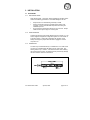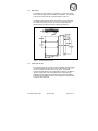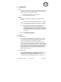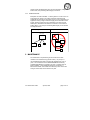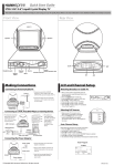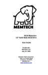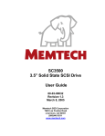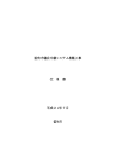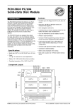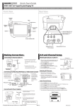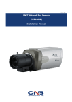
1
AT3525 3.5” Booster Rocket
3.5” IDE Solid State Flash Drive
User Guide
154180-001
Revision 1.0
April 23, 2004
Memtech SSD Corporation
7628 Las Positas Road
Livermore, CA 94550
(925)294-8483
(800)445-5511
www.memtech.com
Table of Contents
1.
HIGHLIGHTS
3
2.
INTRODUCTION
3
3.
INSTALLATION
4
3.1
PROCEDURE
3.1.1
ESD precautions
3.1.2
Configuration
3.1.3
Connector
3.1.4
Mounting
3.1.5
Computer setup
3.1.6
Partition
3.1.7
Format
3.2
JUMPERS
3.2.1
MASTER
3.2.2
SLAVE
3.2.3
CABLE SELECT
3.2.4
WRITE PROTECT
3.2.5
FACTORY DEFAULT
3.3
IDE INTERFACE
3.3.1
IDE Connector Pinout
4
4
4
4
5
5
6
6
6
7
7
7
7
8
8
8
4.
OPERATION
9
4.1
4.2
4.3
ECC
MTBF
POWER
4.3.1
Power Down
4.3.2
Power supply
4.3.3
Power routing
9
9
9
9
9
10
5.
MAINTENANCE
10
6.
SPECIFICATIONS
11
6.1
6.2
6.3
6.4
6.5
INTERFACE
PERFORMANCE*
ENVIRONMENTAL
POWER REQUIREMENTS
MECHANICAL
11
11
11
11
11
7.
APPENDIX
12
7.1
7.2
7.3
CONTACT INFORMATION
ATA SPECIFICATION INFORMATION
LIMITED LIFETIME W ARRANTY
3.5” Rocket User Guide
April 22, 2004
12
12
12
page 2 of 12
1. HIGHLIGHTS
•
•
•
•
•
•
•
•
•
•
•
•
64Mbyte to 4Gbyte uncompressed capacity
Full -40oC to +85oC operating temperature range
5 volt, low power operation
Completely solid state - no moving parts and no batteries
Extremely Rugged - 1000G operating shock, 15G operating vibration
3.5” drive form factor with a 40-pin, 0.1in standard IDE interface
72-bit Reed-Solomon ECC for exceptional data reliability
Power hold-up circuit
0.3 millisecond access time
5.4 Mbyte/secon sustained Read throughput
5.1 Mbyte/second sustained Write throughput
Pending CE and CSA Safety Compliance
2. INTRODUCTION
The AT3525 is the fastest member of the Rocket Family drives available
today. With a maximum capacity of 4 Gbyte in a standard 3.5” drive
form factor, it delivers exceptional value for its features. It is completely
solid state, with no moving parts. This accounts for the unit’s
exceptional ruggedness and wide operating temperature range.
The AT3525 employs sector erasable NAND EEPROMs (Flash) to
deliver up to 4 Gbytes of uncompressed, non-volatile solid state storage
in an extremely small, rugged form factor. Sustained host data
throughput is a 5.4 Mbytes per seconds for reads and 5.1
Mbytes/second for writes. The drive is 100% IDE compatible and
requires no special drivers to operate. It is essentially a drop in
replacement for standard rotating media.
The IDE interface is implemented using an application specific IDE
Flash controller with an integrated 72-bit Reed-Solomon error detection
and on-the-fly correction mechanism that enhance data reliability. The
ECC circuitry, in conjunction with the controller’s remapping algorithms,
makes for a virtually bulletproof medium for data retention.
The drive is available in a number of standard capacities ranging from
64 Mbytes to 4 Gbytes. Please contact the factory with your capacity
requirements. Disk compression utilities may be used to effectively
double the usable capacity of the drive.
Each drive is fully tested under environmental and voltage extremes, to
guarantee data integrity in even the harshest conditions.
3.5” Rocket User Guide
April 22, 2004
page 3 of 12
3. INSTALLATION
3.1 PROCEDURE
3.1.1 ESD PRECAUTIONS
Static electricity kills... electronics! Before handling the AT3525, please
observe the following precautions to avoid ESD damage to the unit:
•
•
•
Keep the drive in its shielded bag until ready to install.
Ground yourself by touching a grounded chassis frame of the
computer, or use a grounded wrist strap before and during the
installation process.
Do not touch the exposed drive electronics or connectors. Always
handle the drive by the edges or mounting rails.
3.1.2 CONFIGURATION
Configure the drive using the jumper diagrams given in Section 3.2. The
drive is shipped configured for a single drive system or as the master in
a two-drive system. Change the configuration as required. Never
attempt to change the jumpers while the drive is plugged in and the
computer is on.
3.1.3 CONNECTOR
The drive may be interfaced directly to a standard 3.5” 0.1in IDE socket
connector or a standard 40pin IDE ribbon and AT power cable. See
drawing below for pin 1 location. Care should be taken when installing
the AT3525 into the system, as misalignment can permanently damage
the drive interface connector or electronics.
Figure 1 - Drive Connector
3.5” Rocket User Guide
April 22, 2004
page 4 of 12
3.1.4 MOUNTING
The AT3525 may be mounted in any orientation. A total of four bottom
and six side mounting holes are available for installation. The mounting
holes require 6-40 screws with a maximum depth of 0.25 inch.
The diagram given below is valid for all capacities of the AT3525 drive.
The overall outside dimensions are 4 inch (101.6 mm) wide, 5.56 inch
(141.22mm) long, and 0.473 inch (12 mm) tall. Please refer to the
following drawing for dimensions and mounting hole locations.
Figure 2 - Mechanical Dimensions
3.1.5 COMPUTER SETUP
To be recognized by the computer, the drive translation information must
typically be entered into the System Setup or CMOS Setup utility. For
non-PC compatible computers, this may not apply. The AT3525
supports automatic detection and configuration if offered by the BIOS. If
the drive configuration must be manually entered, select drive type
USER and use the table below to determine proper setup parameters.
Automatic CHS translation and LBA mode is supported. Note that a MB
is equal to 1024*1024 bytes.
3.5” Rocket User Guide
April 22, 2004
page 5 of 12
Drive Type
AT3525-64
AT3525-128
AT3525-256
AT3525-512
AT3525-768
AT3525-1024
AT3525-1536
AT3525-2048
AT3525-2560
AT3525-3072
AT3525-3584
AT3525-4096
Physical
Capacity Cylinders
64 MB
977
128 MB
977
256 MB
980
512 MB
993
768 MB
1489
1024 MB
1986
1536 MB
2977
2048 MB
3969
2560 MB
4961
3072 MB
5953
3584 MB
6945
4096 MB
7937
Heads
4
8
16
16
16
16
16
16
16
16
16
16
Sectors
32
32
32
63
63
63
63
63
63
63
63
63
Available
Capacity
61 MB
122 MB
245 MB
489 MB
732 MB
977 MB
1465 MB
1953 MB
2442 MB
2930 MB
3418 MB
3906 MB
3.1.6 PARTITION
The drive must be partitioned using the system’s FDISK utility. For
operating systems other than DOS, please refer to your OS operating
guides. Note that changing the partition information will erase all data
currently on the drive. Refer to your OS manual for information
regarding partitioning a hard disk.
3.1.7 FORMAT
The AT3525 is low-level formatted at the factory, which establishes the
512-byte sector size. A high-level format is required after the partition
has been established on the drive. Refer to your OS manual for
information regarding hard disk drive format procedures.
3.2 JUMPERS
The following diagram illustrates the location of the drive selection
jumper on the AT3525. The jumper configuration controls the drive
selection and write protection. The jumper required is a 2-pin vertical
header on 0.1in centers.
Figure 3 - Configuration Jumpers
3.5” Rocket User Guide
April 22, 2004
page 6 of 12
3.2.1 MASTER
The master jumper allows the drive to be configured as a master.
3.2.2 SLAVE
The slave jumper allows the drive to be configured as a slave.
3.2.3 CABLE SELECT
The Cable Select jumper allows the drive to be configured as a master
or slave through the IDE cable. A maximum of two drives may only be
connected to one standard IDE cable. Connecting the drive to the end of
the cable configures the drive to be a master (DOS drive C:) and
connecting the drive to the middle connector of the cable configures the
drive for a slave (DOS drive D:).
3.2.4 WRITE PROTECT
The Write Protect jumper prevents data from being written to the drive.
3.5” Rocket User Guide
April 22, 2004
page 7 of 12
3.2.5 FACTORY DEFAULT
The factory default configuration is master. No jumpers are installed.
3.3 IDE INTERFACE
The AT3525 uses a unitized signal and power connector. Maximum
cable length is 18 inches. Recommended cable length is 12 inches or
less, especially if advanced PIO transfer modes are used.
3.3.1 IDE CONNECTOR PINOUT
The signal to pin assignment for the 40-pin IDE interface connector is
listed in the following table.
PIN
1
3
5
7
9
11
13
15
17
19
21
23
25
27
29
31
33
35
37
39
SIGNAL
RESETDATA7
DATA6
DATA5
DATA4
DATA3
DATA2
DATA1
DATA0
GND
NU
IOWIORIOCHRDY
NU
IRQ
ADDR1
ADDR0
CS0DASP-
3.5” Rocket User Guide
PIN
2
4
6
8
10
12
14
16
18
20
22
24
26
28
30
32
34
36
38
40
April 22, 2004
SIGNAL
GND
DATA8
DATA9
DATA10
DATA11
DATA12
DATA13
DATA14
DATA15
KEY (NO PIN)
GND
GND
GND
CSEL
GND
IOCS16PDIAGADDR2
CS1GND
page 8 of 12
4. OPERATION
4.1 ECC
The IDE controller utilizes a 72-bit Reed-Solomon Error Detection Code
(EDC) and Error Correction Code (ECC), which provides the following
error immunity for each 512-byte block of data:
1.
2.
Corrects up to three random 12-bit symbol errors.
Corrects single bursts up to 25 bits.
4.2 MTBF
The MTBF can be logically calculated in hours using the following
formula.
# Flash Chips * # Blocks *Re-programming Cycles * Area Rate
MTBF = -----------------------------------------------------------------------------------Average Programming Sectors per hour (1 sector = 512 bytes)
Note: The program area is the area that is not changed once it has
been programmed. The remainder of the drive is thus
considered “Reprogrammable”. In the case where 32 Kbytes (64
sectors) are written every 5 minutes into an area occupying 30%
of a 512 MB disk (1 Gbit x 4 chips), the MTBF is calculated as
shown below:
MTBF = (4*8192*250,000*0.3)/(64*12)
= 3.2 million hours (350 years)
4.3 POWER
4.3.1 POWER DOWN
The AT3525 is shipped with Memtech’s proprietary Kicker™ hold-up
circuit. The Kicker™ provides enough residual power for the drive to
complete a write sequence, thus avoiding data corruption.
Still, it is recommended that power not be removed from any mass
storage device while a write sequence is in progress. This is especially
true when disk-caching programs are being used. Though the Kicker™
protects against data corruption and media errors, it cannot prevent OS
or file errors from occurring. These types of errors arise when the OS
breaks a large transfer into many smaller ones, and only part of the
transfer arrives from the host.
4.3.2 POWER SUPPLY
The AT3525 voltage requirement is specified at +5 volts, +/- 5%.
Operation outside of these limits is not guaranteed. Note that the drive
will “operate” below this voltage, but reliability issues such as
uncorrectable errors or invalid data reads may occur. An on board
3.5” Rocket User Guide
April 22, 2004
page 9 of 12
voltage monitor will inhibit writes when the on-board supply voltage falls
below 3 volts, thus preserving data integrity on the drive.
4.3.3 POWER ROUTING
Bad power can lead to bad data. To avoid “glitches” or noise on the Vcc
and ground lines, power in the system should be routed so that all
peripherals are sourced from the power supply in a star configuration, as
opposed to routing a single continuous supply line to each device in the
system. Routing power in the star configuration, as is done on most
desktop PCs, will minimize the effect on one device’s current draw on
another device. This is key to maintaining data integrity on the AT1820.
See diagrams below.
Star Topology
Daisy Chain - Do Not Use
Power Supply
Power Supply
Main Board
Hard Disk
Floppy
Main Board
Hard Disk
Floppy
5. MAINTENANCE
No maintenance is required during the normal use of this drive.
If data is to be archived for long periods of time (> 10 years), it is
recommended that the data on the drive be refreshed every 5 to 10
years. The manufacturer of the NAND E2PROM devices will only
guarantee data integrity for a period of 10 years. Programs such as
Norton Speedisk©, which reallocates all sectors on the drive, or
Microsoft® Scandisk, which writes and reads every sector on the disk
during its surface test, achieve this end very well.
3.5” Rocket User Guide
April 22, 2004
page 10 of 12
6. SPECIFICATIONS
6.1 INTERFACE
IDE Compatibility
IDE Drive Number
Physical Capacity
Physical Sector Size
ATA-3 compliant
Drive 0 or 1
64 Mbytes to 4 Gbytes
512 bytes
6.2 PERFORMANCE*
Average Access
Track/Track Access
Sequential Read
Sequential Write
Random Read
Random Write
Weighted Average
0.3 ms
0.3 ms
5.4 Mbytes/sec sustained
5.1 Mbytes/sec sustained
4.0 Mbytes/sec sustained
5.6 Mbytes/sec sustained
5.0 Mbytes/sec
* 64 Kbyte transfers
6.3 ENVIRONMENTAL
Commercial Temperature Range
Operating
0o to 70o C
Storage
-45oC to 125o C
Extended Temperature Range
Operating
-20oC to 75oC
Storage
-45oC to 125o C
Industrial Temperature Range
Operating
-40o to 85o C
Storage
-55o to 125o C
Shock - operating
1000G Operating (target)
Vibration - operating
15G Random (target)
Airflow
None required
Humidity
5% to 95% NC (target)
6.4 POWER REQUIREMENTS
Voltage
Current
Idle
Read
Write
5V +/- 5%
AT3525-3072
45 mA
90 mA
112 mA
6.5 MECHANICAL
Length
Width
Height
Cable Interface
Max. Cable Length
Rec. Cable Length
Weight (3072 Mbytes)
3.5” Rocket User Guide
5.56 inches (141.22 mm)
4.00 inches (101.60 mm)
0.47 inches (12.01 mm)
40-pin, 0.1in
18 inches (457 mm)
12 inches (305 mm)
7.3 oz (208 g)
April 22, 2004
page 11 of 12
7. APPENDIX
7.1 CONTACT INFORMATION
For Technical Support or Warranty Repair information, please contact
Memtech at:
Memtech SSD Corporation
7628 Las Positas Road
Livermore, CA U.S.A. 94550
phone: (925) 294-8483 or (800) 445-5511
fax: (925) 294-5920
7.2 ATA SPECIFICATION INFORMATION
Information regarding the ATA-3 specification may be obtained from the
following locations:
AT-Attachment Document Distribution
Global Engineering
15 Inverness Way East
Englewood, Co. 80112-5704
Phone: (303) 792-2181 or (800) 854-7179
Fax: (303) 792-2192
ATA Anonymous FTP Site
fission.dt.wdc.com
ATA3 directory is: “/pub/standards/ata/ata-3”
7.3 LIMITED LIFETIME WARRANTY
Memtech warrants your AT3525 against defects in material and
workmanship for the life of the drive. The warranty is void in the case of
misuse, accident, alteration, improper installation, misapplication or the
result of unauthorized service or repair.
The implied warranties of merchantability and fitness for a particular
purpose, and all other warranties, expressed or implied, except as set
forth in this warranty, shall not apply to the products delivered.
In no event shall Memtech be liable for any lost profits, lost savings or
other incidental or consequential damages arising out of the use of, or
inability to use, this product.
BEFORE RETURNING PRODUCT, A RETURN MATERIAL
AUTHORIZATION (RMA) MUST BE OBTAINED FROM MEMTECH.
Product shall be returned to Memtech with shipping prepaid. If the
product fails to conform and warranty repair is necessary, Memtech will
reimburse customer for the transportation charges incurred.
3.5” Rocket User Guide
April 22, 2004
page 12 of 12