1
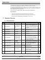
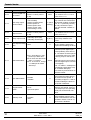
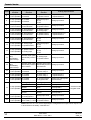
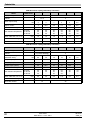
Parameter Overview
Parameter
Description
Range
Default
Explanations
0%
Allows the input voltage at which
speed starts to ramp up to be offset from zero. Is a percentage of
the full scale input voltage.
P2-32
Bipolar analog input
0–50.0%
offset
P2-33
0/24 V (digital input)
2 analog input for0–10 V
mat
4–20 mA, 0–20 mA
0/24 V
Determines the format of the 2nd
analog input. Selecting 0/24 V
sets up the input as a digital input.
P2-34
2nd analog input
scaling
100%
Scales the 2nd analog input by
the factor set in this parameter.
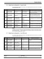
0–10 V
Determines the analog output
format. Min load impedance in
voltage mode 1 kOhm. Max load
impedance in current mode 1
kOhm.
101
Defines the extended menu access code used in P1-14.
nd
0–500%
P2-36
Analog output format
P2-37
Extended menu ac0…9999
cess code define
P2-38
Parameter Lock
0: Unlocked
1: Locked
P2-39
Hours run clock
0 to 99999 hours
Indicates the number of hours
Read only the drive has been running since
new.
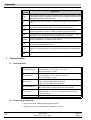
P2-40
Drive type/rating
“1 0.37”: 110 V 0.37 kW
“2 0.75”: 230 V 0.75 kW
“4 18.5”: 400 V 18.5 kW
Indicates the drive voltage and
Read only power rating. Fixed by the drive
hardware.
5.3
0–10 V, 4–20 mA
0
Set to
When locked, all parameter
changes are prevented.
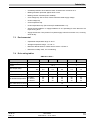
User feedback control (PID control)
P3-01
User PID controller Pro0.1–10
prtional Gain
P3-02
User PID controller Integral Gain
P3-03
User PID controller Dif0.01–0.1 s
ferential Gain
0
Set to zero (disabled) for most applications.
P3-04
User PID controller op- 0: Direct
erating mode
1: Inverse
0
If an increasing feedback signal should increase the
speed of the motor, set to 'inverse' mode.
P3-05
User PID controller ref- 0: Digital
erence select
1: Analog
0
Sets the source for the regulator reference signal.
When set to 1, the bipolar analog input is used.
P3-06
User PID digital reference
0
Sets the preset reference used when P3-05 = 0.
P3-07
User PID controller out- P3-08 to 100% of
put high limit
control range
P3-08
User PID controller out0 to P3-07
put low limit
12
0.1–10 s
0–100%
2
Higher value used for high inertia. Too high a value
gives instability.
1s
Higher value gives slower, more damped response.
100%
Preset PID controller output upper (speed) limit. P1-01
= 100%.
0
Preset PID controller output lower (speed) limit. P1-01
= 100%.
User Guide
09.06.04
SWP-Drive — 0.37–160.0
SWP_G