1
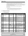
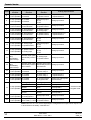
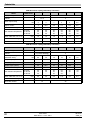
Parameter Overview
Parameter
Description
Range
P2-21
Display scaling fac0.000 to 30.000
tor
P2-22
Display scaling
source
P2-23
0: Disable
1: Enable + lo power
Brake circuit enable
2: Enable + hi power
3: Enable, no protection
P2-24
Effective switching
frequency
P2-25
Second deceleration ramp time
0: 2nd analog input
1: Speed
S1, 2S 230 V:
S2, S2 400 V:
S3 400V:
S4–S6 400 V:
4–32 kHz
4–32 kHz
4–32 kHz
4–16 kHz
0–3000 s
Default
Explanations
0.000
Disabled if zero. The variable selected in P2-22 is multiplied by
this factor and displayed as a real-time value on the drive, in addition to speed, current and power.
0
Selects the variable to be scaled
by the factor set in P2-21.
0
Activates the internal brake
chopper. Internal software overload protection when set to 1 and
2. See rating tables for resistor
sizing guidelines.
16 kHz
8 kHz
4 kHz
4 kHz
Effective power stage switching
frequency. Improved acoustic
noise and output current waveform occurs with increasing
switching frequency at the expense of increased losses within
the drive.
30 s
Selected automatically on mains
loss if P-05 = 0 or 2. Can also be
selected via digital inputs during
operation (see section 5.5).
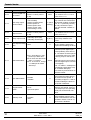
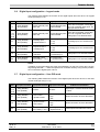
P2-26
S-ramp accel/decel 0: Disabled
time
1–50 Hz s-2
0
Determines the rate of increase
of acceleration/deceleration.
Used to give smoother speed
transitions. When 2nd decel
ramp (P2-25) selected, automatically adjusts S-ramps to proportionally match the 1st decel: 2nd
decel ramp time ratio.
P2-27
Drive communication address
1
Distinct drive address used for
all drive serial communications.
0
When in Master mode, drive
transmits its operational status
via the communication link. Used
to control other (slave) drives via
the serial communication link.
100%
The speed reference input to the
drive is scaled by this factor. Operates on both analog and digital
references. Can be used as an
electronic gearbox for Master/
Slave applications.
0–24 V
Configures the analog input format to match that of the ref signal.
100%
Scales the analog input by this
factor. Set to 200% to give full
speed range control with 0–5 V
in.
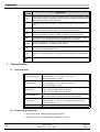
P2-28
0: Disable
1–63
Master/Slave mode 0: Slave mode
select
1: Master mode
P2-29
Speed scaling factor 0…500%, steps of 0.1%
P2-30
Bipolar analog input
0–24 V, 0–10 V, –10...10 V
format
P2-31
Bipolar analog input
0–500%
scaling
09.06.04
User Guide
SWP_G
SWP-Drive — 0.37–160.0
Set to
11