1
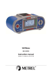
PRODUCT DESCRIPTION USER'S GUIDE The PTB110 barometer is a micro controller based barometer including a voltage or frequency output. The barometer can be supplied with several pressure ranges. The output of the barometer is a calibrated barometric pressure reading. The barometer uses the Vaisala BAROCAP® Sensor, a silicon capacitive sensor developed by Vaisala for barometric pressure measurement applications. The BAROCAP® sensor is especially designed for accurate and stable measurement of barometric pressure. INSTALLATION Vaisala BAROCAP® Barometer PTB110 Series The PTB110 barometer is intended to be installed indoors. Installing outdoors requires a protecting enclosure. A DIN rail mounting option enables the mounting of the barometer on a 35 mm wide standard DIN mounting rail. The barometer should be installed in a vertical position with the connectors pointing downwards to prevent accumulation of condensated water. Normal Mode The device is in the normal mode when the power on jumper is connected (see figure on the following page). In the normal mode the barometer continuously when powered-up. measures Shutdown Mode The device is in the shutdown mode when the power on jumper is not connected. In the shutdown mode, the barometer can be turned on or off by switching the pin 1. The pin 1 is located at the customer port, on the left edge of the screw terminal. NOTE The other jumpers inside the barometer are set at the factory and they must not be touched. ELECTRICAL CONNECTIONS The PTB110 barometer contains a screw terminal block located at the customer port. The screw terminal includes the electrical input/output pins presented in the table below. Pins in screw terminal Description/Value Pin 1: EXT_TRIG External trigger input Pin 1 is used as a power on/off switch in shutdown mode as follows: Power off 0 VDC Power on 5 VDC Pin 2: AGND Pin 3: GND Pin 4: SUPPLY Pin 5: VOUT/FOUT Analog ground Ground Supply voltage Voltage output/ Frequency output – Several pressure ranges – Accuracy ±0.3 hPa at +20 °C – Long-term stability ±0.1 hPa/year – On/off control with external trigger – Output voltage 0 … 2.5 or 0 … 5 VDC, In the normal mode no connection to the Pin 1 EXT_TRIG is recommended. frequency output – Current consumption less than 4 mA – Mountable on a (35 mm wide) DIN rail – NIST traceable (certificate included) – BAROCAP® sensor www.vaisala.com M210839EN-A The barometer is protected against a reverse operating voltage. OPERATING MODES The PTB110 barometer has two operating modes, the normal and the shutdown mode. The factory setting is the normal mode. 1 Both grounds (AGND and GND) are in the same electrical potential in the barometer. Both three-wire and four-wire connections can be used. However, it is recommended to use the four-wire connection, especially if the signal wires are long. The connections can be made as illustrated below. INSERTING AND REMOVING THE COVER ADJUSTMENT AND CALIBRATION The adjust buttons and the power on jumper are located inside the barometer. In order to adjust the measurement, the plastic cover of the barometer must be removed. Calibration of the PTB110 series barometers is NIST traceable and the barometers are supplied with a NIST traceable calibration certificate. For safety reasons, turn off the power when opening the cover. You can power off the device by pulling out the connector from the customer port. Correspondingly, you can power on the device by plugging the connector back into the customer port. There are two push buttons available for the offset fine adjustment inside the barometer (see the figure on the previous page). The adjustment step is 0.05 hPa. OPERATING THE BUTTONS Removing the Cover Restoring Adjustments Stick a flat-end screwdriver between the cover and the metal mounting plate. As you press the tool slightly, the cover will open up. To restore the adjustments, press and hold down the left button while switching on the barometer. After releasing the button, a green LED starts flashing. Inserting the Cover When the factory adjustments are in use, the green LED flashes twice. When the user adjustments are in use, the green LED flashes three times. READING THE OUTPUT Place the short and solid side of the cover against the left edge of the metal plate. Ensure that the metal clamps slide into the hollows in the cover. Then press the cover against the metal plate until it clicks in place. The barometric pressure (P) can be calculated from the measured output voltage (Uout) using a simple equation. INNER STRUCTURE OF THE BAROMETER P = Plow + where: Plow Prange Urange Uout Prange U range ⋅ U out P = 500hPa + NOTE Using Analog Output Test Mode The function forces the voltage or frequency output to 50% of the scale. As an indication of the test mode, the red LED is lit. Return to the normal operating mode by switching the power off and on in sequence. Offset Correction To activate the offset correction mode, press and hold down both buttons switching on the barometer. 500...1100 hPa 0...5 V 4V (1100 − 500)hPa ⋅ 4V 5V The green and red LEDs are lit. Now you can adjust the offset correction upwards or downwards. Each time when pressing the left button, the offset goes down by one step (5 Pa), and the green LED flashes once. Each time when pressing the right button, the offset goes up by one step (5 Pa), and the red LED flashes once. Return to the normal operating mode by switching the power off and on in sequence. = 980hPa The low end of the output voltage range of the barometer saturates at about 50 mV. In the frequency output 1 hPa equals 1 Hz. www.vaisala.com Return to the normal operating mode by switching the power off and on in sequence. To activate the test mode, press and hold down the right button while switching on the barometer. = Lower limit of the pressure range [hPa] = Pressure full range [hPa] = Voltage full range [V] = Measured output voltage [V] Example Pressure range Voltage output Measured output voltage Now you can change the factory adjustments to user adjustments or vice versa by pressing the left button. M210839EN-A 2 Dimensions TECHNICAL DATA General Operating range (1 hPa=1 mbar) Description/Value Pressure ranges Temperature range Humidity range 500...1100 hPa 600...1100 hPa 800...1100 hPa 600...1060 hPa 800...1060 hPa -40...+60°C Non-condensing Accuracy Linearity* Hysteresis* Repeatability* Calibration uncertainty** Accuracy at +20 °C*** Description/Value ±0.25 hPa ±0.03 hPa ±0.03 hPa ±0.15 hPa ±0.3 hPa Notes Description / Value * Defined as ±2 standard deviation limits of end-point non-linearity, hysteresis error or repeatability error ** Defined as ±2 standard deviation limits of inaccuracy of the working standard including traceability to NIST Defined as the root sum of the squares (RSS) of endpoint non-linearity, hysteresis error, repeatability error and calibration uncertainty at room temperature *** Total accuracy www.vaisala.com M210839EN-A +15...+25 °C ±0.3 hPa 0...+40 °C -20...+45 °C -40...+60 °C Long-term stability ±0.6 hPa ±1.0 hPa ±1.5 hPa ±0.1 hPa/year 3 Supply voltage 10...30 VDC Supply voltage control Supply voltage sensitivity Current consumption With TTL level trigger Negligible Less than 4 mA Less than 1 µA in shutdown mode Output voltage 0...2.5 VDC 0...5 VDC Output frequency 500...1100 Hz Resolution 0.1 hPa Load resistance 10 kohm minimum Load capacitance 47 nF maximum Settling time 1 s to reach full accuracy after powerup Response time 500 ms to reach full accuracy after a pressure step Acceleration sensitivity Negligible Pressure connector M5 (10-32) internal thread Pressure fitting Barbed fitting for 1/8" Minimum pressure limit 0 hPa abs Maximum pressure limit 2000 hPa abs Electrical connector A removable connector for five wires (AWG 28...16) Terminals Pin 1: External triggering Pin 2: Signal ground Pin 3: Supply ground Pin 4: Supply voltage Pin 5: Supply output Housing material plastic ABS/PC blend cover Metal mounting plate AI Weight 90 g Housing classification IP 32 SAFETY PRECAUTIONS RECYCLING The PTB110 delivered to you has been tested for safety and approved as shipped from the factory. Note the following precautions: WARNING CAUTION Recycle all applicable material. Ground the product, and verify outdoor installation grounding periodically to minimize shock hazard. This warranty does not however apply when the defect has been caused through Dispose of batteries and the unit according to statutory regulations. Do not dispose of with regular household refuse. Do not modify the device. Improper modification can damage the product or lead to malfunction. WARRANTY ESD Protection Electronic Discharge (ESD) can cause immediate or latent damage to electronic circuits. Vaisala products are adequately protected against ESD for their intended use. However, it is possible to damage the product by delivering electrostatic discharges when touching, removing, or inserting any objects inside the equipment housing. To make sure you are not delivering high static voltages yourself: • • Handle ESD sensitive components on a properly grounded and protected ESD workbench. When this is not possible, ground yourself to the equipment chassis before touching the boards. Ground yourself with a wrist strap and a resistive connection cord. When neither of the above is possible, touch a conductive part of the equipment chassis with your other hand before touching the boards. Always hold the boards by the edges and avoid touching the component contacts. Vaisala hereby represents and warrants all Products manufactured by Vaisala and sold hereunder to be free from defects in workmanship or material during a period of twelve (12) months from the date of delivery save for products for which a special warranty is given. If any Product proves however to be defective in workmanship or material within the period herein provided Vaisala undertakes to the exclusion of any other remedy to repair or at its own option replace the defective Product or part thereof free of charge and otherwise on the same conditions as for the original Product or part without extension to original warranty time. Defective parts replaced in accordance with this clause shall be placed at the disposal of Vaisala. Vaisala also warrants the quality of all repair and service works performed by its employees to products sold by it. In case the repair or service works should appear inadequate or faulty and should this cause malfunction or nonfunction of the product to which the service was performed Vaisala shall at its free option either repair or have repaired or replace the product in question. The working hours used by employees of Vaisala for such repair or replacement shall be free of charge to the client. This service warranty shall be valid for a period of six (6) months from the date the service measures were completed. This warranty is however subject to following conditions: a) A substantiated written claim as to any alleged defects shall have been received by Vaisala within thirty (30) days after the defect or fault became known or occurred, and www.vaisala.com M210839EN-A b) The allegedly defective Product or part shall, should Vaisala so require, be sent to the works of Vaisala or to such other place as Vaisala may indicate in writing, freight and insurance prepaid and properly packed and labelled, unless Vaisala agrees to inspect and repair the Product or replace it on site. 4 a) normal wear and tear or accident; b) misuse or other unsuitable or unauthorized use of the Product or negligence or error in storing, maintaining or in handling the Product or any equipment thereof; c) wrong installation or assembly or failure to service the Product or otherwise follow Vaisala's service instructions including any repairs or installation or assembly or service made by unauthorized personnel not approved by Vaisala or replacements with parts not manufactured or supplied by Vaisala; d) modifications or changes of the Product as well as any adding to it without Vaisala's prior authorization; e) other factors depending on the Customer or a third party. Notwithstanding the aforesaid Vaisala's liability under this clause shall not apply to any defects arising out of materials, designs or instructions provided by the Customer. This warranty is expressly in lieu of and excludes all other conditions, warranties and liabilities, express or implied, whether under law, statute or otherwise, including without limitation any implied warranties of merchantability or fitness for a particular purpose and all other obligations and liabilities of Vaisala or its representatives with respect to any defect or deficiency applicable to or resulting directly or indirectly from the Products supplied hereunder, which obligations and liabilities are hereby expressly cancelled and waived. Vaisala's liability shall under no circumstances exceed the invoice price of any Product for which a warranty claim is made, nor shall Vaisala in any circumstances be liable for lost profits or other consequential loss whether direct or indirect or for special damages.