1
User Manuals
Sartorius climate sensors
for Sartorius climate station YCM16C
Temperature & Humidity sensor YCM16H
Temperature sensor YCM16T
Pressure sensor YCM16P
98648-019-12
98648-019-12
Safety Instructions
Safety Instructions
t Before operating with or at the device | product, read
through the operating instructions.
This manual contains instructions which should be followed on mounting, start-up, and operation.
A non-observance might cause:
– failure of important functions
– Endangering of persons by electrical or mechanic effect
– Damages at objects
t Mounting, electrical connection and wiring of the
device | product must be carried out only by a qualified
technician who is familiar with and observes the engineering regulations, provisions and standards applicable
in each case.
t Repairs and maintenance may only be carried out by
trained staff or Sartorius Weighing Technology GmbH.
Only components and spare parts supplied and | or
recommended by Sartorius Weighing Technology GmbH
should be used for repairs.
t Electrical devices | products must be mounted and wired
only in voltage-free state.
Documentation
t © Copyright Sartorius Weighing Technology GmbH,
Goettingen | Germany
t Although this operating instruction has been drawn up
with due care, Sartorius Weighing Technology GmbH can
accept no liability whatsoever for any technical and
typographical errors or omissions in this document that
might remain.
t We can accept no liability whatsoever for any losses
arising from the information contained in this document.
t Subject to modification in terms of content.
t The device | product should not be passed on without
the | these operating instructions.
2
User manuals climate sensors
t Sartorius Weighing Technology GmbH guarantees
proper functioning of the device | products provided that
no modifications have been made to the mechanics,
electronics or software, and that the following points are
observed:
t All information, warnings and instructions for use
included in these operating instructions must be taken
into account and observed as this is essential to ensure
trouble-free operation and a safe condition of the
measuring system | device | product.
t The device | product is designed for a specific application
as described in these operating instructions.
t The device | product should be operated with the accessories and consumables supplied and | or recommended
by Sartorius Weighing Technology GmbH.
t Recommendation: As it is possible that each measuring
system | device | product under certain conditions, and in
rare cases, may also output erroneous measuring values,
it is recommended to use redundant systems with plausibility checks with security-relevant applications.
Contents
Contents
1.1
1.2
1.3
1.4
1.5
1.6
User manual for temperature & humidity
sensor YCM16H . . . . . . . . . . . . . . . . . . . . . . . . . . . . 4
Model . . . . . . . . . . . . . . . . . . . . . . . . . . . . . . . . . . . . 4
Application . . . . . . . . . . . . . . . . . . . . . . . . . . . . . . . . 4
Mounting . . . . . . . . . . . . . . . . . . . . . . . . . . . . . . . . . 4
Maintenance . . . . . . . . . . . . . . . . . . . . . . . . . . . . . . . 4
Connection Diagram . . . . . . . . . . . . . . . . . . . . . . . . . 5
Technical Data . . . . . . . . . . . . . . . . . . . . . . . . . . . . . 6
2
2.1
2.2
2.3
2.4
2.5
2.6
User manual for temperature sensor YCM16T . . . . . 7
Model . . . . . . . . . . . . . . . . . . . . . . . . . . . . . . . . . . . . 7
Application . . . . . . . . . . . . . . . . . . . . . . . . . . . . . . . . 7
Mounting . . . . . . . . . . . . . . . . . . . . . . . . . . . . . . . . . 7
Maintenance . . . . . . . . . . . . . . . . . . . . . . . . . . . . . . . 7
Connection Diagram . . . . . . . . . . . . . . . . . . . . . . . . . 8
Technical Data . . . . . . . . . . . . . . . . . . . . . . . . . . . . . 9
1
3 User manual for pressure sensor YCM16P . . . . . . . 10
3.1 Model . . . . . . . . . . . . . . . . . . . . . . . . . . . . . . . . . . . 10
3.2 Application | Construction | Mode of operation . . . . . 10
3.3 Mechanical Mounting . . . . . . . . . . . . . . . . . . . . . . . 10
3.4 Electrical Mounting . . . . . . . . . . . . . . . . . . . . . . . . 11
3.4.1Connection Options . . . . . . . . . . . . . . . . . . . . . . . . 11
3.5 Evaluation . . . . . . . . . . . . . . . . . . . . . . . . . . . . . . . 11
3.6 Maintenance . . . . . . . . . . . . . . . . . . . . . . . . . . . . . . 11
3.7 Technical Data . . . . . . . . . . . . . . . . . . . . . . . . . . . . 12
3.8 Dimensional Drawing (inch | mm) . . . . . . . . . . . . . . 12
4
EC-Declaration of Conformity . . . . . . . . . . . . . . . . 13
User manuals climate sensors
3
1 User manual for temperature & humidity sensor YCM16H
1 User manual for temperature & humidity sensor YCM16H
1.1 Model
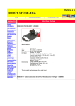
Order No.
Measuring
range
Humidity
output
Temperature
output
Operating
voltage
Sensorprotective filter
Constrution | Connection
YCM16H
0 … 100 % r. H.
–30 … +100 °C
0…1V
Pt 100
6 … 30 V DC
ZE20
Cable gland (Ms), 5 m cable
1.2 Application
1.3 Mounting
The temperature & humidity sensor is designed to measure
relative humidity, the air temperature and other non-aggressive gases.
For correct measurements, the temperature & humidity sensor should be mounted at a site in the room which is
representative of the climate within the room. The mounting
position itself is arbitrary. Mount the sensor such that water
cannot penetrate the inside of the sensor. Dewing and sprinkling water do not damage the sensor.
The use of capacitive humidity sensors is a guarantee for:
t a high degree of long-term stability
t nearly linear characteristics
t good dynamic behaviour
t dewing stability
t low temperature coefficients
t low hysteresis
The temperature & humidity sensor includes a Membrane-
filter ZE20 for field work. It protects the instrument against
dust and wind speeds up to 10 m | s.
Moreover, please make sure to keep the operating voltages as well as a good recirculation ventilation of the instrument.
Deviations might lead to measurement errors (for example:
due to instrument warming).
Preferably, the sensor should be mounted vertically facing
downwards to a wall (indoor application), and should be
mounted horizontally facing backwards in canals.
1.4 Maintenance
The temperature & humidity sensor is supplied already calibrated and its characteristics remain stable for years.
Dust does not damage the humidity sensor but does influence the dynamic behaviour negatively. If the instrument is
very dirty, the sensor element can be cleaned or carefully
rinsed in distilled water. Make sure you do not touch the
highly-sensitive sensor element.
Before cleaning the sensor elements please remove the protecting filter; it should be cleaned, as well or should be
replaced.
3
4
User manuals climate sensors
The instrument housing with the electronics
included should be opened only in the factory.
1 User manual for temperature & humidity sensor YCM16H
1.5 Connection Diagram
YCM16H
Temperature & Humidity sensor
Pg / Cable
Shield
1
2
H+
0...1 V
0 0...100%
rel.H.
5
6
+
–
Power Supply
6...30 V DC
7
8
9
10
T1
T1
T2
T2
Earth
Pt 100 Output
User manuals climate sensors
5
1 User manual for temperature & humidity sensor YCM16H
1.6 Technical Data
Humidity
Measuring element
Capacitive
Measuring range
0 … 100 % rel. humidity
Accuracy
± 2 % rel. humidity
Uncertainly, DKD (k=2)
± 0.51 % rel. humidity
Long-term stability per year
< 1 % rel. humidity
Repeatability
± 0,50 %
Temperature
Measuring element
Pt 100 class B, 1/3 DIN tolerance
Measuring range
-40 … +100 °C
Accuracy at output Pt100, 1/3 DIN
± 0.1 °C
Long-term stability per year
± 0.05 %
Additional Specifications
Ambient temperature
-40 … +100 °C
Degree of protection sensor
IP 30
Degree of protection electronics, connecting head
IP 65
Operating voltage
U-Output (0 … 1 V)
6 … 30 V DC
Load resistor
U-Output (0 … 1 V)
≥ 2 kΩ
Instrument current requirements
Humidity (0 … 1 V)
< 1 mA
Dimension to model YCM16H
Diameter
20 mm
Shaft length
122 mm
Total length
145 mm
Weight
0.45 kg
6
User manuals climate sensors
2 User manual for temperature sensor YCM16T
2 User manual for temperature sensor YCM16T
2.1 Model
Order No.
Measuring range
Electrical output
Connection
YCM16T
–30 … +70°C
Pt 100
Cable gland (Ms), 5 m cable
2.2 Application
2.4 Maintenance
The temperature sensor with connected cable is designed to
measure the air temperature and other non-aggressive gases.
The temperature sensor is supplied already calibrated and its
characteristics remain stable for years.
The temperature sensor includes a Membrane-filter ZE20 for
field work. It protects the instrument against dust and wind
speeds up to 10 m/s.
Dust does not damage the Pt100- temperature sensor but
does influence the dynamic behaviour negatively. If the
instrument is very dirty, the Pt100- temperature sensor can
be cleaned or carefully rinsed in distilled water. Make sure
you do not touch the highly-sensitive sensor element.
2.3 Mounting
For correct measurements, the temperature sensor should be mounted at a site of the room which is representative of
the climate within the room. The mounting position itself is
arbitrary. Mount the sensor such that water cannot penetrate
the inside of the sensor. Dew and jets of water do not harm
the sensor.
Before cleaning the Pt100-temperature sensor please remove
the protecting filter; it should be cleaned, as well.
3
The instrument housing with the electronics
included should be opened only in the factory.
Moreover, you should care for a minimum air flow and the operating voltage to be maintained. Deviations can lead
to errors (e.g. due to self-heating) in the measuring values.
Preferably, the sensor should be mounted vertically facing
downwards to a wall (indoor mounting) and should be
mounted horizontally facing backwards in canals. When
using the sensor in the open air Weather- and Thermal
Radiation Shield is recommended. It reduces to a minimum
the possibility of direct radiation or precipitation influencing
the data in a negative manner. In addition, it protects the
temperature sensor from damaging environmental influences. If the measuring place is badly ventilated, it is recommendable to use a Weather- and Thermal Radiation Shield
with force ventilation.
User manuals climate sensors
7
2 User manual for temperature sensor YCM16T
2.5 Connection Diagram
YCM16T
Temperature sensor
Pg / Cable
Shield
7
T1
8
T1
9
T2
Pt 100
Output
8
User manuals climate sensors
10
T2
Earth
2 User manual for temperature sensor YCM16T
2.6 Technical Data
Temperature
Measuring element
Pt 100 class B, 1/3 DIN tolerance
Measuring range
–30 … +70 °C
Accuracy at output Pt 100, 1/3 DIN
± 0.1 °C
Long-term stability per year
± 0.05 %
Additional Specifications
Ambient temperature
–40 … +80 °C
Protection Sensor | Electronic
IP 30 | IP 65
Operating voltage
passive
Connection
see model
Dimension to model YCM16T
Diameter
20 mm
Shaft length
122 mm
Total length
145 mm
Weight
0.35 kg
User manuals climate sensors
9
3 User manual for pressure sensor YCM16P
3 User manual for pressure sensor YCM16P
3.1 Model
Order No.
Measuring range
Output
Operating voltage
YCM16P
800 … 1060 hPa
0 … 5 V DC
9.5 … 28 V DC
3.2 Application | Construction | Mode of operation
3.3 Mechanical Mounting
The pressure sensor measures the „ABSOLUTE AIR PRESSURE“
of at the location. The pressure sensor is designed for use in
environmental applications that require excellent accuracy,
fast dynamic response, and long-term stability and reliability.
The pressure sensor is used with air (up to 95% r. h.), and
non-conducting gases.
To withstand the environmental extremes typically found in
Automatic Weather Stations, the transmitter housing is made
of environmental- and weather-proof materials. The electric
connection is carried out via a 5-pole connector with screw-clamp.
The instrument operates in the temperature range form –40° to + 60°C. The analogue output from 0 – 5 V DC can
be operated alternatively as 3- or 4-wire-circuit. The voltage
supply is within a range from 9,5 – 28 V DC. The current
consumption in the measurement mode is 3 mA nominal.
In the pressure sensor a capacitive ceramic-absolute-pressure
sensor is used which features excellent thermal and mechanic
stability.
10
User manuals climate sensors
3
The use with liquids or corrosive gases may
damage the instrument!
The pressure sensor is equipped with a 1/8” hose connection,
and is typically installed indoors or in weatherproof housing.
The pressure sensor should be installed vertically (connection
clamp downwards) to prevent any ingress of condensed
water.
3.4 Electrical Mounting
3 User manual for pressure sensor YCM16P
3.5 Evaluation
The barometric pressure (P) can be calculated from measured
output voltage (U) using an equation:
P = Plow +
Plow Prange Urange Uout Fig. 1
Four wire connection
Fig. 2
Three wire connection
Anschlussbelegung der Klemmleiste:
No.
Terminal strip
Function
1
EXT TRIG
no function
2
AGND*
analogue signal ground
3
GND*
supply ground (-)
4
SUPPLY
supply (+)
5
VOUT
output
Prange
Uout
Urange
Lower limit of the pressure range [hPa]
Pressure full range [hPa]
Voltage full range [V]
Measured output voltage [V]
Example for YCM16P:
Pressure range:
Voltage output:
Measured output voltage:
P = 800 hPa +
800 … 1060 hPA
0…5V
4V
(1060–800) hPa
4 V = 1008 hPa
5V
3.6 Maintenance
Maintenance is not required. The pressure sensor is factory
calibrated.
* Both grounds (AGND and GND) are in the same electrical
potential in the pressure sensor.
3.4.1 Connection Options
The ground connections AGND and GNG are in the same
electrical potential. The connection is carried out in four- or
three-wire-technology (see fig. 1 and 2). Four wire connection is recommended to avoid the voltage drop in the supply
ground line, which can affect the accuracy of the pressure
measurement. In normal operating mode no connection to
the EXT.TRIG terminal is recommended. The pressure sensor
is protected against reverse operating voltage.
User manuals climate sensors
11
3 User manual for pressure sensor YCM16P
3.7 Technical Data
Pressure
Measuring element
Capacitive
Measuring range
800 … 1060 hPa
Accuracy
± 0.3 hPa
Uncertainly, DKD (k=2)
± 0.27 hPa
Long-term stability per year
± 0.1 hPa
Repeatability
± 0.02 hPa
General
Electrical output
0 … 5 V DC (0 V saturation voltage = 20 mV)
Operating voltage
9.5 … 28 V DC
Current consumption
3 mA
Electrical connection
Three- or four-wire technology
Ambient temperature
-40 … +60 °C
Connection
5 pole terminal strip
Dimensions to model YCM16P
Dimensions
61 + 91 + 25 mm
Weight
0.14 kg
3.8 Dimensional Drawing (inch | mm)
12
User manuals climate sensors
4 EC-Declaration of Conformity
User manuals climate sensors
4 EC-Declaration of Conformity
13
4 EC-Declaration of Conformity
14
User manuals climate sensors
Sartorius Weighing Technology GmbH
Weender Landstrasse 94-108
37075 Goettingen, Germany
Phone +49.551.308.0
Fax +49.551.308.3289
www.sartorius.com
Copyright by Sartorius, Goettingen, Germany.
No part of this publication may be
reprinted or translated in any form or
by any means without prior written
permission from Sartorius. All rights reserved by Sartorius in
accordance with copyright law.
The information and figures contained
in these instructions correspond to the
version date specified below. Sartorius
reserves the right to make changes to
the technology, features, specifications
and design of the equipment without
notice.
Status: November 2011, Sartorius Weighing Technology GmbH, Goettingen, Germany
Printed in Germany Printed on paper bleached without chlorine.
W_Klimasensoren_YCM16C · KT
Publication no.: WCM6008-e11111