1
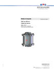
Operating instructions - Translation of the original - KI-DS Double sealing single seat valves Type: 5521, 5522, 5523, 5524 pneumatic and manual operation 10.9.15 English GBR KIESELMANN GmbH Paul-Kieselmann-Str.4-10 D - 75438 Knittlingen +49 (0) 7043 371-0Fax: +49 (0) 7043 371-125 www.kieselmann.de [email protected] 1 1. List of contents 1. List of contents ..............................................................................................................................2 2. General safety instructions ............................................................................................................3 2.1 Information for your safety .................................................................................................3 2.2 Marking of security instructions in the operating manual ...................................................3 2.3 Designated use ..................................................................................................................3 2.4 Personnel ...........................................................................................................................3 2.5 Modifications, spare parts, accessories .............................................................................3 2.6 General instructions ...........................................................................................................3 3. Safety instructions .........................................................................................................................4 3.1 Field of application .............................................................................................................4 3.2 General safety instructions ................................................................................................4 3.3 General notes ....................................................................................................................4 4. Installation informations.................................................................................................................4 4.1 Installation instructions.......................................................................................................4 4.2 Welding guidelines .............................................................................................................4 4.3 ATEX guidelines ................................................................................................................4 5. Function.........................................................................................................................................5 5.1 Functional description ........................................................................................................5 5.2 Basic position for pneum. operation valves........................................................................5 6. Service and maintenance..............................................................................................................6 6.1 Maintenance ......................................................................................................................6 6.2 Cleaning .............................................................................................................................6 7. Control system - and interrogation system ....................................................................................6 7.1 Control head -optional- ......................................................................................................6 7.2 Sensor mounting set -optional- ..........................................................................................6 8. Technical data ...............................................................................................................................7 9. Pneumatic valve actuation ............................................................................................................7 9.1 Actuator: air open - spring close (NC)...............................................................................7 10. Disassembly and assembly...........................................................................................................8 10.1 Disassembly.......................................................................................................................8 10.2 Assembly ...........................................................................................................................9 11. Drawing .......................................................................................................................................10 11.1 Pilot valves (EV) and (AV)................................................................................................11 12. Dimensions..................................................................................................................................12 12.1 Size measurement table ..................................................................................................12 12.2 Dimensioned drawing ......................................................................................................12 13. Wearing parts .............................................................................................................................13 13.1 Valve insert (VE) ..............................................................................................................13 13.2 Pilot valve (AV) and (EV) .................................................................................................13 13.3 Seal kits D1 - D7, D9 - D14..............................................................................................13 14. Manufacturing..............................................................................................................................14 14.1 Structure of Article number ..............................................................................................14 10.9.15 15. Declaration of incorporation ........................................................................................................15 KI-DS Double sealing single seat valves Type: 552x 2 2. General safety instructions 2.1 Information for your safety We are pleased that you have decided for a high-class KIESELMANN product. With correct application and adequate maintenance, our products provide long time and reliable operation. Before installation and initiation, please carefully read this instruction manual and the security advices contained in it. This guarantees reliable and safe operation of this product and your plant respectively. Please note that an incorrect application of the process components may lead to great material damages and personal injury. In case of damages caused by non observance of this instruction manual, incorrect initiation, handling or external interference, guarantee and warranty will lapse! Our products are produced, mounted and tested with high diligence. However, if there is still a reason for complaint, we will naturally try to give you entire satisfaction within the scope of our warranty. We will be at your disposal also after expiration of the warranty. In addition, you will also find all necessary instructions and spare part data for maintenance in this instruction manual. If you don't want to carry out the maintenance by yourself, our KIESELMANN service team will naturally be at your disposal. 2.2 Marking of security instructions in the operating manual Hints are available in the chapter "safety instructions" or directly before the respective operation instruction. The hints are highlighted with a danger symbol and a signal word. Texts beside these symbols have to be read and adhered to by all means. Please continue with the text and with the handling at the valve only afterwards. Symbol Signal word Meaning DANGER Imminent danger which may cause severe personal injury or death. ATTENTION Dangerous situation which may cause slight personal injury or material damages. NOTE Marks application hints and other information which is particularly useful. 2.3 Designated use The fitting is designed exclusively for the purposes described below. Using the fitting for purposes other than those mentioned is considered contrary to its designated use. KIESELMANN cannot be held liable for any damage resulting from such use. The risk of such misuse lies entirely with the user. The prerequisite for the reliable and safe operation of the fitting is proper transportation and storage as well as competent installation and assembly. Operating the fitting within the limits of its designated use also involves observing the operating, inspection and maintenance instructions. 2.4 Personnel Personnel entrusted with the operation and maintenance of the tank safety system must have the suitable qualification to carry out their tasks. They must be informed about possible dangers and must understand and observe the safety instructions given in the relevant manual. Only allow qualified personnel to make electrical connections. 2.5 Modifications, spare parts, accessories Unauthorized modifications, additions or conversions which affect the safety of the fitting are not permitted. Safety devices must not be bypassed, removed or made inactive. Only use original spare parts and accessories recommended by the manufacturer. 2.6 General instructions The user is obliged to operate the fitting only when it is in good working order. In addition to the instructions given in the operating manual, please observe the following: • relevant accident prevention regulations • generally accepted safety regulations • regulations effective in the country of installation • working and safety instructions effective in the user's plant. Safety informations 3 3. Safety instructions 3.1 Field of application The single valves are utilised as a pneumatically controlled shut-off valve in food and beverage as well as in pharmaceutical, biotechnological and chemical industries. ATTENTION • To avoid danger and damage, the fitting must be used in accordance with the safety instructions and technical data contained in the operating instructions. 3.2 General safety instructions DANGER • Danger of crushing or amputating limbs. Do not reach into the valve housing when in pneumatic mode. • Dismantling the valve or valve assemblies from the plant can cause injuries from fluids or gases flowing out. Dismantle the valve or valve assembly only when the plant has been rendered pressure-less and free of liquid and gas. • The spring preloaded valve insert (air open - spring close) may incur serious injuries by jumping out of the housing. Pneumatically open the valve before disassembling the clamp coupling, so that upstroke the piston in direction “X“ (Fig. A1 /page 8) • For valves or plants/installations that are operated in a ATEX area, must be considered the valid ATEX Guidelines EG and the Installation instructions (see “ATEX guidelines” on page 4.). ATTENTION • To avoid air leaking, only use pneumatic connection parts that have an o-ring seal facing the even surface. • When mounting the clamps, the max. torque must not be exceeded (see technical data). • Steps should be taken to ensure that no external forces are exerted on the fitting. 3.3 General notes NOTE • All data are in line with the current state of development. Subject to change as a result of technical progress. 4. Installation informations 4.1 Installation instructions The single seat valve must be preferable vertically installed with the actuator upwards. Liquid must be able to flow freely from the valve housing and the leakage chamber. NOTE If installed horizontally, some minor residual liquids will remain in the ball-shape of the housing. 4.2 Welding guidelines Sealing elements integrated in weld components must generally be removed prior to welding. To prevent damage, welding should be undertaken by certified personnel (EN287). Use the TIG (Tungsten Inert Gas) welding process. NOTE Impurities can cause damage to the seals and seals area. Clean inside areas prior to assembly. To avoid a distortion of the components, all welding parts must be welded to stress-relieved. 4.3 ATEX guidelines 10.9.15 For valves or plants/installations that are operated in the ATEX area, sufficient bonding (grounding) must be ensured (see valid ATEX Guidelines EG). KI-DS Double sealing single seat valves Type: 552x 4 5. Function 5.1 Functional description • Function of valve: The sealing function in the closed position is performed statically. Leakage which occurs due to damaged valve disc seals is discharged into the atmosphere without pressure via the leakage outlet (L) at the outlet valve (AV). • Operation: pneumatic operation by a lift drive (air/spring) • Activation: Pneumatically over a 3/2-way solenoid valve. (see “Pneumatic valve actuation” on page 7.) • air open - spring close (NC) Basic position: Valve close (Fig. I - IV) pneum. operated opens the valve not pneum. operated spring force closes the valve 5.2 Basic position for pneum. operation valves Angle valve Type: 5521 S-S air open - spring close (NC) Basic position: Valve close Fig. I T-valve Type: 5522 SS-S air open - spring close (NC) Basic position: Valve close Fig. II Cross valve Type: 5523 SS-SS air open - spring close (NC) Basic position: Valve close Fig. III Loop valve Type: 5524 S-SS air open - spring close (NC) Basic position: Valve close 10.9.15 Fig. IV KI-DS Double sealing single seat valves Type: 552x 5 6. Service and maintenance 6.1 Maintenance The maintenance intervals depend on the operating conditions • temperature, temperature-intervals • medium and cleaning medium • pressure and opening frequency We recommend replacing the seals every 1 years. The user, however should establish appropriate maintenance intervals according to the condition of the seals. NOTE EPDM; Viton; k-flex; NBR; HNBR Silicone Thread Lubricant recommendation Klüber Paraliq GTE703* Klüber Sintheso pro AA2* Interflon Food* *) It is only permitted to use approved lubricants, if the respective fitting is used for the production of food or drink. Please observe the relevant safety data sheets of the manufacturers of lubricants. Actuator The actuator is maintenance-free and non-removable. 6.2 Cleaning The cleaning of the valve housing is performed with the pipe cleaning system. Through the inlet valve (EV), the leakage area between the piston seals can be cleaned or steam-cleaned in observance of the technical data. 7. Control system - and interrogation system 7.1 Control head -optional- Optionally, modular valve control systems can be installed to the actuator for reading and actuating valve positions. The standard version is a closed system with twofold limit position messaging (standard), with SPS, Interbus or ASI bus switch-on electronics, and integrated 3/2-way solenoid valves. For tough operating conditions we recommend employing a stainless steel hood. 7.2 Sensor mounting set -optional- 10.9.15 For the acquisition of the valve positions over inductive initiators, a limit switch support is mounted on the actuation. The enquiry takes place over the position of the piston rod. KI-DS Double sealing single seat valves Type: 552x 6 8. Technical data Model: Valve size: Connections: Temperature range: Control air pressure:: Pressure Nominal (bar): Quality of control air: Material: Stainless steel: Surfaces: Seal: Double sealing single seat valve - pneumatic operation DN 25 - DN 100 DN 1 inch - DN 4 inch Welding end DIN EN10357 • Ambient temperature: +4° to +45°C • Product temperature: +0° to +95°C medium dependent • Sterilization temperature: EPDM +140°C short-time (30 min.) HNBR +130°C short-time (30 min.) DN 25 - DN 65 | DN 1“ - DN 2½“ = min. 5,5 bar - 8,0 bar DN 80 - DN 100 | DN 1“ - DN 4“ = min. 6,0 bar - 8,0 bar PN10 ISO 8573-1 : 2001 quality class 3 in product contact 1.4404 / AISI316L not in product contact 1.4301 / AISI304 1.4305 / AISI303 metallic bright, e-pol. HNBR RA 0,8µm EPDM (FDA) HNBR (FDA) max. Operation pressure: DIN Inch (bar) 25 1 10 Nominal diameter 40 50 65 1½ 2 2½ 8 8 8 80 3 10 100 4 6 Tightening moment: (Clamp coupling) Torque DIN Inch (Nm) 25 1 15 40 1½ 15 80 3 15 100 4 55 50 2 15 65 2½ 15 9. Pneumatic valve actuation 9.1 Actuator: air open - spring close (NC) Valve function Valve “OPEN“ pneumatic control with solenoid valve (MV) in control unit (Fig. 1 /page 7) control air feed P ➟ MV1 ➟ P1 | LA/LV pneumatic control with external solenoid valve (MV) (Fig. 2 /page 7) control air feed ext. MV ➟ LA de-aeration LA/LV | P1 ➟ MV1 ➟ R de-aeration LA ➟ ext. MV Valve is opening by control air Valve “CLOSED“ Valve is opening by control air Valve is closing by spring Valve is closing by spring Control head with MV Sensors MV = solenoid valve R = de-aeration, sound absorber P = compressed-air inlet (control unit) S = slide switch - manual control (solenoid valves) I = initiators H = angle bracket E = de-aeration LA = air connection AV = Outlet valve EV = Inlet valve (optional) 10.9.15 Fig. 1 Fig. 2 KI-DS Double sealing single seat valves Type: 552x 7 10. Disassembly and assembly NOTE • All threaded joint have right-hand thread. • Unscrew and remove control air, steam resp. cleaning lines and electrical lines, complete sensor mounting or control head. • Don´t damage the surfaces onto the piston. 10.1 Disassembly ➣ Remove pneum. valve insert Fig. A1 A1 • Connect compressed air at the connection LA. The valve opens automatically. The piston moves in position „OPEN“. A2 • Unscrew the clamp coupling (VK). Disconnect the compressed air pipe from connection LA, from outlet valve LV and inlet valve EV. The piston moves back in position „CLOSED“. A3 Dismount the valve insert (VE) out of the housing (VG). ➣ Exchanging seals (D1) - (D6) A3 • Unscrew the screw (9) and remove the pilot valves (EV) and (AV). Remove seal (D6). A4 Unscrew the piston (1) from spindle (6) (SW1/SW2) A5 Dismantle O-rings (D1a),(D1b) and (D2). NOTE Puncture the O-ring (D1a) and (D1b) at the centre with a pointed tool and remove them carefully from the groove. Fig. A2 A6 • Unscrew the insert (2) from the lantern (4) (use a hook wrench). A7 • Remove seal (D3). NOTE Bearing bush (3) and (5) and the O-rings (D4) and (D5) do not need to be removed for seal change. The races are not included in the seal set. If they are worn, please order them with the seals (see wearing parts set). A8 • Unsrew the lantern (4) from the actuator (7) (use a hook wrench) and remove lantern from the spindle (6). Unscrew insert (8) from the actuator (7) (use a pin type face wrench). A9 • Dismantle O-rings (D4) and (D5). Exchange seals and wear parts. Fig. A3 Fig. A4 Fig. A6 Fig. A8 10.9.15 Fig. A5 Fig. A7 Fig. A9 KI-DS Double sealing single seat valves Type: 552x 8 10.2 Assembly • Thoroughly clean and slightly lubricate mounting areas and running surfaces. Assemble in reverse order. NOTE Alternately press and roll the seal (D1a) and (D1b) into the groove with round body (see Assembly Fig. B1). • Check the valve function. Assembly Fig. B1 1 2 3 4 5 6 7 8 9 = Piston = Insert = Bearing bush = Lantern = Bearing bush = Spindle = Actuator = Lantern insert = Screw D1a = O-ring D1b = O-ring D2 = O-ring D3 = Seal D4 = O-ring D5 = O-ring D6 = Seal B K AV EV VG VK = Bore = Cap = Outlet valve = Inlet valve = Valve housing = Clamp coupling SW1 = 24 SW2 = 17 SW3 = 16 10.9.15 Assembly Fig. B2 KI-DS Double sealing single seat valves Type: 552x 9 11. Drawing K L AV R EV VE VK VG = Cap = Leakage connection = Outlet valve = Cleaning connection = Inlet valve = Valve insert pneumatical = Clamp coupling = Valve housing with Outlet valve AV with Inlet valve EV and Outlet valve AV SKva = Control head with stainless steel cap + 360° flashing light SKtr = Control head with plastic cap IG = Position indication IG1 = Threaded rod IG2 = Disc IG3 = Nut IG4 = Spring M = Magnet (N-north / S-south) SA SA1 SA2 SA3 SA4 SA5 SA6 SA7 = Sensor mounting = Bracket = Switch cam = Setscrew = Screw = Disc = Sleeve transparent = Cover 10.9.15 Fig. 3 KI-DS Double sealing single seat valves Type: 552x 10 11.1 Pilot valves (EV) and (AV) V1 V2 V3 V4 V5 V6 V7 V8 V9 = Piston = Housing = Housing cover = Screw plug = Spring = Push-in connector elbow = Push-in connector straight = Spring = Screws D6 D7 D8 D9 D10 D11 = Seal = Piston = O-ring = O-ring = O-ring = O-ring Inlet valve (EV) Outlet valve (AV) Inlet valve (EV) Outlet valve (AV) 10.9.15 Fig. 4 KI-DS Double sealing single seat valves Type: 552x 11 12. Dimensions 12.1 Size measurement table DN d1 25 1“ 40 1½“ 50 2“ 65 2½“ 80 3“ 100 4“ 29x1,5 25,4x1,65 41x1,5 38,1x1,65 53x1,5 50,8x1,65 70x2,0 63,5x1,65 85x2,0 76,1x2 104x2,0 101,6x2 d2 L1 L2 104 75 150 104 85 170 129 85 170 167 105 210 230 115 230 230 130 260 L3 L4 L5 330 332 324 326 330 331 338 341,5 341 337 350,5 351,5 81 85 69 72,5 69 71,5 69 75 64,5 64,5 64,5 67 91 89 108 105 115 112,5 145 141 162 159 167 186 M1 L6 L7 installation dimension 100 275 445 120 275 445 140 268 470 160 300 500 180 318 515 200 342 550 H (stroke) 12 8 24 20,5 24,5 21,5 24 18 28,5 28,5 28,5 26 Valves that do not meet the catalogue standards, can lead to dimensional deviations. 12.2 Dimensioned drawing 10.9.15 Fig. 5 KI-DS Double sealing single seat valves Type: 552x 12 13. Wearing parts 13.1 Valve insert (VE) Pos. Material Pce DN 25 1 Inch DN 40 1½ Inch DN 50 2 Inch DN 65 2½ Inch DN 80 3 Inch DN 100 4 Inch 3 XSM (1x) Bearing bush 8050 028 020-156 5 XMS (2x) Bearing bush 8500 020 007-156 (1x) O-ring O-ring O-ring O-ring O-ring O-ring 2304 022 035-159 2304 032 035-159 2304 044 053-159 2304 053 053-159 2304 069 053-159 2304 088 053-159 2304 022 035-157 2304 032 035-157 2304 044 053-157 2304 053 053-157 2304 069 053-157 2304 088 053-157 (1x) O-ring O-ring O-ring O-ring O-ring O-ring 2304 036 035-159 2304 041 035-159 2304 050 053-069 2304 063 053-159 2304 079 053-170 2304 098 053-170 2304 036 035-157 2304 041 035-157 2304 050 053-157 2304 063 053-157 2304 079 053-157 2304 098 053-157 (1x) O-ring O-ring O-ring O-ring O-ring O-ring 2304 069 026-159 2304 069 026-159 2304 069 026-159 2304 082 026-159 2304 098 035-159 2304 117 035-159 2304 069 028-050 2304 069 028-050 2304 069 028-050 2304 082 026-050 2304 098 035-050 2304 117 035-050 (1x) Seal Seal Seal Seal Seal Seal 5506 050 009-054 5506 050 009-054 5506 050 009-054 5506 050 009-054 5506 050 009-054 5506 050 009-054 5506 050 009-050 5506 050 009-050 5506 050 009-050 5506 050 009-050 5506 050 009-050 5506 050 009-050 D1a D1b D2 D3 EPDM HNBR EPDM HNBR EPDM HNBR EPDM HNBR D4 NBR (2x) O-ring 2304 030 035-055 D5 HNBR (2x) O-ring 2304 019 035-171 D6 k-flex (2x) Seal 2353 021 016-114 13.2 Pilot valve (AV) and (EV) Pos. Material Pce Outlet valve (AV) 5522 150 060-041 Inlet valve (EV) 5522 150 050-041 D7 k-flex (1x) Piston 5522 150 055-114 Piston 5722 150 055-114 D8 EPDM (1x) O-ring 2304 004 010-054 O-ring 2304 004 010-054 D9 EPDM (1x) O-ring 2304 007 015-159 O-ring 2304 007 015-159 D10 Viton (1x) O-ring 2304 017 030-055 O-ring 2304 017 030-055 D11 NBR (1x) O-ring 2304 024 020-055 O-ring 2304 024 020-055 13.3 Seal kits D1 - D7, D9 - D14 10.9.15 Material DN 25 1 Inch DN 40 1½ Inch DN 50 2 Inch DN 65 2½ Inch DN 80 3 Inch DN 100 4 Inch HNBR 5522 025 990-050 5522 040 990-050 5522 050 990-050 5522 065 990-050 5522 080 990-050 5522 100 990-050 EPDM 5522 025 990-054 5522 040 990-054 5522 050 990-054 5522 065 990-054 5522 080 990-054 5522 100 990-054 KI-DS Double sealing single seat valves Type: 552x 13 14. Manufacturing 14.1 Structure of Article number 5521 050 130 - 041 Material in product contact / Exterior finish / Interrogation system Material seals in product contact / Construction modifications Valve size (Nominal pipe size) Housing type Product type Product type 552x = Double sealing single seat valve Housing type Angle-housing S-S Typ: 5521 T-housing SS-S Typ: 5522 Cross-housing SS-SS Typ: 5523 Loop-housing S-SS Typ: 5524 Valve size DN = Nominal diameter DIN 025 = DN 25 040 = DN 40 050 = DN 50 065 = DN 65 080 = DN 80 100 = DN 100 INCH 026 = DN 1 038 = DN 1½ 051 = DN 2 064 = DN 2½ 076 = DN 3 101 = DN 4 Material seal / Construction modifications Material seals in product contact: Modifications: - HNBR 552x DN 030-xxx 552x DN 130-xxx 552x DN 035-xxx 552x DN 135-xxx Material in product contact / Exterior finish 020 - 1.4301 / AISI304 - bright turned 040 - 1.4404 / AISI316L - bright turned 021 - 1.4301 / AISI304 - E-polished 041 - 1.4404 / AISI316L - E-polished 022 - 1.4301 / AISI304 - unpolished, glass-bead blasted 042 - 1.4404 / AISI316L - unpolished, glass-bead blasted Interrogation system Article number Control System or Interrogation System (A1, A2) 55xx DN xxx -041 Valve without control- or interrogation system 55xx DN xxx -750 Valve with Sensor mounting set (5630 005 000-020) 55xx DN xxx -6xx Control head ASi-Bus Typ 5630 55xx DN xxx -K6xx Control head ASi-Bus Typ 5631 KI-Top 55xx DN xxx -5xx Control head SPS Typ 5630 55xx DN xxx -K5xx Control head SPS Typ 5631 KI-Top DN 10.9.15 Type of actuation: - air open - spring close Pilot valves: - with Outlet valve - with Outlet valve and Inlet valve - EPDM - Nominal pipe size e.g. 572x 050 130-041 KI-DS Double sealing single seat valves Type: 552x 14 Declaration of incorporation Translation of the original Manufacturer / authorised representative: KIESELMANN GmbH Paul-Kieselmann-Str. 4-10 75438 Knittlingen Germany Authorised representative, for compiling technical documents: Achim Kauselmann KIESELMANN GmbH Paul-Kieselmann-Str. 4-10 75438 Knittlingen Germany Product name Function pneum. Lift actuators pneum. Rotary actuators Ball valves Butterfly valves Single seat valves Flow control valves Throttle valve Overflow valve Double seat valve Bellow valves Sampling valves Two way valves Tankdome fitting Stroke movement Rotary movement Media cutoff Media cutoff Media cutoff Control of liquefied media Control of liquefied media Definition of fluid pressure Media separation Sampling of liquids Sampling of liquids Media cutoff Prevention of overpressure and vacuum, Tank cleaning The manufacturer hereby states that the above product is considered as an incomplete machine in the sense defined in the Directive 2006/42/EC on Machinery. The above product is exclusively intended to be installed into a machine or an incomplete machine. The said product does not yet conform to all the relevant requirements defined in the Directive on Machinery referred to above for this reason. The specific technical documents listed in Appendix VII, Part B, have been prepared. The Authorized Agent empowered to compile technical documents may submit the relevant documents if such a request has been properly justified. Commissioning of an incomplete machine may only be carried out if it has been determined that the respective machine into which the incomplete machine is to be installed conforms to the regulations set out in the Directive on Machinery referred to above. The above product conforms to the requirements of the directives and harmonized standards specified below: • DIN EN ISO 12100 Safety of machinery Knittlingen, 10. 09. 2015 Klaus Dohle General Director