1
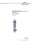
Operating instructions - Translation of the original - Double seat valve Typ: 567x 17.10.12 EPDM, HNBR KIESELMANN GmbH Paul-Kieselmann-Str.4-10 D - 75438 Knittlingen +49 (0) 7043 371-0Fax: +49 (0) 7043 371-125 www.kieselmann.de[email protected] 1. List of contents 1. List of contents ..............................................................................................................................2 2. Information for your safety.............................................................................................................3 3. Marking of security instructions in the operating manual ..............................................................3 4. Safety instructions .........................................................................................................................4 4.1 Field of application .............................................................................................................4 4.2 General safety instructions ................................................................................................4 4.3 General notes ....................................................................................................................4 5. Function.........................................................................................................................................4 5.1 Functional description ........................................................................................................4 6. Installation informations.................................................................................................................5 6.1 Installation instructions.......................................................................................................5 6.2 Welding guidelines .............................................................................................................5 7. Maintenance..................................................................................................................................5 7.1 Maintenance ......................................................................................................................5 7.2 Cleaning flow rate ..............................................................................................................5 8. Technical data ...............................................................................................................................6 9. Control system - and interrogation system ....................................................................................6 9.1 Special features valve control -optional- ............................................................................6 9.2 Proximity switch mounting set -optional-............................................................................6 10. Pneumatic valve actuation ............................................................................................................7 11. Disassembly and Assembly ..........................................................................................................8 11.1 Disassembly.......................................................................................................................8 11.2 Removing in product contact wearing parts - DN25...........................................................8 11.3 Assemble ...........................................................................................................................8 11.4 Removing in product contact wearing parts - DN40-DN150 ..............................................9 11.5 Assembly 9 12. Dimensions................................................................................................................................. 10 12.1 Size measurement table ................................................................................................. 10 12.2 Dimensioned drawing ..................................................................................................... 10 13. Drawings .................................................................................................................................... 11 13.1 Double seat valve Type 567x.......................................................................................... 11 13.2 Valve insert DN25 / 1INCH ............................................................................................. 12 13.3 Valve insert DN40 - DN150 / 1½ - 4INCH....................................................................... 13 14. Manufacturing............................................................................................................................. 14 14.1 Structure of Article number ............................................................................................. 14 15. Spare parts list - Double seat valve Type 567x, DN 25 / 1inch (1.4404 / AISI316L) ................ 15 15.1 Spare parts list - Valve insert Type 5670, DN 25 / 1INCH ............................................. 15 15.2 Seal kits - Double seat valve Type 567x, DN 25 / 1INCH .............................................. 16 16. Spare parts list Double seat valve Type 567x, DN 40 - 150 / DN1 - 4INCH (1.4404 / AISI316L) .. 17 16.1 16.2 Spare parts list - Valve insert Type 5670, DN 40 - 150 / DN 1 - 4INCH......................... 18 Seal kits - Double seat valve Type 567x, DN 40 - 150 / DN 1 - 4INCH .......................... 19 17.10.12 17. Declaration of incorporation ....................................................................................................... 20 Double seat valve Type: 567x 2 2. Information for your safety We are pleased that you have decided for a high-class KIESELMANN product. With correct application and adequate maintenance, our products provide long time and reliable operation. Before installation and initiation, please carefully read this instruction manual and the security advices contained in it. This guarantees reliable and safe operation of this product and your plant respectively. Please note that an incorrect application of the process components may lead to great material damages and personal injury. In case of damages caused by non observance of this instruction manual, incorrect initiation, handling or external interference, guarantee and warranty will lapse! Our products are produced, mounted and tested with high diligence. However, if there is still a reason for complaint, we will naturally try to give you entire satisfaction within the scope of our warranty. We will be at your disposal also after expiration of the warranty. In addition, you will also find all necessary instructions and spare part data for maintenance in this instruction manual. If you don't want to carry out the maintenance by yourself, our KIESELMANN service team will naturally be at your disposal. 3. Marking of security instructions in the operating manual Hints are available in the chapter "safety instructions" or directly before the respective operation instruction. The hints are highlighted with a danger symbol and a signal word. Texts beside these symbols have to be read and adhered to by all means. Please continue with the text and with the handling at the valve only ak 12.1.11 afterwards. Symbol Signal word Meaning DANGER Imminent danger which may cause severe personal injury or death. ATTENTION NOTE Dangerous situation which may cause slight personal injury or material damages. Marks application hints and other information which is particularly useful. Safety informations 3 4. Safety instructions 4.1 Field of application Based upon its functions, the double seat valve is suitable for use in the food and beverages, in pharmaceutical, biotechnological and chemical industries. It is used mainly in combinations with several other double seat valves for the purpose of emptying and filling containers with the possibility of connecting several pipes to one tank. ATTENTION • To avoid danger and damage, the fitting must be used in accordance with the safety instructions and technical data contained in the operating instructions. 4.2 General safety instructions DANGER • Danger of crushing or amputating limbs. Do not reach into the valve housing when in pneumatic mode. • When removing the valve or valve components from the system, there is a danger of injury from escaping liquids or gases. Only dismantle when you are absolutely sure that the system is depressurized and free of liquids and gases. • Danger of scalding and burns to parts of your body from liquids escaping from the leakage drain. The splash protection fixtures must always be attached to the leakage drain. • The actuation can be dismantled. Danger of injury by prestressed pressure spring. Observe separate installation instructions. • We recommend having the manufacturer do the maintenance work required for the actuation. ATTENTION • To avoid air leaking, only use pneumatic connection parts that have an O-ring seal facing the even surface. • When mounting the clamps, the max. torque must not be exceeded (see Technical data). • Steps should be taken to ensure that no external forces are exerted on the fitting. 4.3 General notes NOTE All data are in line with the current state of development. Subject to change as a result of technical progress. 5. Function 5.1 Functional description ak 12.1.11 The valve is opened from bottom to top by means of control air, and is closed from top to bottom by means of spring power without any loss of product. The upper and lower valve chambers are separated during infeed in a leak-proof fashion with two, independently closed valve discs when different media flow through the valve. Leakage which occurs due to damaged valve disc seals is discharged into the atmosphere without pressure via the leakage outlet (fig. 9 /page 12 resp. fig. 10 /page 13). Double seat valve Type: 567x 4 6. Installation informations 6.1 Installation instructions The valve must be installed vertically with the actuator at the upwards. Liquid must be able to flow freely from the valve housing. 6.2 Welding guidelines Sealing elements integrated in weld components must generally be removed prior to welding. • To prevent damage, welding should be undertaken by certified personnel (EN287). • Use the TIG (tungsten inert gas) welding process. NOTE Impurities can cause damage to the seals. Clean inside areas prior to assembly. 7. Maintenance 7.1 Maintenance The maintenance intervals depend on the operating conditions • temperature, temperature-intervals • medium and cleaning medium • pressure and opening frequency We recommend replacing the seals every 1 years. The user, however should establish appropriate maintenance intervals according to the condition of the seals. NOTE EPDM; Viton; K-flex; NBR; HNBR Silicone Thread Lubricant recommendation Klüber Paraliq GTE703* Klüber Sintheso pro AA2* Interflon Food* *) It is only permitted to use approved lubricants, if the respective fitting is used for the production of food or drink. Please observe the relevant safety data sheets of the manufacturers of lubricants. 7.2 Cleaning Cleaning of the housing is performed with the pipe cleaning system. As part of the cleaning program, the leakage chamber and the drain pipe can be cleaned by cycling the valve discs. The valve disc shaft is also cleaned when the upper valve disc is cycled. Alternatively, the leakage chamber and the shaft of the upper valve disc can be cleaned by means of the external rinsing connection (ESP). For cleaning the shaft, the upper valve disc has to be lifted. 7.3 Cleaning flow rate Leakage chamber - Cleaning parameters* Cleaning step Aerate valve disc DIN INCH Pre-Rinse Wash 80°C Intermediate rinse Acid 3 x 5 sec. 2 x 5 sec. 3 x 5 sec. Final rinse 2 x 5 sec. Cleaning flow rate - clocking at the top or at the bottom (m³/h /3bar) Nominal diameter DN 25 40 50 65 80 100 125 150 1 1½ 2 2½ 3 4 - clocking at top 3,5 4,0 4,0 5,0 6,0 7,5 9,0 14,5 clocking at bottom 2,0 2,5 2,5 3,0 3,0 4,5 6,0 9,0 ak 12.1.11 *.Recommended for the Beverage Industry Double seat valve Type: 567x 5 8. Technical data Model: Double seat valve Valve size: DIN: INCH: Connection: DN25 - DN150 DN1 - DN4 Welding end DIN11850 series 2 Temperature range: • Ambient temperature: • Product temperature: • Sterilization temperature: Operations pressure: DIN: INCH: Pressure resistance: +4° - +45°C +0° - +95°C medium dependent +140°C short time (30min) DN25 - 100 = max. 10 bar DN125 - 150 = max. 6 bar DN1 - DN4 = max. 10 bar 40 bar Vacuum: 1,5 - 10-6 mbar x L/S (test pressure 0,5mbar) Control air pressure: 5,5 - 8,0 bar Quality of control air: ISO 8573-1 : 2001 quality class 3 Material: in product contact not in product contact Stainless steel: 1.4404 / AISI316L 1.4301 / AISI304 Surfaces: RA 0,8µm e-pol. metallic bright, e-pol. EPDM (FDA) HNBR (FDA) NBR Seals: Tightening moment: DIN INCH 25 1 15 Retaining clamp: nominal diameter 40 50 65 80 100 125 1½ 2 2½ 3 4 15 15 25 25 55 65 DIN INCH 25 1 26 26 16 16 40 1½ 50 55 26 24 Torque in Nm KV-value (m³/h): Direction of flow: transition-flow at top transition-flow at bottom from bottom to top from top to bottom nominal diameter 50 65 80 2 2½ 3 95 150 240 100 155 250 45 72 98 43 67 93 100 4 380 390 155 150 125 580 590 245 240 150 65 150 940 940 370 330 9. Control system - and interrogation system 9.1 Special features valve control -optional- Optionally, modular valve control systems can be installed to the actuator for reading and actuating valve positions. The standard version is a closed system with SPS or ASI-bus switch-on electronics, and integrated 3/2-way solenoid valves. For tough operating conditions we recommend employing a stainless steel hood. 9.2 Proximity switch mounting set -optional- ak 12.1.11 For the acquisition of the valve positions over inductive initiators, a limit switch support is mounted on the actuation. The enquiry takes place over the position of the piston rod. Double seat valve Type: 567x 6 10. Pneumatic valve actuation Pneum. control Pneum. control Valve function ➟ with integrated (MV) in control unit ➟ with external (MV) Valve stroke valve “OPEN“ control air feed P ➟ MV1 ➟ P1/LA1 control air feed ext.MV1 ➟ LA1 Valve stroke valve “CLOSED“ de-aeration P1/LA1 ➟ MV1 ➟ R de-aeration LA1 ➟ ext.MV1 (fig. 1 /page 7) Lower seat lift Upper seat lift (fig. 2 /page 7) valve is closing by spring valve is closing by spring OPEN = control air feed P ➟ MV2 ➟ P2/LA2 OPEN = control air feed ext.MV2 ➟ P ➟ LA2 CLOSE = de-aeration P2/LA2 ➟ MV2 ➟ R CLOSE = de-aeration LA2 ➟ P ➟ ext.MV2 OPEN = control air feed P ➟ MV3 ➟ P3/LA3 OPEN = control air feed ext.MV3 ➟ LA3 CLOSE = de-aeration P3/LA3 ➟ MV3 ➟ R CLOSE = de-aeration LA3 ➟ ext.MV3 with control unit and solenoid valve pneum. control external MV = solenoid valve MV1 = valve stroke MV2 = lower seat lift MV3 = upper seat lift R = de-aeration, sound absorber P = compressed-air inlet (control unit) LA = compressed-air inlet (actuation) S = slide switch - manual control (solenoid valves) E = proximity switch M12x1 H = proximity switch mount. ak 12.1.11 fig. 1 fig. 2 Double seat valve Type: 567x 7 11. Disassembly and Assembly 11.1 Disassembly ➣Assembling tool kit NW Article no.: 25-65 5670.065.100-000 80-100 5670.100.100-000 125-150 5670.150.100-000 socket spanner M1 eccentric socket M2 NOTE All threaded joint have right-hand thread. Unscrew and remove control air, steam i.e. cleaning lines and electrical lines, complete proximity switch mounting or control head. • Unscrew the upper retaining clamp (3). • Remove the pneumatic valve insert, with the insert (5), the upper seal (D1) and the upper bearing bush (4) along from the top of the housing (1). • Unscrew the lower retaining clamp (3). • Remove the housing bottom (2) with the lower insert (5), the seal (D1) and the lower bearing bush (4). 11.2 Removing in product contact wearing parts - DN25 We recommend to use for the assembly / disassembly the assembling tool kit. (Stock number see Tab. Assembling tool kit) eccentric ring M3 • Unscrew the nut (11) and revove the disc (10). hook wrench M4 • Separate the lower piston (6) from the upper piston (7) in axial direction. ➣ Piston upper • Take off the split washer (13). socket spanner M5 • Unsrew the hexagon nut (14). • Push the lantern (15) in direction ‘X‘ until the hole (B1) is freely visible (fig. 9 /page 12 ). mounting plate M6 • Place the hook spanner in the bore hole (B1) and screw out the upper piston (7) at the top with the mounting plate (see fig. 3 /page 8). • Push off the insert (5), the upper seal (D1) and the upper bearing bush (4) of the piston (7) against direction ‘X‘. • Remove the valve lift stop (16) upwards. • Remove the seals: Item.(D1); (D2)(4x); (D4)(2x); (D5); (D8); (D9); (D10). fig. 3 11.3 Assemble Assemble in reverse order. Thoroughly clean and slightly lubricate mounting areas and running surfaces. ➣ Assembly - seals item (D4) (2x) • Slide the seal onto the groove. • Place rod of approx. diameter 2 between the seal and groove in the direction of the axis. • Remove the twist of the seal by repeated 360° rotations of the rod between seal and groove if necessary. • Alternately press and roll the seal into the groove with round body. ak 12.1.11 NOTE • Fit valve insert carefully into the casing. When fitting the valve insert and running surfaces onto the piston, do not damage. • Always replace the self-locking nut (11) by a new one after unscrewing and secure it with removeable screw retention e.g. Loctite 243. • Check valve functions by manually activating the 3/2-way solenoid valves after assembly! Double seat valve Type: 567x 8 11.4 Removing in product contact wearing parts - DN40-DN150 ➣Assembling tool kit NW Article no.: 25-65 5670.065.100-000 80-100 5670.100.100-000 125-150 5670.150.100-000 socket spanner M1 • • • • • eccentric socket M2 • eccentric ring M3 hook wrench M4 • • • • socket spanner M5 • mounting plate M6 • • • • We recommend to use for the assembly / disassembly the assembling tool kit. (Stock number see Tab. Assembling tool kit) Unscrew the lock nut (11) and remove the disc ➣ Piston lower (10). Separate the lower piston (6) from the upper piston (7) in axial direction. Take off the split washer (13). Clamp the mounting plate into the vice. Position the piston plate lower (9) about the two holes (B2) in the retention pin (see fig. 4 /page 9). Position the mounting lever M5 into the slot (E) (fig. 4 /page 9) and unscrew the piston (6) from the lower piston plate (9). Remove seal (D4) and O-Ring (D6). Unscrew hexagon screw (14)(4x). Push lantern (15) in direction “X“ until the hole (B1) is freely visible (fig. 10 /page 13). Unscrew the upper piston (7) about the holes (B3) and the retention pin. Counter with the hook wrench M4 at the hole (B1) (fig. 5 /page 9). fig. 4 Push off the insert (5), the upper seal (D1) and the ➣ Piston upper upper bearing bush (4) of the piston (7) against direction ‘X‘ (fig. 10 /page 13 ). Unscrew the upper piston (7) with the socket spanner M1 from the upper piston plate (8). Remove seal (D4) and the O-Rings (D3) and (D5). Dismount the Valve lift stop (16) in direction “X“. Dismantle the seals: Item.(D2)(4x), Item.(D8)(2x), Item.(D9), Item.(D10) 11.5 Assembly • Assemble in reverse order. • Thoroughly clean and slightly lubricate mounting areas and running surfaces. NOTE • Fit valve insert carefully into the casing. When fitting the valve insert and running surfaces onto the piston, do not damage. • Always replace the hexagon lock nut (11) by a new one after unscrewing. • Check valve functions by manually activating the 3/2-way solenoid valves after assembly. ➣ Assembly - seals item (D4) (2x) ak 12.1.11 • Screw in piston plate (8) resp. (9) without the seal (D4) to the metal limit stop in the piston (6) resp. (7) and make a coloured mark (fig. 6 /page 9). • Screw out the piston plate (8) resp. (9) of the piston (6) resp. (7). • Push the seal (D4) into the piston (6) resp. (7) and screw the piston plate (8) resp. (9) into the pistons (6) resp. (7) by hand. • Position the eccentric ring (M3) on the seal (D4) (fig. 5 /page 9). • Clamp the mounting plate into the vice and fix the piston plate (8) resp. (9) (see fig. 4 /page 9 resp. fig. 5 /page 9). • Position the socket spanner M1 resp. M5 and screw the piston (6) resp. (7) up to the final limit mark (fig. 6 /page 9). fig. 5 ➣ Mark fig. 6 Double seat valve Type: 567x 9 12. Dimensions 12.1 Size measurement table DIN INCH DIN D1 INCH DIN D2 INCH DIN D3 INCH 25 1 40 1½ 125 - 150 - ø 29x1,5 ø 41x1,5 ø 53x1,5 ø 70x2 ø 85x2 ø 104x2 ø 129x2 ø 25,4x1,65 ø 38,1x1,65 ø 50,8x1,65 ø 63,5x1,65 ø 76,2x1,65 ø 101,6x2,11 - ø 154x2 - ø 29x1,5 ø 41x1,5 ø 53x1,5 ø 70x2 ø 85x2 ø 104x2 ø 129x2 ø 25,4x1,65 ø 38,1x1,65 ø 50,8x1,65 ø 63,5x1,65 ø 76,2x1,65 ø 101,6x2,11 - ø 154x2 - ø 128 ø 128 ø 128 ø 128 50 2 ø 128 ø 128 65 2½ ø 128 ø 128 80 3 ø 160 ø 160 100 4 ø 160 ø 160 ø 230 - ø 230 - 260 260 320 - 345 - 264 264,7 315 - 337 - 125 122 150 - 175 - 560 560 615 - 628 - 232 - - - - Standard rinsing connection: screwed socket DN15 DIN11851 D4 - Rinsing connection: M14x1,5 with cutting ring union for tube 8x1 170 170 210 230 DIN 150 L1 INCH 150 170 170 210 230 118 132 154 181 228 DIN L2 INCH 112,1 127,4 151,3 189,1 223,4 59 72 87 106 DIN 46 L3 INCH 42 56 68,5 81 98 448 447 446 464 531 DIN L4 INCH 448 447 446 464 531 172 192,5 DIN L5 INCH size when completed with control head L6 DIN INCH DIN without control head L6 INCH DIN with control head L7 INCH DIN without control head L7 INCH 600 600 600 600 630 630 680 680 790 790 860 860 960 - 1015 - 590 590 590 590 620 620 670 670 780 780 850 850 950 - 1005 - - - - 953 - 1079 - 1184 - - - - - - 818 - 944 - 1049 - - - 12.2 Dimensioned drawing ak 12.1.11 fig. 7 Double seat valve Type: 567x 10 13. Drawings 13.1 Double seat valve Type 567x A1 = Control head A2 = Proximity switch mount. VE = Valve insert 1 = Valve housing S-S SS-S S-SS SS-SS 2a = Housing bottom 2b = Housing bottom with rinsing connection 3 = Retaining clamp 4 = Bearing bush 5 = Housing insert 15a = Lantern 15b = Lantern with rinsing connection 21 = Screwed socket D1 = Seal D2 = O-Rings D11 = O-Rings D12 = O-Rings ak 12.1.11 fig. 8 Double seat valve Type: 567x 11 13.2 Valve insert DN25 / 1INCH 1) - 2) - 3) Rtaining clamp 4) Bearing bush 5) Housing insert 6) Piston lower 7) Piston upper 8) - 9) - 10) Disc 11) Hexagon nut 12) Plain bearing 13) Split washer 14) Hexagon screw 15) Lantern 16) Valve lift stop 17) pneum. actuator 18) Position indication red 19) O-Ring 20) Screwed cap Seal kit D1) Seal (2x) D2) O-Ring (4x) D3) - D4) Seal (2x) D5) O-Ring D6) - D7) Headless pin D8) O-Ring (2x) D9) O-Ring D10) O-Ring B = Bore E = Slot X = Leakage tell taue IG = Puls generator M = Magnets G1 = Lock nut high strength (e.g. Loctite 2701) LA1 = Main valve lift LA2 = Lower seat lift LA3 = Upper seat lift Y = Detail ak 12.1.11 fig. 9 Double seat valve Type: 567x 12 13.3 Valve insert DN40 - DN150 / 1½ - 4INCH 1) - 2) - 3) Rtaining clamp 4) Bearing bush 5) Housing insert 6) Piston lower 7) Piston upper 8) Piston plate upper 9) Piston plate lower 10) Disc 11) Hexagon nut 12) Plain bearing 13) Split washer 14) Hexagon screw 15) Lantern 16) Valve lift stop 17) pneum. actuator 18) Position indication red 19) O-Ring 20) Screwed cap Seal kit D1) Seal (2x) D2) O-Ring (4x) D3) O-Ring D4) Seal (2x) D5) O-Ring D6) O-Ring D7) Headless pin D8) O-Ring (2x) D9) O-Ring D10) O-Ring B = Bore E = Slot X = Leakage tell taue IG = Puls generator M = Magnets G1 = Lock nut high strength (e.g. Loctite 2701) LA1 = Main valve lift LA2 = Lower seat lift LA3 = Upper seat lift Y = Detail ak 12.1.11 fig. 10 Double seat valve Type: 567x 13 14. Manufacturing 14.1 Structure of Article number 5674 050 730 - 041 Material in product contact / Exterior finish / Interrogation system Material seals in product contact / Construction modifications Valve size Housing type Product type Product type Double seat valve Type 567x Housing type 5670 5671 SS-S 5672 S-S 5673 S-SS 5674 SS-SS Valve without housing Valve size DN = Nominal diameter DIN 025 = DN25 040 = DN40 INCH 026 = DN1 050 = DN50 065 = DN65 080 = DN80 100 = DN100 125 = DN125 150 = DN150 038 = DN1½ 051 = DN2 064 = DN2½ 076 = DN3 101 = DN4 - - Material seal / Construction modifications Material seals in product contact: EPDM, HNBR, NBR, Viton, Silikon, k-flex Construction modifications: external rinsing connection upper / lower 020 - 1.4301/1.4307 AISI304/307 - bright turned 040 - 1.4301/1.4307 AISI304/307 - bright turned 021 - 1.4301/1.4307 AISI304/307 - E-polished 041 - 1.4301/1.4307 AISI304/307 - E-polished 022 - 1.4301/1.4307 AISI304/307 - unpolished, glass-bead blasted 042 - 1.4301/1.4307 AISI304/307 - unpolished, glass-bead blasted Interrogation system Article number Control System or Interrogation System (A1, A2) 56xx DN xxx -041 Valve without Control- or Interrogation System 56xx DN xxx -750 Valve with Sensor mounting set (5630 005 000-020) 56xx DN xxx -6xx Control head ASi-Bus for Double seat valves 56xx DN xxx -K6xx Control head KI-Top ASi-Bus for Double seat valves 56xx DN xxx -5xx Control head SPS for Double seat valves 56xx DN xxx -K5xx Control head KI-Top SPS for Double seat valves DN 17.10.12 Material in product contact / Exterior finish - nominal diameter e.g. 5674 050 730-041 Double seat valve Type: 567x 14 15. Spare parts list - Double seat valve Type 567x, DN 25 / 1inch (1.4404 / AISI316L) Housing type Standard SS - S S-S S - SS SS - SS SS - S S-S S - SS SS - SS ext. rinsing connection upper SS - S S-S S - SS SS - SS SS - S S-S S - SS SS - SS Seal EPDM HNBR EPDM HNBR VE Valve insert Article number 5671 DN 130 - xxx 5672 DN 130 - xxx 5673 DN 130 - xxx 5674 DN 130 - xxx 5671 DN 420 - xxx 5672 DN 420 - xxx 5673 DN 420 - xxx 5674 DN 420 - xxx 5671 DN 760 - xxx 5672 DN 760 - xxx 5673 DN 760 - xxx 5674 DN 760 - xxx 5671 DN 770 - xxx 5672 DN 770 - xxx 5673 DN 770 - xxx 5674 DN 770 - xxx Seal kit 5670 DN 130-041 5670 025 130-000 5670 DN 420-041 5670 025 420-000 5670 DN 760-041 5670 025 769-000 5670 DN 770-041 5670 025 779-000 rinsing connection: M14x1,5 with cutting ring union for tube 8x1 SS - S 5671 DN 762 - xxx S-S 5672 DN 762 - xxx EPDM 5670 DN 762-041 5670 025 769-000 S - SS 5673 DN 762 - xxx SS - SS 5674 DN 762 - xxx SS - S 5671 DN 772 - xxx S-S 5672 DN 772 - xxx HNBR 5670 DN 772-041 5670 025 779-000 S - SS 5673 DN 772 - xxx SS - SS 5674 DN 772 - xxx DDN- Nominal diameter e.g. 5674 050 730-041 xxx - Material in product contact / Exterior finish / Interrogation system (see Tab. Interrogation system) S - Welding end Item 2 3 4 5 D1 D2 Designation Housing bottom Retaining clamp (2x) Bearing bush lower Housing insert lower Seal (included in seal kit) O-Ring (2x) (included in seal kit) Material AISI303 AISI304 PTFE AISI316L EPDM HNBR EPDM HNBR Item.1 Housing DIN / INCH 5621 DN 001-041 / 5661 DN 001-041 5622 DN 001-041 / 5662 DN 001-041 5623 DN 001-041 / 5663 DN 001-041 5624 DN 001-041 / 5664 DN 001-041 5621 DN 001-041 / 5661 DN 001-041 5622 DN 001-041 / 5662 DN 001-041 5623 DN 001-041 / 5663 DN 001-041 5624 DN 001-041 / 5664 DN 001-041 5621 DN 001-041 / 5661 DN 001-041 5622 DN 001-041 / 5662 DN 001-041 5623 DN 001-041 / 5663 DN 001-041 5624 DN 001-041 / 5664 DN 001-041 5621 DN 001-041 / 5661 DN 001-041 5622 DN 001-041 / 5662 DN 001-041 5623 DN 001-041 / 5663 DN 001-041 5624 DN 001-041 / 5664 DN 001-041 5621 DN 001-041 / 5661 DN 001-041 5622 DN 001-041 / 5662 DN 001-041 5623 DN 001-041 / 5663 DN 001-041 5624 DN 001-041 / 5664 DN 001-041 5621 DN 001-041 / 5661 DN 001-041 5622 DN 001-041 / 5662 DN 001-041 5623 DN 001-041 / 5663 DN 001-041 5624 DN 001-041 / 5664 DN 001-041 DN25 / 1INCH 5671 025 008-220 2122 065 100-020 5622 050 006-053 5672 025 004-040 5622 050 010-069 5622 050 010-050 2304 069 026-159 2304 069 026-050 15.1 Spare parts list - Valve insert Type 5670, DN 25 / 1INCH Item VE Designation Material Valve insert (a) EPDM HNBR Valve insert (b) EPDM ext. rinsing connection upper HNBR Valve insert (c) EPDM rinsing connection: M14x1,5 with cutting ring union for HNBR Standard VE VE 4 5 6 7 8 9 10 11 12 13 14 15 17.10.12 16 17 18 19 20 21 LA1 LA3 tube 8x1 Bearing bush upper Housing insert upper Piston lower Piston upper Disc Hexagon nut Plain bearing Split washer Hexagon screw Lantern Valve insert (a) Lantern compl. - Valve insert (b) Lantern compl. - Valve insert (c) Valve lift stop Pneum. actuator Position indication red O-Ring Screwed cap Screwed socket One-way restricter Rapid action hose coupling PTFE AISI316L AISI316L AISI316L AISI304 AISI304 XMS AISI304 AISI304 AISI304 AISI304 AISI304 AISI303 AISI304 PVC NBR AISI303 AISI303 - DN25 1INCH 5670 025 130-041 5670 025 420-041 5670 026 130-041 5670 026 420-041 5670 025 760-041 5670 025 770-041 5670 026 760-041 5670 026 770-041 5670 025 762-041 5670 025 772-041 5670 026 762-041 5670 026 772-041 5622 050 006-053 5672 025 004-040 5671 025 005-040 5622 025 003-040 8071 064 001-020 8113 006 000-020 8050 015 007-156 8140 006 001-020 8106 008 016-020 5624 040 008-021 5624 040 515-021 5624 040 517-021 5622 025 009-220 5620 065 000-021 5622 100 058-151 2304 012 020-055 5622 100 071-220 5624 065 514-020 8218 001 020-000 8217 000 004-000 Double seat valves Type: 567x 15 15.2 Seal kits - Double seat valve Type 567x, DN 25 / 1INCH Item D1 D2 D3 D4 D5 D6 D7 D8 D9 D10 D11 11 Item 17.10.12 D1 D2 D3 D4 D5 D6 D7 D8 D9 D10 D11 11 Designation Seal kit EPDM (A) Seal kit EPDM (B) - rinsing connection upper Material EPDM EPDM DN25 / 1INCH 5670 025 130-000 5670 025 769-000 Seal (2x) O-Ring (4x) O-Ring (2x) O-Ring Headless pin O-Ring (2x) O-Ring O-Ring O-Ring (seal kit B) Hexagon nut EPDM EPDM EPDM EPDM AISI304 EPDM EPDM HNBR EPDM AISI304 5622 050 010-069 2304 069 026-159 2304 047 035-159 2304 041 035-159 8112 006 040-020 2304 036 035-159 2304 047 035-159 2304 042 025-055 2304 014 020-170 8113 006 000-020 Designation Seal kit HNBR (A) Seal kit HNBR (B) - rinsing connection upper Material HNBR HNBR DN25 / 1INCH 5670 025 420-000 5670 025 779-000 Seal (2x) O-Ring (4x) O-Ring (2x) O-Ring Headless pin O-Ring (2x) O-Ring O-Ring O-Ring (seal kit B) Hexagon nut HNBR HNBR HNBR HNBR AISI304 EPDM EPDM NBR EPDM AISI304 5622 050 010-050 2304 069 026-050 2304 047 035-157 2304 041 035-157 8112 006 040-020 2304 036 035-159 2304 047 035-159 2304 042 025-055 2304 014 020-170 8113 006 000-020 Double seat valves Type: 567x 16 16. Spare parts list Double seat valve Type 567x, DN 40 - 150 / DN1 - 4INCH (1.4404 / AISI316L) Housing type Seal Article number VE Valve insert Item.1 Housing DIN / INCH Seal kit Standard Item. 2 Housing bottom 5671 DN 730-xxx 5672 DN 730-xxx 5673 DN 730-xxx 5670 DN 730-041 5670 DN 739-000 5674 DN 730-xxx 5671 DN 720-xxx 5672 DN 720-xxx 5670 DN 720-041 5670 DN 729-000 5673 DN 720-xxx 5674 DN 720-xxx AISI316L 5621 DN 001-041 / 5661 DN 001-041 5622 DN 001-041 / 5662 DN 001-041 5623 DN 001-041 / 5663 DN 001-041 5624 DN 001-041 / 5664 DN 001-041 5621 DN 001-041 / 5661 DN 001-041 5622 DN 001-041 / 5662 DN 001-041 5623 DN 001-041 / 5663 DN 001-041 5624 DN 001-041 / 5664 DN 001-041 5671 DN 760-xxx 5672 DN 760-xxx 5673 DN 760-xxx 5670 DN 760-041 5670 DN 769-000 5674 DN 760-xxx 5671 DN 770-xxx 5672 DN 770-xxx 5670 DN 770-041 5670 DN 779-000 5673 DN 770-xxx 5674 DN 770-xxx 5621 DN 001-041 / 5661 DN 001-041 5622 DN 001-041 / 5662 DN 001-041 5623 DN 001-041 / 5663 DN 001-041 5624 DN 001-041 / 5664 DN 001-041 5621 DN 001-041 / 5661 DN 001-041 5622 DN 001-041 / 5662 DN 001-041 5623 DN 001-041 / 5663 DN 001-041 5624 DN 001-041 / 5664 DN 001-041 5671 DN 008-220 complete with Item 21 and D11 rinsing connection: M14x1,5 with cutting ring union for tube 8x1 SS - S 5671 DN 762-xxx S-S 5672 DN 762-xxx EPDM 5670 DN 762-041 5670 DN 769-000 S - SS 5673 DN 762-xxx 5674 DN 762-xxx SS - SS SS - S 5671 DN 772-xxx S-S HNBR 5672 DN 772-xxx 5670 DN 772-041 5670 DN 779-000 5673 DN 772-xxx S - SS SS - SS 5674 DN 772-xxx 5621 DN 001-041 / 5661 DN 001-041 5622 DN 001-041 / 5662 DN 001-041 5623 DN 001-041 / 5663 DN 001-041 5624 DN 001-041 / 5664 DN 001-041 5621 DN 001-041 / 5661 DN 001-041 5622 DN 001-041 / 5662 DN 001-041 5623 DN 001-041 / 5663 DN 001-041 5624 DN 001-041 / 5664 DN 001-041 5671 DN 008-220 complete with Item 21 and D11 SS - S S-S S - SS SS - SS SS - S S-S S - SS SS - SS EPDM HNBR ext. rinsing connection upper SS - S S-S EPDM S - SS SS - SS SS - S S-S HNBR S - SS SS - SS ext. rinsing connection lower SS - S 5621 DN 001-041 / 5661 DN 001-041 5671 DN 793-xxx 5672 DN 793-xxx 5670 DN 793-041 5670 DN 799-000 5622 DN 001-041 / 5662 DN 001-041 S-S EPDM S - SS 5673 DN 793-xxx 5623 DN 001-041 / 5663 DN 001-041 SS - SS 5674 DN 793-xxx 5624 DN 001-041 / 5664 DN 001-041 SS - S 5621 DN 001-041 / 5661 DN 001-041 5671 DN 792-xxx S-S 5672 DN 792-xxx 5622 DN 001-041 / 5662 DN 001-041 HNBR 5670 DN 792-041 5670 DN 798-000 S - SS 5673 DN 792-xxx 5623 DN 001-041 / 5663 DN 001-041 SS - SS 5674 DN 792-xxx 5624 DN 001-041 / 5664 DN 001-041 DN = Nominal diameter e.g. 5674 050 730-041 xxx = Material in product contact / Exterior finish / Interrogation system (see Tab. Interrogation system) S = Welding end 17.10.12 Item Designation Material DN40 1½INCH DN50 2INCH DN65 2½INCH DN80 3INCH DN100 4INCH AISI303 5671 DN 008-220 5676 DN 023-220 complete with Item 21 and D11 DN125 - DN150 - 3 Retaining clamp (2x) AISI304 2122 065 100-020 2122 065 100-020 2122 080 100-020 2122 115 100-020 2122 125 100-020 2122 150 100-020 2122 200 100-020 4 Bearing bush lower PTFE 5622 050 006-053 5622 050 006-053 5622 065 006-053 5622 080 006-053 5622 100 006-053 5622 125 006-053 5622 150 006-053 5 Housing insert lower AISI316L 5622 050 005-040 5622 050 005-040 5622 065 005-040 5622 080 005-040 5622 100 005-040 5622 125 005-040 5622 150 005-040 D1 Seal (included in seal kit) EPDM HNBR 5622 050 010-069 5622 050 010-069 5622 065 010-069 5622 080 010-069 5622 100 010-069 5622 125 010-069 5622 150 010-069 5622 050 010-050 5622 050 010-050 5622 065 010-050 5622 080 010-050 5622 100 010-050 5622 125 010-050 5622 150 010-050 D2 O-Ring (2x) (included in seal kit) EPDM HNBR 2304 069 026-159 2304 069 026-159 2304 082 026-159 2304 098 035-159 2304 117 035-159 2304 142 035-159 2304 177 035-170 2304 069 026-050 2304 069 026-050 2304 082 026-050 2304 098 035-050 2304 117 035-050 2304 142 035-050 2304 177 035-050 Double seat valve Type: 567x 17 16.1 Spare parts list - Valve insert Type 5670, DN 40 - 150 / DN 1 - 4INCH Item VE Designation Valve insert (a) - DIN - DN40 1½INCH DN50 2INCH DN65 2½INCH DN80 3INCH DN100 4INCH DN125 - DN150 - EPDM HNBR 5670 040 730-041 5670 050 730-041 5670 065 730-041 5670 080 730-041 5670 100 730-041 5670 125 730-041 5670 150 730-041 5670 040 720-041 5670 050 720-041 5670 065 720-041 5670 080 720-041 5670 100 720-041 5670 125 720-041 5670 150 720-041 EPDM HNBR 5670 040 760-041 5670 050 760-041 5670 065 760-041 5670 080 760-041 5670 100 760-041 5670 125 760-041 5670 150 760-041 5670 040 770-041 5670 050 770-041 5670 065 770-041 5670 080 770-041 5670 100 770-041 5670 125 770-041 5670 150 770-041 EPDM HNBR 5670 040 762-041 5670 050 762-041 5670 065 762-041 5670 080 762-041 5670 100 762-041 5670 125 762-041 5670 150 762-041 5670 040 772-041 5670 050 772-041 5670 065 772-041 5670 080 772-041 5670 100 772-041 5670 125 772-041 5670 150 772-041 EPDM HNBR 5670 040 793-041 5670 050 793-041 5670 065 793-041 5670 080 793-041 5670 100 793-041 5670 125 793-041 5670 150 793-041 5670 040 792-041 5670 050 792-041 5670 065 792-041 5670 080 792-041 5670 100 792-041 5670 125 792-041 5670 150 792-041 EPDM HNBR 5670 038 730-041 5670 051 730-041 5670 064 730-041 5670 076 730-041 5670 101 730-041 5670 038 720-041 5670 051 720-041 5670 064 720-041 5670 076 720-041 5670 101 720-041 - EPDM HNBR 5670 038 760-041 5670 051 760-041 5670 064 760-041 5670 076 760-041 5670 101 760-041 5670 038 770-041 5670 051 770-041 5670 064 770-041 5670 076 770-041 5670 101 770-041 - EPDM HNBR 5670 038 762-041 5670 051 762-041 5670 064 762-041 5670 076 762-041 5670 101 762-041 5670 038 772-041 5670 051 772-041 5670 064 772-041 5670 076 772-041 5670 101 772-041 - EPDM HNBR 5670 038 793-041 5670 051 793-041 5670 064 793-041 5670 076 793-041 5670 101 793-041 5670 038 792-041 5670 051 792-041 5670 064 792-041 5670 076 792-041 5670 101 792-041 - ext. rinsing connection lower 4 Bearing bush upper PTFE 5622 050 006-053 5622 050 006-053 5622 065 006-053 5622 080 006-053 5622 100 006-053 5622 125 006-053 5622 150 006-040 5 Housing insert upper AISI316L 5622 050 005-040 5622 050 005-040 5622 065 005-040 5622 080 005-040 5622 100 005-040 5622 125 005-040 5622 150 005-040 6 Piston lower -valve insert (a),(b),(c) Piston lower -valve insert (d) AISI316L 5621 040 005-040 5671 050 005-040 5671 065 005-040 5671 080 005-040 5671 100 005-040 5671 125 005-040 5671 150 005-040 5676 040 023-040 5676 050 023-040 5676 065 023-040 5676 080 023-040 5676 100 023-040 5676 125 023-040 5676 150 023-040 7 Piston upper AISI316L 5621 040 007-040 5621 050 007-040 5621 065 007-040 5621 080 007-040 5621 100 007-040 5621 125 007-040 5621 150 007-040 8 Piston plate upper AISI316L 5621 050 006-040 5621 050 006-040 5621 065 006-040 5621 080 006-040 5621 100 006-040 5621 125 006-040 5621 150 006-040 9 Piston plate lower AISI316L 5621 040 004-040 5621 050 004-040 5621 065 004-040 5621 080 004-040 5621 100 004-040 5621 125 004-040 5621 150 004-040 10 Disc AISI304 8071 064 001-020 8071 064 001-020 8071 064 001-020 8071 084 001-020 8071 084 001-020 8071 105 001-020 8071 105 001-020 11 Hexagon nut AISI304 8113 006 000-020 8113 006 000-020 8113 006 000-020 8113 008 000-020 8113 008 000-020 8113 010 000-020 8113 010 000-020 12 Plain bearing XMS 8050 015 007-156 8050 015 007-156 8050 015 007-156 8050 020 007-156 8050 020 007-156 8050 020 007-156 8050 020 007-156 13 Split washer AISI304 8140 006 001-020 8140 006 001-020 8140 006 001-020 8072 008 001-020 8072 008 001-020 - 14 Hexagon screw Disc DIN125 AISI304 AISI304 8106 008 016-020 8106 008 016-020 8106 008 016-020 8106 008 016-020 8106 008 016-020 8106 008 025-020 8106 008 025-020 8071 084 001-020 8071 084 001-020 15 Lantern -valve insert (a), (d) Lantern compl. -valve insert (b) Lantern compl. -valve insert (c) AISI304 AISI304 AISI304 5624 040 008-021 5624 050 008-021 5624 065 008-021 5624 080 008-021 5624 100 008-021 5624 125 008-021 5624 150 008-021 5624 040 515-021 5624 050 515-021 5624 065 515-021 5624 080 515-021 5624 100 515-021 5624 125 515-021 5624 150 515-021 5624 040 517-021 5624 050 517-021 5624 065 517-021 5624 080 517-021 5624 100 517-021 5624 125 517-021 5624 150 517-021 16 Valve lift stop AISI303 5622 040 009-220 5622 050 009-220 5622 065 009-220 5622 080 009-220 5622 100 009-220 5622 125 009-220 5622 150 009-220 17 Pneum. actuator AISI304 5620 065 000-021 5620 065 000-021 5620 065 000-021 5620 100 000-021 5620 100 000-021 5620 150 000-021 5620 150 000-021 18 Position indication red PVC 5622 100 058-151 5622 100 058-151 5622 100 058-151 5622 100 058-151 5622 100 058-151 5622 100 058-151 5622 100 058-151 19 O-Ring NBR 2304 012 020-055 2304 012 020-055 2304 012 020-055 2304 012 020-055 2304 012 020-055 2304 012 020-055 2304 012 020-055 20 Screwed cap AISI303 5622 100 071-220 5622 100 071-220 5622 100 071-220 5622 100 071-220 5622 100 071-220 5622 100 071-220 5622 100 071-220 21 Screwed socket AISI303 5624 065 514-020 5624 065 514-020 5624 065 514-020 5624 100 514-020 5624 100 514-020 5624 150 514-020 5624 150 514-020 LA1 One-way restricter - 8218 001 020-000 8218 001 020-000 8218 001 020-000 8218 001 020-000 8218 001 020-000 8218 001 020-000 8218 001 020-000 LA3 Rapid action hose coupling - 8217 000 004-000 8217 000 004-000 8217 000 004-000 8217 000 004-000 8217 000 004-000 8217 000 004-000 8217 000 004-000 Standard VE Valve insert (b) - DIN ext. rinsing connection upper VE Valve insert (c) - DIN rinsing connection: M14x1,5 with cutting ring union for tube 8x1 VE Valve insert (d) - DIN ext. rinsing connection lower VE Valve insert (a) - INCH Standard VE Valve insert (b) - INCH ext. rinsing connection upper VE Valve insert (c) - INCH rinsing connection: M14x1,5 with cutting ring union for tube 8x1 VE 17.10.12 Material Valve insert (d) - INCH - - Double seat valve Type: 567x 18 16.2 Seal kits - Double seat valve Type 567x, DN 40 - 150 / DN 1 - 4INCH Item Designation Seal kit (A) DN40 1½INCH Material DN50 2INCH DN65 2½INCH DN80 3INCH DN100 4INCH DN125 - DN150 - EPDM 5670 040 739-000 5670 050 739-000 5670 065 739-000 5670 080 739-000 5670 100 739-000 5670 125 739-000 5670 150 739-000 EPDM 5670 040 769-000 5670 050 769-000 5670 065 769-000 5670 080 769-000 5670 100 769-000 5670 125 769-000 5670 150 769-000 Seal kit (C) - rinsing connection lower EPDM 5670 040 799-000 5670 050 799-000 5670 065 799-000 5670 080 799-000 5670 100 799-000 5670 125 799-000 5670 150 799-000 D1 Seal (2x) EPDM 5622 050 010-069 5622 050 010-069 5622 065 010-069 5622 080 010-069 5622 100 010-069 5622 125 010-069 5622 150 010-069 D2 O-Ring (4x) EPDM 2304 069 026-159 2304 069 026-159 2304 082 026-159 2304 098 035-159 2304 117 035-159 2304 142 035-159 2304 177 035-170 D3 O-Ring EPDM 2304 026 015-170 2304 026 015-170 2304 029 015-170 2304 042 020-170 2304 036 020-170 2304 036 020-170 2304 036 020-170 D4 Seal (2x) EPDM 5621 050 010-084 5621 050 010-084 5621 065 010-084 5621 080 010-084 5621 100 010-084 2304 113 053-084 2304 133 053-159 D5 O-Ring EPDM 2304 041 035-159 2304 041 035-159 2304 050 035-159 2304 066 035-159 2304 085 035-159 2304 111 035-084 2304 140 035-159 D6 O-Ring EPDM 2304 038 018-170 2304 038 018-170 2304 048 020-170 2304 057 020-170 2304 076 020-170 2304 092 035-159 2304 108 035-170 D7 Headless pin AISI316L 8112 006 050-040 8112 006 060-040 8112 006 085-040 8112 008 050-040 8112 008 085-040 8112 010 065-020 8112 010 090-040 D8 O-Ring EPDM 2304 036 035-159 2304 036 035-159 2304 036 035-159 2304 041 035-159 2304 041 035-159 2304 041 035-159 2304 041 035-159 D9 O-Ring EPDM 2304 047 035-159 2304 047 035-159 2304 057 035-159 2304 069 035-159 2304 092 035-159 2304 117 035-159 2304 142 035-159 D10 O-Ring NBR 2304 042 025-055 2304 042 025-055 2304 042 025-055 2304 046 025-055 2304 046 025-055 2304 046 025-055 2304 046 025-055 D11 O-Ring (1x) (seal kit B) O-Ring (2x) (seal kit C) EPDM 2304 014 020-170 2304 014 020-170 2304 014 020-170 2304 014 020-170 2304 016 020-170 2304 016 020-170 2304 016 020-170 D12 O-Ring (2x) (only seal kit C) EPDM - 11 Hexagon nut AISI304 8113 006 000-020 8113 006 000-020 8113 006 000-020 8113 008 000-020 8113 008 000-020 8113 010 000-020 8113 010 000-020 - Standard Seal kit (B) - rinsing connection upper Item Designation Seal kit (A) 2304 036 035-159 2304 054 035-159 2304 082 035-159 - DN40 1½INCH Material DN50 2INCH DN65 2½INCH DN80 3INCH - DN100 4INCH - DN125 - DN150 - HNBR 5670 040 729-000 5670 050 729-000 5670 065 729-000 5670 080 729-000 5670 100 729-000 5670 125 729-000 5670 150 729-000 HNBR 5670 040 779-000 5670 050 779-000 5670 065 779-000 5670 080 779-000 5670 100 779-000 5670 125 779-000 5670 150 779-000 Seal kit (C) - rinsing connection lower HNBR 5670 040 798-000 5670 050 798-000 5670 065 798-000 5670 080 798-000 5670 100 798-000 5670 125 798-000 5670 150 798-000 D1 Seal (2x) HNBR 5622 050 010-050 5622 050 010-050 5622 065 010-050 5622 080 010-050 5622 100 010-050 5622 125 010-050 5622 150 010-050 D2 O-Ring (4x) HNBR 2304 069 026-050 2304 069 026-050 2304 082 026-050 2304 098 035-050 2304 117 035-050 2304 142 035-050 2304 177 035-050 D3 O-Ring EPDM 2304 026 015-170 2304 026 015-170 2304 029 015-170 2304 042 020-170 2304 036 020-170 2304 036 020-170 2304 036 020-170 D4 Seal (2x) HNBR 5621 050 010-157 5621 050 010-157 5621 065 010-157 5621 080 010-157 5621 100 010-157 2304 113 053-157 2304 133 053-157 D5 O-Ring HNBR 2304 041 035-157 2304 041 035-157 2304 050 035-157 2304 066 035-157 2304 085 035-157 2304 111 035-157 2304 140 035-157 D6 O-Ring EPDM 2304 038 018-170 2304 038 018-170 2304 048 020-170 2304 057 020-170 2304 076 020-170 2304 092 035-159 2304 108 035-170 D7 Headless pin AISI316L 8112 006 050-040 8112 006 060-040 8112 006 085-040 8112 008 050-040 8112 008 085-040 8112 010 065-020 8112 010 090-040 D8 O-Ring EPDM 2304 036 035-159 2304 036 035-159 2304 036 035-159 2304 041 035-159 2304 041 035-159 2304 041 035-157 2304 041 035-159 D9 O-Ring EPDM 2304 047 035-159 2304 047 035-159 2304 057 035-159 2304 069 035-159 2304 092 035-159 2304 117 035-159 2304 142 035-159 D10 O-Ring NBR 2304 042 025-055 2304 042 025-055 2304 042 025-055 2304 046 025-055 2304 046 025-055 2304 046 025-055 2304 046 025-055 D11 O-Ring (1x) (seal kit B) O-Ring (2x) (seal kit C) EPDM 2304 014 020-170 2304 014 020-170 2304 014 020-170 2304 014 020-170 2304 016 020-170 2304 016 020-170 2304 016 020-170 D12 O-Ring (2x) (only seal kit C) EPDM - 11 Hexagon nut AISI304 8113 006 000-020 8113 006 000-020 8113 006 000-020 8113 008 000-020 8113 008 000-020 8113 010 000-020 8113 010 000-020 - Standard Seal kit (B) 17.10.12 - rinsing connection upper 2304 036 035-159 2304 054 035-159 2304 082 035-159 - - - Double seat valve Type: 567x 19 Declaration of incorporation Translation of the original Manufacturer / authorised representative: KIESELMANN GmbH Paul-Kieselmann-Str. 4-10 75438 Knittlingen Germany Authorised representative, for compiling technical documents: Achim Kauselmann KIESELMANN GmbH Paul-Kieselmann-Str. 4-10 75438 Knittlingen Germany Product name Function pneum. Lift actuators pneum. Rotary actuators Ball valves Butterfly valves Single seat valves Flow control valves Throttle valve Overflow valve Double seat valve Bellow valves Sampling valves Two way valves Tankdome fitting Stroke movement Rotary movement Media cutoff Media cutoff Media cutoff Control of liquefied media Control of liquefied media Definition of fluid pressure Media separation Sampling of liquids Sampling of liquids Media cutoff Prevention of overpressure and vacuum, Tank cleaning The manufacturer hereby states that the above product is considered as an incomplete machine in the sense defined in the Directive 2006/42/EC on Machinery. The above product is exclusively intended to be installed into a machine or an incomplete machine. The said product does not yet conform to all the relevant requirements defined in the Directive on Machinery referred to above for this reason. The specific technical documents listed in Appendix VII, Part B, have been prepared. The Authorized Agent empowered to compile technical documents may submit the relevant documents if such a request has been properly justified. Commissioning of an incomplete machine may only be carried out if it has been determined that the respective machine into which the incomplete machine is to be installed conforms to the regulations set out in the Directive on Machinery referred to above. The above product conforms to the requirements of the directives and harmonized standards specified below: • DIN EN ISO 12100 Safety of machinery Knittlingen, 17. 10. 2012 Klaus Dohle General Director