1
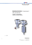
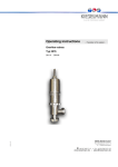
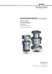
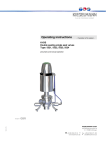
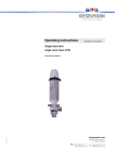
Operating instructions - Translation of the original - Bunging valve Type: 6267 14.4.15 spring loaded KIESELMANN GmbH Paul-Kieselmann-Str.4-10 D - 75438 Knittlingen +49 (0) 7043 371-0Fax: +49 (0) 7043 371-125 www.kieselmann.de[email protected] 1. List of contents 1. List of contents ..............................................................................................................................1 2. General safety instructions ............................................................................................................2 2.1 Information for your safety .................................................................................................2 2.2 Marking of security instructions in the operating manual ...................................................2 2.3 Designated use ..................................................................................................................2 2.4 Personnel ...........................................................................................................................2 2.5 Modifications, spare parts, accessories .............................................................................2 2.6 General instructions ...........................................................................................................2 3. Safety instructions .........................................................................................................................3 3.1 Field of application .............................................................................................................3 3.2 General safety instructions ................................................................................................3 3.3 General notes ....................................................................................................................3 4. Function.........................................................................................................................................3 4.1 General functional description ...........................................................................................3 4.2 Manual operation ...............................................................................................................3 5. Installation informations.................................................................................................................3 5.1 Installation instructions.......................................................................................................3 5.2 Welding guidelines .............................................................................................................3 5.3 Pressure setting .................................................................................................................4 6. Maintenance..................................................................................................................................4 6.1 Maintenance ......................................................................................................................4 6.2 Cleaning .............................................................................................................................4 7. Technical Data ..............................................................................................................................4 8. Disassembly and assembly...........................................................................................................5 8.1 Disassembly.......................................................................................................................5 8.2 Assembly ...........................................................................................................................5 9. Drawing .........................................................................................................................................6 10. Dimensions....................................................................................................................................7 11. Spare parts list ..............................................................................................................................7 12. Blow-off performance chart ...........................................................................................................8 14.4.15 13. Declaration of incorporation ........................................................................................................11 Bunging valve type: 6267 1 2. General safety instructions 2.1 Information for your safety We are pleased that you have decided for a high-class KIESELMANN product. With correct application and adequate maintenance, our products provide long time and reliable operation. Before installation and initiation, please carefully read this instruction manual and the security advices contained in it. This guarantees reliable and safe operation of this product and your plant respectively. Please note that an incorrect application of the process components may lead to great material damages and personal injury. In case of damages caused by non observance of this instruction manual, incorrect initiation, handling or external interference, guarantee and warranty will lapse! Our products are produced, mounted and tested with high diligence. However, if there is still a reason for complaint, we will naturally try to give you entire satisfaction within the scope of our warranty. We will be at your disposal also after expiration of the warranty. In addition, you will also find all necessary instructions and spare part data for maintenance in this instruction manual. If you don't want to carry out the maintenance by yourself, our KIESELMANN service team will naturally be at your disposal. 2.2 Marking of security instructions in the operating manual Hints are available in the chapter "safety instructions" or directly before the respective operation instruction. The hints are highlighted with a danger symbol and a signal word. Texts beside these symbols have to be read and adhered to by all means. Please continue with the text and with the handling at the valve only afterwards. Symbol Signal word Meaning DANGER Imminent danger which may cause severe personal injury or death. ATTENTION Dangerous situation which may cause slight personal injury or material damages. NOTE Marks application hints and other information which is particularly useful. 2.3 Designated use The fitting is designed exclusively for the purposes described below. Using the fitting for purposes other than those mentioned is considered contrary to its designated use. KIESELMANN cannot be held liable for any damage resulting from such use. The risk of such misuse lies entirely with the user. The prerequisite for the reliable and safe operation of the fitting is proper transportation and storage as well as competent installation and assembly. Operating the fitting within the limits of its designated use also involves observing the operating, inspection and maintenance instructions. 2.4 Personnel Personnel entrusted with the operation and maintenance of the tank safety system must have the suitable qualification to carry out their tasks. They must be informed about possible dangers and must understand and observe the safety instructions given in the relevant manual. Only allow qualified personnel to make electrical connections. 2.5 Modifications, spare parts, accessories Unauthorized modifications, additions or conversions which affect the safety of the fitting are not permitted. Safety devices must not be bypassed, removed or made inactive. Only use original spare parts and accessories recommended by the manufacturer. 2.6 General instructions The user is obliged to operate the fitting only when it is in good working order. In addition to the instructions given in the operating manual, please observe the following: • relevant accident prevention regulations • generally accepted safety regulations • regulations effective in the country of installation • working and safety instructions effective in the user's plant. Safety informations 2 3. Safety instructions 3.1 Field of application The bunging valve is primarily intended to be used to hold the pressure of gaseous media in tanks and containers consistently. ATTENTION • To avoid danger and damage, the fitting must be used in accordance with the safety instructions and technical data contained in the operating instructions. 3.2 General safety instructions DANGER • Dismantling the valve or valve assemblies from the plant can cause injuries from fluids or gases flowing out. Dismantle the valve or valve assembly only when the plant has been rendered pressure-less and free of liquid and gas. ATTENTION • Steps should be taken to ensure that no external forces are exerted on the fitting. 3.3 General notes NOTE • All data are in line with the current state of development. Subject of change as a result of technical progress. 4. Function 4.1 General functional description The valve opens against spring force if the set pressure is crossed. It closes if the current pressure drops under the set pressure (see “Blow-off performance chart” page 8). 4.2 Manual operation The manual lifting lever serves to manually actuate the valve. • Short term lifting of the valve takes place by pulling on the spindle (3) via the spherical button (11) and/or the lifting nut (10) in the direction X. This will raise the plate (2) and the medium disperses via outlet B. • For a longer lifting of the valve (e.g. when cleaning), the lifting nut (10) is turned in a clockwise direction to the adjusting nut (9). Now mark the position with a pen/pencil. Unscrew the adjusting nut (9) anticlockwise using 2 complete turns. The plate (2) will be raised and the medium disperses via outlet B. • In order to close the valve, the adjusting nut (9) is turned in an anticlockwise direction using 2 complete turns as far as the mark. Screw the lifting nut (10) anticlockwise as far as the spherical button (11) and tighten. 5. Installation informations 5.1 Installation instructions Fitting position As a general rule, the valve should be installed vertically on connection ‘A’. Performance test After the installation, the working of the valve is checked through manual lifting. For this, pull the spherical button in the direction X (Fig. 2 /page 7). 5.2 Welding guidelines Sealing elements integrated in weld components must generally be removed prior to welding. To prevent damage, welding should be undertaken by certified personnel (EN287). Use the TIG (tungsten inert gas) welding process. 14.4.15 NOTE Impurities can cause damage to the seals. Clean inside areas prior to assembly. Bunging valve type: 6267 3 5.3 Pressure setting The set pressure can be adjusted to scaling in the pressure area by longitudinal positioning of the adjustment nut (9). The longitudinal positioning of the adjustments nut (9) occurs about a thread through rotary motion. NOTE The positioning of the lifting nut (10) is tightened in the operating mode using the spherical button (11). Were the lifting to come and rest upon the adjusting nut (9) the valve would not close tight enough to ensure a seal against the leakage of fluids. 6. Maintenance 6.1 Maintenance The maintenance intervals depend on the operating conditions "temperature, temperature-intervals, medium, cleaning medium, pressure and opening frequency". We recommend replacing the seals every 1 years. The user, however should establish appropriate maintenance intervals according to the condition of the seals. NOTE EPDM; Viton; K-flex; NBR; HNBR Silicone Thread Lubricant recommendation Klüber Paraliq GTE703* Klüber Sintheso pro AA2* Interflon Food* *) It is only permitted to use approved lubricants, if the respective fitting is used for the production of food or drink. Please observe the relevant safety data sheets of the manufacturers of lubricants. 6.2 Cleaning Cleaning is best done when the valve is opened. For this, open the valve with the manual lifting lever. (see “Manual operation” page 3). 7. Technical Data Valve size: Connections: Temperature range: Leakage rate: Material: in product contact.. • NPS 15 / 25 • NPS 25 / 32 • NPS 40 / 50 • Liner / nut DIN11851 • Male part DIN11851 • Ambient temperature: • Product temperature: • Sterilization temperature: A (DIN EN 12268-1) Stainless steel: Surfaces: Material of seals: Set range: Nominal pipe size NPS 15 NPS 40 Safety function: Set pressure 14.4.15 2,0 bar 3,0 bar 4,0 bar +4° to +45°C +4° to +95°C medium-dependent EPDM +140°C (SIP 30 min) 1.4404 / AISI316L 1.4301 / AISI304 Ra < 0,8µm e-polished EPDM (FDA) Operating range 0,2 - 2,0 bar 0,5 - 3,0 bar 1,2 - 3,0 bar 1,5 - 4,0 bar Permissible opening / - Permissible closing differential ± 0,1 bar (>2 bar ± 10 %) ± 0,2 bar (>2 bar ± 10 %) ± 0,2 bar (>2 bar ± 10 %) ± 0,2 bar (>2 bar ± 10 %) discharge coefficient w NPS 15 0,36 0,35 0,35 discharge coefficient w NPS 25 0,18 0,23 0,26 Bunging valve type: 6267 4 8. Disassembly and assembly 8.1 Disassembly • Screw the lifting nut (10) down to the adjustment nut (9) and screw for another 2-3 turns so that the valve plate is raised from the seal seat. • Dismantle the slotted nut (6). • Pull the valve insert from the housing (VG). • Screw the lifting nut (10) back as far as the spherical button(11). • In order to release the spherical button (11) the valve is clamped to the spindle (3) in the vice between soft jaws (see the figure on the right hand side). • Unscrew the spherical button (11), unclamp the valve from the vice and unscrew the lifting nut (10). • Carefully pull the complete spindle (3) from the spring housing (5). NOTE • When pulling the spindle (3) from the spring housing (5), make sure that the thread of the spindle does not damage the bearing (4) or the lip seal (D2). • The piston (2) is joined to the spindle with a high-strength screw locking device and must not be disassembled. • • • • Re-clamp the spindle at position (H) (see Fig. 1 /page 6) in the vice between the soft jaws. Unscrew the piston plate (1) above the width flat SW1 and remove the O-ring (D1). Unscrew the adjustment nut (9) from the spring housing (5). The pressure spring will relax. Remove the slotted nut (6), spring guide (12) (depending on the model), spring (8) and the spring plate (7). • Remove the O-ring (D3) and the lip seal (D2). 8.2 Assembly • Thoroughly clean and slightly lubricate mounting areas and running surfaces. • Assemble in reverse order. NOTE Assembly O-Ring (D1) • The installation spaces on the piston (2) and the piston plate (1) have to be carefully cleaned and slightly lubricated. • Clamp the spindle (3) between the soft jaws in the vice and clamp onto the surface (H). • Dampen the O-ring (D1) slightly with suitable grease and insert into the piston (2). • Screw in the piston plate (1) as far as the metallic arrester and make sure that the O-ring (D1) does not rotate with it or twist. 14.4.15 • Test the performance in the operating state according to the performance data. Bunging valve type: 6267 5 9. Drawing NPS 15/25 1) Piston plate 2) Piston 3) Spindle 4) Bush bearing 5) Spring housing 6) Nut 7) Spring plate 8) Pressure spring 9) Adjustment nut NPS 25/32 NPS 40/50 10) Lifting nut 11) Spherical button 12) Spring guide D1) O-Ring D2) Lip seal D3) O-Ring VG) Housing G1) Lock nut - high strength F) Clamping surface 14.4.15 Fig. 1 Bunging valve type: 6267 6 10. Dimensions Fig. 2 M NPS D1 D2 Rd1 Rd2 L1 L2 L3 L4 15 / 25 16 26 Rd34x1/8 Rd52x1/8 280 77 61,5 12 340 25 / 32 26 32 Rd52x1/6 Rd58x1/6 282 72 72 21,5 350 40 / 50 38 50 Rd65x1/6 Rd78x1/6 279 74 91 24 360 assembly dimension 11. Spare parts list NPS 14.4.15 Item Designation Material Seal kit (D1-D3) EPDM 15 / 25 25 / 32 40 / 50 6267 016 990-000 6267 026 990-000 6267 041 990-000 D1 O-Ring EPDM 2304 012 030-170 2304 021 040-170 2304 032 040-069 D2 Lip seal EPDM 2331 014 050-054 2331 014 050-054 2331 014 050-054 D3 O-Ring EPDM 2304 041 035-159 2304 041 035-159 2304 041 035-159 4 Bearing bush H370SM 8050 014 006-000 8050 014 006-000 8050 014 006-000 Bunging valve type: 6267 7 12. Blow-off performance chart 14.4.15 Bunging valve NPS15/25 set pressure: 0,2-2,0 bar (air 20°C) Set pressure Reseating pressure 0.20 0.40 0.60 0.80 1.00 1.20 1.40 1.60 1.80 2.00 0.17 0.36 0.56 0.74 0.94 1.14 1.32 1.52 1.71 1.92 + 0,1bar 15.17 15.90 18.13 18.33 18.77 20.13 20.00 17.50 20.03 22.20 Volumetric flow rate (m³/h) + 0,15bar 37.50 36.87 35.17 43.60 48.20 44.80 41.90 35.20 40.93 87.20 + 0,2bar 57.50 59.73 72.50 75.20 72.90 74.56 84.03 90.50 98.30 106.80 Bunging valve type: 6267 8 14.4.15 Bunging valve NPS25/32 set pressure: 0,2-2,0 bar (air 20°C) Set pressure Reseating pressure 0.20 0.40 0.60 0.80 1.00 1.20 1.40 1.60 1.80 2.00 0.16 0.36 0.56 0.75 0.95 1.16 1.37 1.56 1.75 1.95 + 0,1bar 52.30 53.80 57.20 57.70 65.00 71.00 70.90 72.00 72.90 73.60 Volumetric flow rate (m³/h) + 0,15bar 85.80 98.10 100.20 103.00 95.80 106.90 117.70 148.70 157.30 162.60 + 0,2bar 114.60 122.40 129.80 139.60 147.80 158.90 170.20 183.30 193.20 195.50 Bunging valve type: 6267 9 14.4.15 Bunging valve NPS40/50 set pressure: 0,2-2,0 bar (air 20°C) Set pressure Reseating pressure 0.20 0.40 0.60 0.80 1.00 1.20 1.40 1.60 1.80 2.00 0.16 0.36 0.56 0.75 0.95 1.15 1.35 1.55 1.75 1.95 + 0,1bar 94.50 100.20 110.50 98.90 98.00 105.80 90.00 89.00 90.00 91.20 Volumetric flow rate (m³/h) + 0,15bar 145.00 149.00 164.90 147.60 182.60 160.30 152.70 145.40 150.50 145.00 + 0,2bar 175.00 185.00 194.00 194.60 198.10 200.60 192.70 203.30 213.90 213.70 Bunging valve type: 6267 10 Declaration of incorporation Translation of the original Manufacturer / authorised representative: KIESELMANN GmbH Paul-Kieselmann-Str. 4-10 75438 Knittlingen Germany Authorised representative, for compiling technical documents: Achim Kauselmann KIESELMANN GmbH Paul-Kieselmann-Str. 4-10 75438 Knittlingen Germany Product name Function pneum. Lift actuators pneum. Rotary actuators Ball valves Butterfly valves Single seat valves Flow control valves Throttle valve Overflow valve Double seat valve Bellow valves Sampling valves Two way valves Tankdome fitting Stroke movement Rotary movement Media cutoff Media cutoff Media cutoff Control of liquefied media Control of liquefied media Definition of fluid pressure Media separation Sampling of liquids Sampling of liquids Media cutoff Prevention of overpressure and vacuum, Tank cleaning The manufacturer hereby states that the above product is considered as an incomplete machine in the sense defined in the Directive 2006/42/EC on Machinery. The above product is exclusively intended to be installed into a machine or an incomplete machine. The said product does not yet conform to all the relevant requirements defined in the Directive on Machinery referred to above for this reason. The specific technical documents listed in Appendix VII, Part B, have been prepared. The Authorized Agent empowered to compile technical documents may submit the relevant documents if such a request has been properly justified. Commissioning of an incomplete machine may only be carried out if it has been determined that the respective machine into which the incomplete machine is to be installed conforms to the regulations set out in the Directive on Machinery referred to above. The above product conforms to the requirements of the directives and harmonized standards specified below: • DIN EN ISO 12100 Safety of machinery Knittlingen, 14. 04. 2015 Klaus Dohle General Director