1
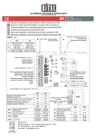
b. If specific interference sources cannot be avoided, they should at least
be kept at a distance from the regulator system.
c. Capacitive and inductive couplings can cause crosstalk between highvoltage lines and parallel low-voltage and sensor lines. This distorts
measured values and signals and can disrupt the entire regulatory
process. It is therefore recommended that all sensors and signal lines be
placed separately from the control and mains voltage lines.
d. If possible, a separate mains line should be provided to feed the regulator system. This helps reduce any interference penetrating the regulator
via the mains supply line. Voltage surges resulting from switching
substantial loads will also then be less of a problem.
e. In the case of contactors, solenoid valves and other inductive consumers, the induction voltage occurring during switching has to be reduced by appropriate protection methods. The choice of methods depends
on whether the consumer runs on DC or AC voltage.
U+
Regulator contact
Coil
Diode
U-
Regulator contact
AC
Coil
RCFilter
! DC voltage
In the case of d/c voltage systems, the induction voltage occurring
can, for example, be limited by using self-induction diodes,
varistors or suppresser diodes. The diagram on the left shows one
possibility using a self-induction diode.
! AC voltage
In the case of a/c voltage, interference suppression as described
above is not possible. Instead, an RC combination must be used.
An RC filter must be connected as directly as possible to the
inductance, in order to ensure a short line. In addition, the
component ratings of the RC combination must be geared to the
inductance. Too low ratings lead to excessive voltage, and too high
ratings cause significant losses in the interference suppresser
component. Another point to note here is that only capacitors which
meet VDE 0656 may be used. They must be suited to the mains
voltage and designed for very high switching voltages. The diagram
on the left shows inductance interference suppression using an RC
filter.
An RC filter should not be fitted directly to the regulator's switching
contact, as shown on the left, as an idle current will flow through the RC
combination even when the switching contact is open. This current may
be enough to mean that a downstream contactor is not de-energised
and a closed protective contact does not reopen.
MPR-M
26/08/08
Page 15