1
APPENDIX B
B.1.2
RS422 Interface
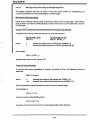
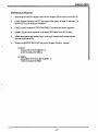
1.
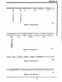
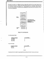
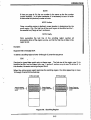
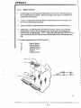
Install a snap-on mounting clip (P/N 283-339) into each of the 4 mounting holes on
the controller board (see figure). Make sure wings of each clip do not interfere with
components on the board.
2.
Orient U1 on the RS422 Interface Board (P/N 3515435) toward the left side of the
terminal controller board (see figure).
3.
Attach the RS422 Interface Board to the mounting clips on the controller board.
4.
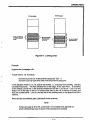
Aligning pin 1 of cable assembly (P/N 3515517) with pin 1 hole of U1 of Interface
Board and pin 1 hole of U40 of controller board, install cable assembly between
Interface and Controller boards. NOTE: If alternate cable assembly (P/N 636-215) is
used, use wire tie (P/N 302-335) to secure excess cable to lower-left side mounting
clip.
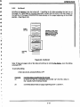
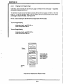
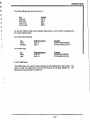
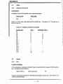
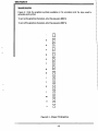
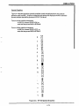
5. Pin signal assignments forthe RS422 port are:
15
17
19
25
7
1
Receive Data (+)
Receive Data (-)
Transmit Data (+)
Transmit Data (-)
Ground
Chassis Ground
B-4