Transcript
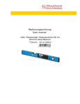
Operating Instructions
Resistance Thermometer WTH 160-250
Description
The resistance thermometer, type WTH 160-250 is designed to measure the temperature of high
voltage motors in end shields or windings and at other points respectively which are suitable for
measuring the temperature of this unit. It can be screwed in directly.
A sensor sleeve with a rotatable special-purpose screw M6 mounted on top houses a platinum thinfilm resistance element. A soldered connection connects this resistance element with the shielded
connecting lead. Both the resistance element and the connecting point to the connecting lead are
completely covered with potting compound. For the purpose of strain relief the connecting lead is
pressed in a transition sleeve connected with the sensor sleeve and embedded in a second transition
sleeve. Protection against buckling is achieved by an elastic potting compound filled into the second
transition sleeve after the fixing compound has been applied. A stainless steel spring is provided on
the second transition sleeve for further protection against kinking. Equipotential bonding of the
resistance thermometer WTH 160-250 is reached by screwing the sensor into the metal casing of the
motor. The resistance thermometer WTH 160-250 can be provided with one or two resistance
sensors. One sensor is suitable for thermometers with 2-, 3- or 4-wire connections and two sensors
for thermometers with 2- and 3-wire connections only.
The installation of the component has to be specified in the certificate of conformity of the electrical
equipment concerned. Damage to cables or insulation must be avoided during installation. The
connecting cable must be laid in a strain-relieved manner. The cable ends must be firmly connected to
suitable terminals. The sensor cable has to be connected to purpose-designed supply equipment for
passive resistance sensors only which is approved for the operation of the unit and in accordance with
the standard applicable for the resistance thermometer. The supply equipment must have one or two
connections which are adequate for the existing wiring. The electrical parameters must not be
exceeded.
The type of protection, encapsulation EEx m II, is provided by embedding the resistance element in
potting compound and installation of the resistance thermometer, type WTH 160-250. The materials
selected ensure a working temperature range of the resistance thermometer between –50°C and
180°C. The AC proof voltage of the thermometer is 1kV.
Parameters:
Operating voltage:
Sensor current, maximum:
Maximum power:
Maximum energy:
Self-heating:
Nominal resistance:
AC proof voltage:
Number of sensors:
Connection method:
Working temperature range:
Ui ≤ 30 V
2 mA
10 mW
10 Joule
≤ 1K (at maximum power in still air)
100 Ω/0°C, 500 Ω/0°C, 1000 Ω/0°C,
1.0 kV/50 Hz, 1 min.
1 or 2
1 sensor:
2-, 3- or 4-wire connection
2 sensors:
2- and 3-wire connection
-50°C ... 180°C
Marking:
Every resistance thermometer WTH 160-250 is provided with a label at the end of the connection
cable (see fig.).
----------------------------------------------------H. Heinz Messwiderstände GmbH 0341 ← (Manufacturing date=check number: YYWW)
WTH 160-250
II 2 G EEx m II
------------------------------------------------------This label gives all essential information on the resistance thermometer: type, manufacturing date,
explosion hazard.
Manufacturer:
H. Heinz Messwiderstände GmbH, Goethestrasse 16, D-98716 Elgersburg