1
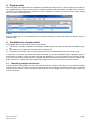
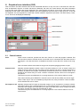
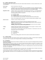
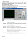
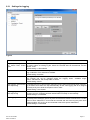
User guide to EasyPower Lite software Version: 3.01 Technical requirements for installation and operation: - PC with minimum 1.5GHz and minimum 512MB RAM Windows XP (32bit) / Windows Vista (32bit) / Windows 7 (32bit/64bit) Compatible to the device series: o PSI 9000 o PSI 8000 T o PSI 8000 DT o PSI 8000 2U o PSI 8000 3U o PSI 800 R o PS 8000T o PS 8000 DT o PS 8000 2U o PS 8000 3U - Compatible to these interfaces: o IF-U1 (USB) o IF-U2 (USB) o IF-R1 (RS232) o IF-R2 (RS232) o IF-E1B (both ports) Doc ID: EPL301EN Date: 27/09/2012 Page 1 1. Copyright This software is only compatible to power supply devices of the above listed series and to the listed interface cards and will be distributed with them. Any changes to the software and its documentation are prohibited. Exceptions require permission of the owner. Resale or rent are prohibited. Dissemination to third parties is permitted, if software and documentation remain unchanged. 2. Introduction EasyPower Lite is a tool to remotely control one or multiple power supplies with digital interface cards of type IFU1/U2 (USB), IF-E1B (USB/Ethernet) or IF-R1/R2 (RS232). Devices or interface cards unlike stated above are not supported. The program is based on the development environment LabView and requires a runtime engine which is automatically installed. Once the runtime engine is installed, other tools from us that are dedicated to control, for example, an electronic load, can be run and updated, too. 3. Preparation Before you run the software, you should connect at least one compatible device and, in case a USB port was used, make sure the driver is installed correctly. Correctly means, that it is strongly recommended to use the driver as supplied with the included CD. The driver installs two devices in the Windows device manager, one “USB Serial Converter” and one “USB Serial Port”. The latter one is listed in the “Ports (COM & LPT)” section. The terms are taken from Windows 7, terms of older Windows versions may vary here. When using USB or RS232 connection, the program only searches those COM ports. So in case the USB Serial Port for your device(s) is missing, EasyPower Lite can not find the device(s). When using a RS232 interface card, the connection speed (baud rate) in the device settings has to be set to: 57600 Note: usually, the driver has to be installed only once on the system. However, when adding a device with a USB port never connected before or plugging a known device into a different USB port of the PC, the devices will be assigned a different, new COM port. This is because the COM port is connected to the USB serial number of the USB interface card and to the USB port on the PC. 3.1 Installing EasyPower Lite The program is installed using a standard installer dialog. At the end of the installation, the installer will install a new font that is used to display the actual values in a 7 segment format in the main window of EasyPower Lite. The font installation requires a restart. Note: in case the font is not installed correctly, the program uses a replacement. This can be ignored, as the missing font does not disturb the normal program functionality. Note: in case the 7 segment font looks different to the example of the main window in figure 3 below, this is because the Window font smoothing feature ClearType is not activated. In order to make the font look normal, you can activate ClearType in the display settings of Windows. Otherwise, you could uninstall, i.e. erase the font (name: NI7SEG). Doc ID: EPL301EN Date: 27/09/2012 Page 2 4. Program start After every start, the program scans the hardware ports (default is COM ports only, can be changed in the options) for compatible devices. If only one unit is found, it instantly switches to the main display. If multiple units are found, it shows a list of the detected devices, waiting for the user’s selection. If no device was found, the list is empty, except for a note, that no device was found. Figure 1 Now you select one out of x detected devices for remote monitoring or control and submit the selection with the SUBMIT button. 5. Conditions for remote control The selected device can be in three different control states: 1). The device is currently controlled by the analogue interface (extern) and thus not remotely controllable by digital. 2). The device is in local state and thus locked from remote access. 3). The device is accessible. Then the PC will contact the device and automatically set it into remote control. In case item 3) is present, the device will accept commands and can be controlled remotely. Otherwise, only the actual values of voltage, current and power are read and displayed. In order to set the device into remote control, any external control or local state has to be cancelled manually at the device. Afterwards, it can be set to remote with button “Remote on”. Details about device states and handling can be found in the user manual of the device. 5.1 Controlling multiple units at once A single instance of the software can only control one unit at a time. However, the program can be started in multiple instances and in the scan result, in the list of detected devices, the remaining units are listed which are not already used by another instance. The main windows of the instances can be arranged on the screen to have the data of all units at one glance. Doc ID: EPL301EN Date: 27/09/2012 Page 3 6. Graphical user interface (GUI) After one device has been selected from the list of detected devices or if only one unit is connected, the main window, as depicted in figure 2 or similar, will show up. Basically, the menu, the control buttons, the status information area and the actual values are always displayed in the same position and layout. Only the set value area can vary, depending on the model. Some power supplies have power adjustment and for those an extra input box “P set” will be displayed. The same applies for models with internal resistance adjustment (PSI 8000 / PSI 9000 series). There, a box “R set” will be displayed additionally. Menu Control buttons Status information Actual values Set values Figure 2 6.1 Control buttons Scan Starts a scan for devices, just like from the menu „Device“ or when the program is started. This can be used to switch to another device if more than one is connected. Else the same device is used again. It can also be used to re-establish connection to the device if it seems to be hanging. Note: this button will be inaccessible as long as the sequencing/logging window is open. Remote on/off Manually switches between remote control of the device being on or off. In remote control, the status of the DC output and the set values can be changed, as well as running sequences is possible. By default, the program automatically switches the device into remote control, if not blocked by the device being in LOCAL condition. Automatic remote control can be changed in the options. This button may be inaccessible due to a running sequence or if the device status is LOCAL. Note: when switching from REMOTE to manual control of the device (FREE), the device might switch off the output. This is not initiated by EasyPower Lite, but by the device. There are differences between the various series. Set output on /off Manually switches the DC output of the power supply on or off, as well as it is used to acknowledge device alarms like overtemperature (OT) or overvoltage (OVP). If an alarm has occurred, the button text changes and it first has to be used to ACK the alarm, which usually shuts down the output, and then the output can be switched on again. This button may be inaccessible due to a running sequence or if the device status is not in remote control. Doc ID: EPL301EN Date: 27/09/2012 Page 4 6.2 Status information area The status information area normally shows five rows of device status information. In case of a device alarm, a sixth row is displayed. Device type Device model name in short form. User text A string/text of up to 15 characters which can be defined by the user to distinguish multiple identical. In order to set the user text, the device has to be connected via RS232 or USB and has to be in remote control. The user text can then be set in the Options dialog. Regulation mode Shows the device’s actual regulation mode while the DC output is on. It uses abbreviations like they are either displayed as text on the device display or by LEDs on the device front. Following regulation modes are supported: CV = Constant voltage CC = Constant current CP = Constant power (models with adjustable power only) CR = Constant resistance (only PSI 8000 or PSI 9000 series with unlocked option) Refer to the operating guides of the device for further information about regulation modes. Device access Shows the access condition of the device: free access = the device is free for access from outside, like remote control remote = the device is in remote control via digital interface and can not be controlled manually (except a few features) external = the device is in remote control via analog interface and can not be controlled manually (except a few features) or via EasyPower Lite Output Shows the DC output condition as the device reports it to the program. It means, it is also indicated during other remote control or monitoring. Error This information is usually hidden and only shown if an alarm, i.e. device error occurs. Following device errors can be indicated: OV = Overvoltage OT = Overtemperature PF = Power Fail Refer to the operating guides of the device for further information about alarms/errors. 6.3 Actual values The area with the actual values always shows the actual DC output values of voltage, current and power. Depending on the device series, the power value changes between unit Watt (W) and Kilowatt (kW). 6.4 Set values By default, three input boxes for the set values of voltage (U set), current (I set) and overvoltage protection threshold (OVP set) are available. With the series PSI 8000 and PSI 9000, which feature an optional internal resistance simulation, the operation mode can be switched from U/I/P to U/I/R and vice versa. EasyPower Lite will detect that condition and switch the power value input box (P sel) to resistance input (R sel). The power value input box is generally only available for models from 1000W total power, because with other models the power is not adjustable. Note: entering values is only possible if the device is in remote control. The entered values are limited to the device’s nominal values. This inhibits, for example, setting a voltage of 20V on a 16V model. Note: with series PSI 8000 or PSI 9000, the value „U>“ in the supervision settings is a lower limit for the OVP set value. Depending on the value of U> it can happen that the value entered for OVP is denied and a message will pop up. Doc ID: EPL301EN Date: 27/09/2012 Page 5 6.5 Menu The menu accesses some extra features which are not so often used. Some menu item can be deactivated depending on the situation. Entry Description Can be deactivated? Shortcut Device Information Scan Pops up a window with some device related information Scan the hardware ports for connected devices no yes Ctrl+I Ctrl+A Opens the sequencing / logging window Opens the sequence file, which has been selected in the options for the current device, in the assigned application yes Ctrl+L Opens the options windows yes Actions Sequencing/Logging View/edit sequence file yes View log file View application log file Graph Options Ctrl+O Arrange windows Tiled Cascaded Arranges the windows of the current instance of EasyPower Lite in tiled layout, if more than one window is opened (except options windows) Arranges the windows of the current instance of EasyPower Lite in cascaded layout, if more than one window is opened (except options windows) Help Help EN Help CN About Opens this English help file (PDF) Opens the Chinese help file (PDF) Exit Leaves the program Doc ID: EPL301EN Date: 27/09/2012 no no F1 Ctrl+F1 Page 6 7. The graph window The graph in the graph windows plots the chronological run of the actual and set values of voltage, current and power. It is just for visualization of the value that is read from the device. However, it can be used to select what values are recorded (Plots switches) and what’s the time range of the X axis. This window can be maximized to enlarge the plot area. Once the plot recording has stopped, the plot data can be exported directly from the graph to Excel or OpenOffice Calc or similar, via a CSV file. Note: this window can be maximized in order to enlarge the graph plot area. Note: the graph can record 2^32 values for each plot and uses max. 6x 4GB memory. Since most PCs don’t have 24GB free memory available, the graph history is thus limited to the PCs available memory. Once the graph history is full because all memory is used up, no data will be recorded anymore. Figure 3 1 Voltage scale Corresponds to the plots U set and U actual. Range is rigid by default, but can be switched to automatic mode with right-click of mouse. 2 Current scale Corresponds to the plots I set and I actual. Range is rigid by default, but can be switched to automatic mode with right-click of mouse. 3 Power scale Corresponds to the plots P set and P actual. Range is rigid by default, but can be switched to automatic mode with right-click of mouse. 4 Configure plots Configure the plots and scales color, line mode and refresh mode. 5 Graph tools These tools are used to zoom the graph area, even partial, or to move the recorded plots in order to view selected positions 6 Control buttons Start/Stop: this button starts or stops the graphical recording Reset: resets the graph to the beginning (time, X axis) and clears all plots. Close: resets the graph and closes the graph window Time range X axis: changes the time for the visible graph history (1s, 10s, 1min, 10min). This only affects how many values are displayed at once. 7 Plot switches These switch single plots on or off. By default, only actual values are recorded. 8 Scroll bar X Scrollbar for the history of recorded data. It automatically scrolls to the right if new data is recorded. Once the graph is stopped (manually or automatically), the history can be scrolled back to the beginning or any other position. Doc ID: EPL301EN Date: 27/09/2012 Page 7 8. Sequencing and logging A very important feature of the EasyPower Lite is the ability to process sequences and to log device data to a file. A sequence is a set of set values combined with a time x, defined in a text file of type CSV (values separated by semicolons, editable in Excel). The program will read and process the file line-by-line, send the set values for voltage, current and power to the device and then wait the given time x. After this, it processes the next line etc. The resistance set value, as with models with option “internal resistance” installed, can not be controlled by a sequence. The data logging basically works the same, but vice versa. Here the actual values (voltage, current, power), set values (ditto), date, time, device condition and errors are written into a text file of type CSV (values separated by semicolons). The interval can be defined from 500ms…99h59m59s, with a step width of 100ms. The total logging period and the number of logged entries is only limited by the PCs hard drive space. Due to Excel’s and similar tools’ limitation of 65536 rows per sheet, a single log file is filled up to about 65450 rows and then another log file will be generated and continued. The file name of the new file will be added with _001, _002 etc. Attention! The sequence processing differs to the one implemented in the function manager of the devices of the series PSI 9000 und PSI 8000. No ramps are created here. It means, the next value in the sequence is just sent to the device and set, resulting in leaps, but the device will not generate intermediate steps over the time x. Logging and sequencing are separately configured in the options. They both require a file of CSV type to be selected. For sequencing, the file has to have a certain format, which is given with the example sequence file that is installed with EasyPower Lite in the subfolder \data. The sequence is checked for compliance to the currently selected device and if there are errors, a window will pop up, listing the errors. Sequence files can be edited or created outside of EasyPower Lite with common tools like Excel or similar. 8.1 Sequencing In order to do sequencing, it first requires selecting a valid sequence file. The file is checked to be valid for the currently controlled power supply. If not valid, a window will pop up list the problems. It generally applies: all set values (U, I, P) in any of the sequence file rows must not exceed the nominal values of the device. Time values must not exceed the given time range (500ms...99h59m59s), minimum value (500ms) and step width (100ms). The subfolder \data of your EasyPower Lite installation contains an “example_sequence_file.csv”, which can be used for a start and which is selected by default after installation. There are buttons in the sequencing settings in options and in the sequencing/logging window and also in the menu to start the dedicated application for editing CSV files. This could even be a simple text editor. As soon as a valid sequence file has been selected in the options and if the device is in remote control, sequencing can be started in the sequencing/logging window. The table in the sequencing/logging window shows the currently processed row of the running sequence. The progress bar will indicate the progression of the steps within the sequence file in %, but not related to the total time the sequence will result in. If repetition has been activated in the options, a repetition counter will be displayed, counting the sequence file repetitions up to the desired number. Following also applies: At the start, sequencing switches the DC output on or off, depending on what is given in the first row of the sequence file. This can lead to high voltage steps. It is thus advised to define a clear start in the first row and switch the output off before the start. In case the DC output is on when the sequence is started and the given voltage in the first row is much lower than the actual output voltage while only a small load is attached, it might take longer for the output voltage to go down than the time which is given in the first row or even the 2nd row, too, so the first rows may not be executed correctly. Sequencing automatically stops at the end of a sequence or after the number of repetitions or if device errors like OV occur. Logging can be started and also stopped automatically, together with sequencing. There are settings for that in the options. Logging is only started automatically if a log file has been selected. The sequence file, which has been loaded for a certain device is stored in an INI file which is dedicated to the device. This INI and thus the sequence file are loaded the next time the device is detected and submitted, depending on the serial number. With this, there is no need to select a sequence every time you switch between devices. The INI files are stored in a subfolder \ini in the installation subfolder \data and can be deleted in case of problems. Doc ID: EPL301EN Date: 27/09/2012 Page 8 8.1.1 Sequencing settings Figure 4 Element Description Sequence file path The button to the right opens a dialog to select a sequence file. By default, an example sequence file from the installation is selected here. Default setting: example_sequence_file.csv Sequence file name Shows the sequence file name separately Sequencing with repetition Activates the repetition of the selected sequence file. Selectable range: 1...65500. Default setting: not activated Edit sequence file Doc ID: EPL301EN Date: 27/09/2012 Starts the software tool that is assigned to CSV files, in order to edit the sequence file outside of EasyPower Lite. Page 9 8.2 The sequence file format The sequence file itself has to be of Excel CSV format. Other than the definition of a CSV file, where values shall be comma separated, Excel and EasyPower Lite require the value to be separated by semicolons. This is because the comma is used in Europe to separate the decimal places in numbers. The installed example_sequence_file.csv, which can be found in the subfolder \data of your EasyPower Lite installation, can be used as a reference. In case a new sequence shall be created, it is recommended to copy an existing one and then edit it. Note: the example sequence file, as included and installed with the software, may contain values which are separated by commas as decimal separator. Depending on your local type of decimal separator, you may need to exchange the comma by a point, in order to make the sequence work correctly. The sequence file format is defined like this and with following requirements: Row 1 is used as a header and shall not be used for the first sequence step Columns G to J must be filled with values Column E is only effective for devices with adjustable power and can thus be left blank in sequence files for devices without adjustable power Text in columns A and B is not required, but is helpful for display in the sequencing/logging window and for the user to better understand the sequence file rows Any value in columns C to E must not exceed the related nominal values of the current device, or else the file is not accepted as valid. For example, if you create a file for 80V model and one row has a voltage value of 50V while all others are below 30V, then this file can not be used for a 32V power supply model. 8.3 Logging Recording data from the device, logging that is, can be done anytime. It means, it does not have to be in remote control. With this, you could for example control the device via analogue interface and via digital interface and EasyPower Lite, the actual values could be logged. Logging can be started and also stopped automatically if sequencing is used, too. This can be set up in the options. Generally, logging can only be started if a log file has been selected in the options. See below Following generally applies for logging: With a log file selected in the options, logging can be started and stopped manually at any time If logging is started automatically with sequencing, it can be stopped manually at any time In the options, you can either create a new log file or open an existing one. Existing files can be overwritten or data is attached, depending on the selected action. Use this option with care! If logging is started automatically with sequencing, the recorded data can not match. For example, if the first ten sequence file rows all have a time of 1s and the log interval is also set to 1s and the 1st row of the sequence files defines the set value of voltage as 10V, then the actual value of voltage, as recorded by the log file, can first appear one log row later. If log file action “Attach” has been selected in order to attach newly recorded data to old data, the new recorded is separated from the former record by a blank row and a header row with date/time of the new record. If a log file has reached the per file limit of 65450 rows, an overflow file with the appendix _001 is created, and _002 for the next file etc. The least created file will be saved as the selected file for logging if EasyPower Lite is closed. Doc ID: EPL301EN Date: 27/09/2012 Page 10 8.3.1 Settings for logging Figure 5 Element Description Log file path, Log file na- The button New opens a dialog to create a new log file (type CSV) while button Open can me, button New, button be used to select an existing log file, where the recorded data can be attached, if action Open „Attach“ is set. Default setting: no file selected Log file action Sets the action for the selected log file, whether new data overwrites old data when logging is started or if it is attached to old data. Default setting: Overwrite Log interval The log interval defines the time to elapse between two log file rows with recorded data. This interval can not be changed during the logging action. Available range: 500ms...99h59m59s, with a step width of 100ms. Default setting: 500ms Start logging automatically If activated and if a log file has been selected, logging starts automatically when sequencwith sequencing ing is started, but it does not stop automatically. In this case logging has to be stopped manually at any time while the sequence runs or after. Default setting: not activated Stop logging automatically If activated and if a log file has been selected, logging stops automatically when sequencwith sequencing ing stops, but only if logging has been started either manually or automatically. Default settings: not activated Stop logging on errors Doc ID: EPL301EN Date: 27/09/2012 Stops the data logging when a device error like OT or OV occurs, where the power supply usually does not supply power anymore and the actual values would be 0 for a certain period of time. Otherwise, if errors shall be recorded and also how long they have been present (subject: OT), then it is recommended to leave this option deactivated. Default settings: not activated Page 11 9. Application settings The menu item „Options“, as long as not blocked by the current operation of EasyPower Lite, opens the settings window. A part of the available settings, like „Communication“ is for the application and stored globally, some other settings are related to the devices you control with EasyPower Lite and stored separately for a device, like the logging and sequencing settings. Note: while no device is submitted for remote control in the current instance of EasyPower Lite, there are only three basic categories Communication, General and Language available. Other, device related settings can only be accessed after a compatible device has been detected and submitted. 9.1 Category: Communication The software can find and control compatible devices via COM ports (USB, RS232) or network (Ethernet). It requires selecting which of both is included in a scan for devices and for Ethernet, the IP range and port. Note: it is recommended to set the IP range as small as possible in order to save time when scanning for devices. Scanning an IP uses about 2-3s if no compatible device responds on that IP. Also, because only one port can be given here and in order to find all connected devices, the devices’ ports should be set to identical values. If this is not wanted, the port can be changed before the next scan or in another instance of EasyPower Lite, in order to find devices with different port settings. Note: port 80 must not be used, since it is reserved for the HTTP website. 9.2 Category: User text The user text is a string of up to 15 characters, which can be written into the device where it will be stored. The purpose of the user text is primarily to distinguish identical power supply models apart from their serial number. Setting this text in the options window is limited to the use of a COM port. But since the Ethernet interface IF-E1B has an additional USB port, this port can be used to write the user text. The user text is read from the device by EasyPower Lite and displayed in the main window in the status information area and in the list of detected devices. 9.3 Category: Logging Settings for the data recording feature „Logging“. For details see 8.3.1 Settings for logging. 9.4 Category: Sequencing Settings for the semi-automatic value table run feature „Sequencing“. For details see 8.1.1 Sequencing settings. 9.5 Category: General Here are application related settings: Element Description Application log file path The application can write a log file in CSV format which records actions and device errors with time and date. Default settings: EasyPower Lite_applog.csv Application log file name Shows the application log file name separately View application log file Opens the applog in an external tool which is assigned to CSV files. This feature can also be accessed from the menu. Save application log Activates the application logging feature. The applog only records application related events. Default setting: not activated Automatically activate remote control of the device If activated, the EasyPower Lite tries to set the submitted device automatically into remote control which is usually successful, unless the unit is in local mode. Default setting: activated Restore set values on start If activated, this will save the set values (U, I, P, R, OVP) of the currently controlled device to the device related INI file and restore them when that device is used by EasyPower Lite the next time. It then overwrites the last values of the device from manual use. Display refresh time (ms) Doc ID: EPL301EN Date: 27/09/2012 Display refresh interval in milliseconds. The actual values and set values, as well as device status are regularly read from the device and refreshed in the main window. In a situation where the actual would bounce too much because of a certain load behavior, this can be used to smooth the display by increasing the refresh time. Adjustable range: 300ms...1000ms in 100ms steps. Default value: 300ms Page 12 9.6 Category: Visualization / Graph Settings for the graphical value run feature „Graph“. Also see 7. The graph window. Element Description Time range X axis This selection determines the standard time range for the visual data recording in the Visualization / Graph window. It is connected to the selector with the same name in that window. The higher the value, the more data is displayed at once. Available setting: 1sec, 10sec, 1min, 10min Default value: 1sec Auto-open graph on start If activated, EasyPower Lite opens the Visualization / Graph window automatically on the application start, after a device has been detected and submitted. This also happens after a new search & submit. Default setting: not activated Auto-run / Auto-stop graph Starts and/or stops the visual data recording in the Visualization / Graph window autowith logging matically when feature Logging is started or stopped. Default setting: not activated Auto-run / Auto-stop graph Starts and/or stops the visual data recording in the Visualization / Graph window autowith sequencing matically when feature Sequencing is started or stopped. Default setting: not activated Note: if the setting „Start logging automatically with sequencing“ is already activated in the category „Logging“, this option does not need to be in order to start visual data recording 9.7 Category: Language Select your desired language for the application GUI here. Available are: English, German. Other languages can be added upon request once a new version of EasyPower Lite becomes available. Doc ID: EPL301EN Date: 27/09/2012 Page 13


![H8DA(M)JA [轉換].ai - Anly Electronics Co., Ltd.](http://vs1.manualzilla.com/store/data/005792054_1-e40506c7505a129d0c559401a2fa00b1-150x150.png)