1
Miniball Autofill System User Guide
Author: Nigel Warr
Date: 15th May 2008.
Figure 1: The GUI
1
Logging in
There are now two autofill computers. One is intended to be the backup of the other. The new one is
pcepuis36.cern.ch and the old one is pcepuis20.cern.ch when it is in CERN. Only one should be running at
any one time and it is only possible to connect one at a time to the hardware. They should have the same
configuration from the users’ point of view, though the hardware is different. The account and password are
the same as on the DAQ computer.
If the machine has just booted, it will not be in graphical mode, so you have to type the command
“startx” to switch to graphical mode.
2
Nomenclature
The manifolds have letters A, B, C and D. The outlets are specified by the letter of the manifold and the
number of the outlet on that manifold. e.g. A1, A2, C3 etc.
1
3
Using the Graphical User Interface
Start the GUI by clicking on the button marked “Autofill” on the console of the filling computer or use the
command af config from the command line.
The three main regions of the display show the last fill status (the same as with the show last fill command, described in section 4.2 below), the detector temperatures as measured by the PT100s (the same as
with show pt100 command, also described in section 4.1 below) and the log messages from the system log
file /var/log/messages (see section 4.3.
In the middle there are buttons for each outlet. Red buttons indicate that emergency fills triggered by
either the absolute value of the temperature or by temperature rises are disabled, whereas green buttons
indicate that emergency fills are enabled for that outlet. Click to toggle between these two states.
The buttons in the middle are used to plot a graph of the temperature vs. time, plot a graph of fill duration
vs. time, to configure the filling times, to force a manual fill, to display the valve and sensor status or to quit.
Clicking on “configure times” opens up a window with two colums. On the left is the list of hours at
which the fills should take place (e.g. 04,12,20) and on the right the list of outlets to fill at that time. It
takes the information from the active crontab and writes it back when you press return or click on “Save”.
The GUI doesn’t allow you to select the number of minutes past the hour that it fills at, and always fills at
the top of the hour. If you really need to change the minutes, you’ll have to enter the crontab manually (see
section 6). Clicking on “Status” pops up a window which displays the status of the valves and sensors.
Clicking on “Manual fill” pops up a window in which you can give the list of outlets to fill. e.g. a1 a2
c1. Give them separated by spaces.
Finally, in the top right corner there is a picture of a polar bear, which does nothing at all:)
4
Monitoring the filling system
You can find out what the current status is by issuing the commands show pt100 to see the temperatures
and show last fill to show the last fill status. This information is also sent to the af info e-mail list after each
fill. The system also generates plots which it stores in the /home/warr/www/ directory. (If we could run a
web server, it would be possible to view them over the Internet).
4.1
show pt100
This command gives a temperature for each outlet and the time that this temperature was recorded. The
time should be within the last five minutes or so. The output is like:
Outlet
A1
A3
A4
C1
C2
C3
4.2
Temp
92.0
99.4
97.0
97.8
98.0
96.1
K
K
K
K
K
K
Timestamp
Thu Jan 9
Thu Jan 9
Thu Jan 9
Thu Jan 9
Thu Jan 9
Thu Jan 9
09:10:01
09:10:01
09:10:02
09:10:03
09:10:03
09:10:03
2003
2003
2003
2003
2003
2003
show last fill
This command should give an output like:
Date
Thu
Wed
Thu
Thu
Thu
Thu
Thu
Time
Jan
Jan
Jan
Jan
Jan
Jan
Jan
09
08
09
09
09
09
09
04:00:01
10:00:01
04:00:01
04:00:01
04:00:01
04:00:01
04:00:01
Outlet
A1
A2
A3
A4
C1
C2
C3
Program
status
SUCCESS
SUCCESS
SUCCESS
SUCCESS
SUCCESS
SUCCESS
SUCCESS
Outlet
status
DONE
DONE
DONE
DONE
DONE
DONE
DONE
Fill
type
AUTOMATIC
AUTOMATIC
AUTOMATIC
AUTOMATIC
AUTOMATIC
AUTOMATIC
AUTOMATIC
2
Purge
time
110
92
110
110
78
78
78
Fill
time
252
254
251
237
196
186
180
In this example, all of the outlets were filled at 4 AM on the 9th except for A2 which was taken out of
the system (deliberately in this case).
The fill types can be MANUAL, AUTOMATIC or EMERGENCY depending whether the fill was issued
by a user from the command line, by the cron daemon automatically, or by the PT100 indicating a detector
was warm or warming up.
The purge times should be just over a minute unless the manifold was already cold, in which case it will
be shorter and the fill times should be under 5 minutes. A negative value indicates that the purge or fill
didn’t even start. This should be accompanied by an error message in the outlet status column.
The program status only indicates what happened to the program, not the fill. In other words, it indicates
“SUCCESS” if the program terminated cleanly, even if it was unable to fill correctly on all the outlets. Look
at the individual outlet status to see whether filling was successful. Possible values for the program status
are:
• INITIALISING - it crashed before it even got properly started.
• KILLED - it received a signal. This could be a control C issued from the keyboard, an explicit kill or
a serious program failure such as a segmentation violation.
• PURGING - it failed during the purge.
• FILLING - it failed during the fill.
• HARDWARE ERROR - it could not speak to the manifold properly.
• KEY ERROR - the key was in the manual position so it couldn’t do anything at all.
• PURGE TIMEOUT - the maximum purge time was reached without seeing any LN2 at the outlet.
Probably the LN2 vessel was empty.
• SUCCESS - the program terminated at the end of its fill cycle, whether or not the fill succeeded.
• OUTLET ERROR - one or more of the outlets failed to fill correctly, causing the program to terminate
prematurely.
Possible values for the outlet status are:
• DONE - all OK and everything is fine
• PURGE - it was purging the manifold when it failed
• WAIT LN2 - it was waiting for LN2 at the detector outlet when it failed.
• GOT LN2 - it got LN2 at the detector and failed when it tried to close the valve.
• WAIT DRY - it got LN2 at the detector outlet and closed the valve, but failed before the LN2 stopped
flowing.
• ABORT - the program was terminated due to an error condition.
• IGNORE - the program was not told to fill this outlet (this shouldn’t appear in a log entry).
• FAILED - it failed to fill that outlet.
All except DONE are error conditions and should not be ignored.
4.3
The system log /var/log/messages
The fill program writes messages to standard output when called from the command line and in all cases
writes messages to the system log file /var/log/messages
4.4
xv /home/warr/www/temps.png
This command plots the evolution of the temperatures over the previous week as a function of time graphically.
3
4.5
xv /home/warr/www/2days.png
This command plots the evolution of the temperatures over the previous 48 hours as a function of time
graphically.
4.6
xv /home/warr/www/durations.png
This command plots the filling duration as a function of time graphically. If the filling time rises, it could be
either that the threshold of the LN2 sensor needs adjusting or that the LN2 line is icing up. Look at it while
it is filling and if the LN2 detect light on the manifold control box doesn’t come on as soon as LN2 starts
flowing properly, the potentiometer needs adjusting (with a screwdriver). If that is fine, there is probably
ice in the line, so thaw it out and let the water out.
5
Monitoring the system from the web
The outputs of show pt100, show last fill and the temperature and fill duration plots are periodically copied
to http://www.ikp.uni-koeln.de/∼warr/pt100.html. You should check the timestamps on the fill and PT100
times to make sure that they are current, because if the network is down, this information is not updated.
6
Automatic filling
The automatic filling is performed using cron (see the cron(8) man page) and runs under the miniball
account. Log into that account and you can use the command “crontab -l” (see the crontab(1) man page)
to see the current configuration. This should give something like the following. The syntax is described in
the crontab(5) man page:
[email protected]
# Read the PT100 values every five minutes
0-59/5 * * * * /usr/bin/read_pt100
# Fill
00 04,10,16,22 * * * /usr/bin/fill --auto a1 a3 a4 c1 c2 c3 > /dev/null
The last line is the only one which you should ever change. Note that the mail address here is for cron
errors, not fill system errors, so don’t change it.
The first value in the last line (“00”) means that the fill takes place at zero minutes past the hour.
The second entry (04,10,16,22) indicates that fills occur at 4 AM, 10 AM, 4 PM and 10 PM. So if you
want to change the fill times, that is the place to do it.
The only other thing which you should change is the list of outlets (“a1 a3 a4 c1 c2 c3” in the example)
to be filled.
The “–auto” must be there and is used to let the fill program know that this is a scheduled automatic
fill rather than a manual one. Don’t change it.
The pipe to /dev/null should also not be changed. It is to stop the fill program sending messages back
to cron. The same messages are sent to the system logger and end up in /var/log/messages so you should
look there if you need them. In general they are only useful for debugging.
In order to change the crontab use the command “crontab -e”. This should start emacs on the crontab.
Just edit it as you desire, but be careful not to get the syntax wrong, and when you save and exit, it will be
installed.
7
Emergency filling
Emergency filling is completely independent of automatic filling. It is controlled by the PT100 readout. If
a PT100 readout indicates a detector is either warm (between 105 K and 200 K) or if the temperature rises
at more than 1 K per minute up to 130 K, an emergency fill will be triggered on the corresponding outlet,
regardless of whether it is configured or not in the crontab for the automatic fill.
4
So always make sure that the appropriate LN2 line is connected for any detector which has a PT100
connected to the readout.
In theory, if a PT100 is not connected, that detector should never receive an emergency fill. Unfortunately,
sometimes we seem to get glitches on the hardware which cause it go give false readings. For this reason,
we have a file which lists the detectors which are disabled for emergency fill purposes (they can still be filled
manually or automatically). To change the list of detectors for which emergency fills are disabled, modify the
file /home/miniball/autofill/emergency fill disabled.sh. It is a bash shell script which is sourced and should
look something like:
#! /bin/bash
#
#
#
#
This is the list of detectors which are disabled for the purposes
of emergency fills triggered by the PT100 readout. This has no
effect whatsoever on the fills invoked manually by the user, or
automatically from cron.
DISABLEDLIST="A4 B1 B2 B3 B4 C4 D1 D2 D3 D4"
In this example only detectors A1, A2, A3, C1, C2 and C3 can be filled by the emergency fill.
Note that you can change this file from the GUI af config by clicking on the red/green buttons. In that
case, red means emergency fills are disabled.
8
Manual filling
To issue a fill manually use the command fill followed by the list of outlets to fill. The outlets have names
like A1 (manifold A, outlet 1) etc.
For example:
fill a1 a2 a3 c1 c2 c3
9
Filling by hand
If the software doesn’t work at all, try turning the key on the manifold control box below the filling computer
to the manual position. Then you can use the switches to open and close the valves.
First purge the manifold by opening the inlet and the purge valve until you see liquid nitrogen at the
purge outlet.
Then close the purge valve and open the valves for the detectors you want to fill, leaving the inlet open.
When each detector is full, close its valve and when all are full, close the inlet valve and return the key
to the automatic position.
If even that doesn’t work, you can always use a funnel and pour it in.
10
Disabling all fills
The file emergency fill disabled.sh can be used to disable emergency fills, but there is also another file
all fill disabled.sh which has the same format, but disables all fills on that outlet, including automatic and
manual fills. This is intended only for use by automatic scripts which detect a PT100 temperature high
enough that it is not desirable to cool the detector back down again without first pumping on it. If you try
to fill an outlet disabled in all fill disabled.sh the fill program will write an error message to standard error
and ignore the request (though it will fill any other outlets requested which are not disabled).
11
E-mail lists
The autofill system uses four e-mail aliases which are defined in the files /home/miniball/alias af*.txt. They
are:
5
• af sms for sending SMS messages via an e-mail to SMS gateway.
• af emerg for sending emergency messages
• af warn for sending warning messages
• af info for sending the normal log files after each fill.
The format of this file is a comma-separated list of e-mail addresses. Note that the format is critical, as
if it is wrong, nobody gets any e-mail.
12
PT100 calibration
The file /home/miniball/autofill/pt100 cal.dat has the offset and gain for the calibration of each PT100.
Typically the offset is around 18 and the gain around 0.44, but it may be desirable to adjust the offsets for
individual PT100s to allow for slightly different calibrations.
Note that you can disable the PT100 readout for a channel by setting the gain to something like 9.44,
so that all values are out of range. This is useful for channels that do not have a physical connection, which
can give spurious values.
13
Troubleshooting
If a fill command hangs and nothing happens, check if there is another fill command running. If so, do a
“killall fill” and try again. If one fill program is still running for some reason, even if it is not doing anything,
it keeps the semaphore locked, so no other fill can start.
If you get a HARDWARE ERROR status, check all the connections to the manifolds and the manifold
controller. This error occurs when the computer tells the manifold controller to set the valves to a particular
state and when it asks them what state they are in, they are not in the desired state.
If LN2 flows out of a purge or detector outlet, but the program doesn’t react to that, check that the LN2
detect light on the manifold controller box is reacting to the LN2. If it isn’t you probably need to adjust the
threshold using the screw (near the light on the controller box). They seem to drift with time, so if you see
that fill times are getting longer and longer, check that it is detecting LN2 as soon as it is really flowing.
If you hear the click of the valve for a detector outlet open (it vibrates a little when it is open too) but
no LN2 is flowing into the detector, the line is probably blocked. This can either be a kink of the line or
ice in the line. In the former case, straighten the line and in the later, stop filling, take the line out of the
detector, thaw it out, let the water run out, put it back and try again.
If the valves don’t open and the LEDs on the manifold control box don’t change when the program runs,
check the connection between the computer and the manifold control box.
If the LEDs change from red to green, but the valves don’t open, check the connection from the manifold
control box to the manifolds.
If the system fills, but no e-mail is sent, check the syntax of the .mailrc file in the autofill home directory.
Comments are not allowed and the mail program is a bit picky about the syntax. If that is OK, try sending
mail from the system using the mail command by hand and see what happens.
If the temperature on a PT100 suddenly starts oscillating, I have no idea what that is, but it is a nuisance.
The only thing I can suggest is to add that outlet to the disabled list for emergency fills and keep a close
eye on it, because it won’t have emergency filling to fall back on.
If a PT100 value suddenly appears in the list for a channel which has no PT100 connected, I don’t know
what that is either. Just make sure that outlet is in the disabled list.
If computer controlled filling doesn’t work, try turning the key to manual and operating the switches.
If you get a PURGE TIMEOUT condition and no LN2 comes out of the purge outlet, check there is LN2
in the vessel and the pressure is between 1.5 and 2 bar. If there is LN2 and no pressure, check that you
6
don’t have a leak.
If you get an error message “ERROR: fill disabled on A1” (or another outlet) this means that this outlet
is disabled in the all fill disabled.sh file.
If you the LEDs on the manifold control boxes for the manifold are off (they should normally either be
red (closed) or green (open) but never off) check that the manifolds have power and that the cables are
connected. If they are OK, it might be one of the two 0.5 Amp fuses inside the manifold control box. Note
that there are three fuses for this box and only one is accessible from the back. The other two are inside.
If any LEDs are lit at all, the one at the back is OK. We have had ones inside the control box blow on a
couple of occasions.
14
Switching between systems
This section explains how to switch between the old (pcepsc22) and the new (pcepuis20) filling computers.
The autofill computer not only controls the autofill, but it also monitors the UPS and controls the high
voltage.
The UPS is connected via a serial cable, which should be plugged into the filling computer directly.
The HV is controlled by a private network, which plugs into the second ethernet controller of the filling
computer. Both pcepsc22 and pcepuis20 have second ethernet controllers (the primary one being connected
to the normal CERN network. The second controller of whichever computer is to control the HV should be
plugged into an ethernet hub or switch and the HV should be plugged into the same hub or switch. There
should be no uplink to the outside world - it is supposed to be a private network (it must be for CERN
computer rules and if the HV system appears on the CERN network, the CERN network people deliberately
crash it!)
Make sure that this switch or hub, the HV mainframe and whichever computer is being used as a filling
computer obtains its power from the UPS.
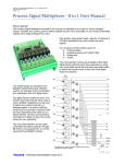
There are two PT100 boxes, one for the old ISA-based system and one for the new USB-based system.
They are quite different. The ISA system is a card inside pcepsc22 which has a connector that is connected
by a flat cable to the PT100 box. This card is an ADC and a few digital I/O lines. The I/O lines are used
to control a multiplexer inside the PT100 box, which connects the selected channel to the ADC. A current
source, also in the PT100 box, is used to send a constant current through the PT100 and the ADC measures
the voltage. From that we calculate the resistance and from there the temperature. The new PT100 system
consists of two USB-TEMP modules, which are mounted inside the new PT100 box. Each one is capable
of reading 8 PT100s independently. There is no connection between them inside the box and they have
separate USB connections to pcepuis20 (via a USB hub). However, as they give spurious readings when
only one channel is connected, and in any case, we need the D-sub connectors for compabibility, the box
provides an interface with a high resistance in parallel to the PT100. This has little impact on the measured
temperature, but insures that if the PT100 is unplugged, the neighbouring PT100 doesn’t give spurious
values.
For the PT100s, the only thing to do is unplug the D-sub connectors coming from the detectors from one
PT100 box and plug them into the other one.
The manifold control on the old ISA-based system consists of a 96-channel digital I/O card inside
pcepsc22, with two flat cables coming out, which plug directly into the manifold controllers for manifolds B
and D. The connection from B to A and from D to C is made by two short flat cables. The new system is the
USB equivalent of this card and is pin-to-pin compatible, so there are again two flat cables which connect
in exactly the same way to the manifolds B and D. Agian the connections from B to A and D to C is made
by the two short flat cables.
Do not run both computers at the same time as the one which is not connected to the UPS will complain
about this and they will interfere with each other when they try to update the website!
The procedure to switch from one system to the other is as follows:
• Shut down the computer, which was working as filling computer and switch it off.
• Unplug the serial cable which connects that computer to the UPS and plug it into the computer which
is to be the filling computer.
• Unplug the grey flat cables which connect manifolds B and D to the filling computer and plug in the
corresponding cables from the other computer in their place.
• Unplug the PT100 connectors (D-sub) which connect the detectors to the PT100 box and plug them
into the other PT100 box.
7
• Unplug the ethernet switch/hub from the second ethernet port of the computer which was being used
and plug into the second ethernet port of the other computer.
• Make sure that the computer which is to be used as filling computer is plugged into the UPS for its
power supply.
• Start this computer.
8