1
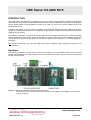
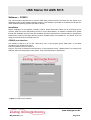
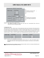
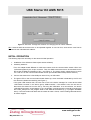
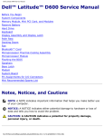
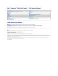
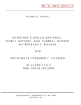
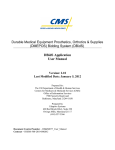
USB Starter Kit AMS 5915
User Guide
USB Starter Kit AMS 5915
Analog Microelectronics GmbH
An der Fahrt 13, D – 55124 Mainz
Phone:+49 (0)6131/91 0730-0
Fax: +49 (0)6131/91 073-30
Internet: www.analogmicro.de
E–Mail: [email protected]
May 2012 Rev. 1.0
USB Starter Kit AMS 5915
CONTENTS
INTRODUCTION
3
HARDWARE
3
SOFTWARE – CS5915
5
Installation
5
CS5915 user interface
5
INITIAL OPERATION
9
IMPORTANT NOTES
10
ADDITIONAL EQUIPMENT
10
ADDITIONAL DOCUMENTS
10
www.analogmicro.de
May 2012 Rev. 1.0
Page 2/10
USB Starter Kit AMS 5915
INTRODUCTION
The USB Starter Kit AMS 5915 is designed for quick and easy initial operation of AMS 5915 pressure
sensors with a standard PC with Windows operating system. Without additional components, the kit enables
current digital pressure and temperature values to be read out via the I2C sensor interface and to be
displayed on the PC.
In addition the starter kit can be used to program an individual I2C address into each AMS 5915 pressure
sensor. This customized I2C address is prerequisite for the operation of several AMS 5915 pressure sensors
together on one I2C bus.
The starter kit consists of two printed circuit boards and the relevant communication software package
CS5915 distributed on the starter kit CD. A Windows PC with an USB port and with operating system XP
SP3 or above is required for operation. The kit will be supplied by the USB port, an external supply isn’t
necessary.
NB: We recommend that you read the AMS 5915 sensor datasheet before putting the starter kit into
operation.
Hardware
The starter kit hardware consists of two printed circuit boards: the communication board CB-I2C and the
adapter board BB5915 with a ZIF-socket to connect one AMS 5915 sensor. Figure 1 shows the assembled
kit with mounted sensor.
Figure 1: USB Starter Kit AMS 5915 with connected sensor.
The kit consists of a communication board CB-I2C and an adapter board BB5915, connected by
a 34-pin connector.
www.analogmicro.de
May 2012 Rev. 1.0
Page 3/10
USB Starter Kit AMS 5915
The CB-I2C printing circuit board provides the hardware which enables a PC with USB-2.0 port to communicate with a pressure sensor with I2C interface. The BB5915 printed circuit board provides an easy way to
connect an AMS 5915 pressure sensor with the CB-I2C. Both printed circuit boards are connected by a 34
pin connector.
Using a standard USB cable the USB jack on the CB-I2C is connected to a free USB-port at the PC. The
PCs USB-port is used for communication and for power supply of the starter kit and the connected pressure
sensor; an additional supply isn’t required.
The connection between CB-I2C and BB5915 is realised by a 34 pin connector. A zero injection force (ZIF)
socket on the BB5915 allows easy mounting and exchanging of an AMS 5915 pressure sensor. Pin 1 of the
sensor is at the upper left edge of the ZIF-Socket (see Figure 1).
The sensor voltage can be chosen between 3.3V and 5V by jumper JP1 on CB-I2C (see Figure 1); for
standard products of the AMS 5915 series JP1 is connected to 3.3V. Further, for exchanging the mounted
AMS 5915 the sensor voltage supply can be turned off by removing JP1.
At the 4 pin plug connector on the BB5915 the sensor voltage supply VCC, GND and the I2C bus lines are
connected. This plug can be used for monitoring the sensor supply voltage and further for connecting and
testing sensors, which are already assembled.
For safety in cause of failure an electrical isolation between the sensor and the PC was realised on the CBIC. This avoids effectively an energy flow into the connected PC.
Table 1: Configuration of Jumper JP1 on CB-I2C
Sensor voltage
internal 3,3 V
internal 5 V
external supply
turned off
Jumper position JP1
central pin together with pin 3.3V
central pin together with pin 5V
removed
removed
Important:
1. If an AMS 5915 sensor is connected to the 4-pin plug connector on the BB5915, the sensor has to be
supplied by the starter kit to provide the full functionality of the starter kit software.
2. If it isn’t possible to supply the sensor by the starter kit, the jumper JP1 on the CB-I2C has to be
removed and the external power supply has to be connected to VCC-pin at the 4 pin plug connector on
the BB5915. In this case, a change of the I2C address isn’t possible.
3. If JP1 isn’t removed in case of an external sensor power supply at pin VCC, the starter kit can be
damaged!
www.analogmicro.de
May 2012 Rev. 1.0
Page 4/10
USB Starter Kit AMS 5915
Software – CS5915
The communication between the PC and the AMS 5915 pressure sensor (mounted onto the starter kit) is
realised by means of the software package CS5915. This software is provided on the starter kit CD and runs
under Windows operating systems (XP SP3 or above).
Installation
Before installation of the software package CS5915, please disconnect starter kit. By executing the file
CS5915_Setup.exe on the CD-ROM (must be run as an administrator), an installer is started which guides
through the installation process. After the installation process is finished, the necessary files for operating the
starter kit are copied to the target directory and the needed drivers are installed, too. The starter kit is now
ready to use and can be connected to the PC.
CS5915 user interface
The software CS5915 is run via the “AMS 5915” icon in the program group “AMS 5915” in the folder
programs in the windows start menu.
The user interface (menu) is shown in
Figure 2. The menu is divided in three submenus: “Communication Check”, “Measurement” und “Change I2C
Address” which are designed as index sheets. They will be described in detail below.
Figure 2: CS5915 user interface
www.analogmicro.de
May 2012 Rev. 1.0
Page 5/10
USB Starter Kit AMS 5915
Submenu “Communication Check”
The submenu “Communication Check” is to establish and to test the connection between the PC and the
AMS 5915 pressure sensor mounted onto the starter kit. By pushing the button “Search Starter Kit” (see
Figure 3 left) the link connection between the PC and the starter kit will be initiated. If it’s successful
(message: “Found Starter Kit”), the starter kit will be ready to use. Now, a connection to the AMS 5915
pressure sensor (mounted onto the starter kit) can be established. By pushing the button “Search Sensor
Address”, the software searches for an AMS 5915 sensor with a valid I2C address. A message follows,
whether a corresponding sensor was found or not. Figure 3 right shows an example of a sensor with the I2C
address 11hex.
Figure 3: Submenu “Communication Check”.
Left: A connection to the starter kit was established. Right: A sensor with the address 11 hex was
found.
After a successful initialisation of the connected starter kit, the remaining submenus will be enabled.
Note: If no starter kit was found after pushing the button “Search Starter Kit” please follow the tips given in
section Initial Operation paragraph 4. In case of the error message “No slave was found” is displayed
(after pushing the button “Search Sensor”) please check the following: the connection of the two
PCBs, the position of JP1, the position of the AMS 5915 in the ZIF socket and the locking of the ZIFsocket.
Submenu “Measurement”
The submenu “Measurement” is divided in a configuration and a measurement part (see Figure 4). In the
configuration part, the correct AMS 5915 sensor type (mounted onto or connected to the starter kit) has to be
chosen by a drop down menu. In the measurement part, the read out measurement values for pressure and
temperature are displayed in digital units and in calculated physical units.
www.analogmicro.de
May 2012 Rev. 1.0
Page 6/10
USB Starter Kit AMS 5915
Selection of Sensor Type
and Pressure Range
Measurement Configuration
and Display of Measurands
Figure 4: View of the submenu “Measurement”.
The submenu is divided in a configuration area (top) and a measurement area, where the
measured values are displayed (bottom).
Configuration area:
With the drop down menu “Sensor Type”, the exact AMS 5915 sensor type connected to the starter kit has to
be selected with its exact ordering code (e.g.: AMS 5915-0005-D) (see Figure 5 left). For the selected type
the sensor pressure range is shown below. In case of a custom specific version or a sensor which is not in
the menu, the sensor type “customised” has to be selected. In that case the specified minimal and maximal
pressure values pmin and pmax have to be filled into the adequate fields below (as shown in Figure 5 right).
Figure 5: Selection of the used AMS 5915 sensor type.
Left: A sensor type AMS 5915-0005-D with a measuring range of 0- 5 mbar was selected. Right: A
customised sensor with a manually adjusted pressure range from -200 mbar up to 400 mbar was
selected.
NB: If the wrong sensor type is selected, sensor measurement data cannot be accurately evaluated and the
displayed pressure value in physical units is wrong!
www.analogmicro.de
May 2012 Rev. 1.0
Page 7/10
USB Starter Kit AMS 5915
Measurement area:
The measurement area is shown in Figure 6. Before starting a measurement, the I2C address of the
connected sensor has to be filled in the field “Sensor I2C Address (hex)”. This field displays by default the
value detected during the last scan in submenu “Communication Check”.
Figure 6: View on area “Measurement”
With the buttons “Continuous Measurement” and “Single Shot” on the left side, a continuous or a single
measurement can be started. In case of a continuous measurement, the time interval between the discrete
measurements can be selected by the drop down menu “Loop Time” on the right side. The continuous
measurement can be stopped by pushing the button “Continuous Measurement” again.
In general 4 data bytes are read from the sensors output register and converted to decimal values in pairs:
the first and second data bytes generate the decimal pressure and the third and fourth the decimal
temperature value. The current readout pressure and temperature data are displayed as digital (decimal)
values and also as values in physical units. The latter are calculated with the formula described in the data
sheet of AMS 5915 sensor series. The physical pressure unit can be selected by a drop down menu at the
right side of the displayed pressure.
For a single measurement “Single Shot” the current measurement data available at the AMS 5915 output
register is one-time read and continuously displayed. In case of the continuous measurement the
measurement data is repeatedly read out and displayed. By pushing the button “Log Values” at the left lower
edge, the readout digital values can be saved in a file. At the first time values have to be written, a windows
dialog appears to assign the file name and the folder to save in. The file includes only the digital values.
Submenu “Change I2C Address”
In the submenu “Change I2C Address” (see Figure 7) an individual I2C address can be programmed into the
connected AMS 5915 pressure sensor. The box “Current I2C Address” displays by default the hex address
value detected during the last scan in submenu “Communication Check”, which is the current I2C address of
the connected sensor. The new I2C address (between 00hex and 7Fhex) has to be written in the box “New I2C
Address” as a hexadecimal value. By pushing the button “Change I2C Address”, the new I2C address will be
programmed to the AMS 5915 EEPROM. Subsequent, the new I2C address will be checked by changing to
submenu “Communication Check” and run a sensor search. The result will be displayed.
www.analogmicro.de
May 2012 Rev. 1.0
Page 8/10
USB Starter Kit AMS 5915
Figure 7: Submenu “Change I2C Address” for changing the I2C sensor address.
NB: If several AMS 5915 sensors are to be operated together on one I2C bus, each sensor must first be
allocated its own individual I2C address.
INITIAL OPERATION
The following steps are necessary for the starter kit initial operation:
1. Installation of the Software CS5915 (see section software)
2. Assembly starter kit
First, the adapter board BB5915 for AMS 5915 sensor and the communication board CB-I2C are
connected together by the 34 pin connector. Then, the AMS 5915 sensor has to be mounted into the
ZIF socket on BB5915 (orientation of pin 1: see Figure 1). The sensor supply voltage has to be set to
3.3 V with JP1 on the communication board CB-I2C (for standard AMS 5915 pressure sensors).
3. Connect the starter kit to a free USB port at the PC by an USB cable.
4. The green LED on the communication board flashes up, when the board is detected by the PC and
the drivers are loaded successfully (see Figure 1).
If the green LED remains dark, the user has to look in the device manager for a new device called
“USB Serial Converter” in the device group “USB-Controller”. If this doesn’t exist, the user has to
disconnect the starter kit from the PC by removing the USB-cable. At a reconnection, the device
“USB Serial Converter” should appear. If not, the problem could be solved by manually executing the
file Treiber_Setup.exe in the program folder of the AMS 5915 Software (e.g.: C:\program files\AMS
5915). If the led remains still dark and the starter kit wasn’t found, contact Analog Microelectronics
for further support.
www.analogmicro.de
May 2012 Rev. 1.0
Page 9/10
USB Starter Kit AMS 5915
IMPORTANT NOTES
1. For changing an AMS 5915 pressure sensor while the communication board is connected to the PC,
we recommend to remove the jumper JP1. It prevents sensor damage.
2. If the sensor is supplied externally, the jumper JP1 has to be removed and the external power supply
has to be connected to pin VCC at the 4 pin plug connector. However, in this operation mode a
change of the sensor I2C address is impossible.
3. The communication Board CB-I2C can be used for read out pressure sensors of the series AMS
5105 and AMS 5812, too. For starting up, only the corresponding adapter boards BB5105
respectively BB5812 and the according software CS5105 respectively CS5812 are necessary.
ADDITIONAL EQUIPMENT
•
USB-cable 2.0, FullSpeed A-St to B-St .
ADDITIONAL DOCUMENTS
•
Data Sheet of AMS 5915 Pressure Sensor Series
Analog Microelectronics GmbH reserves the right to amend any dimensions, technical data or other information contained herein without prior notification.
www.analogmicro.de
May 2012 Rev. 1.0
Page 10/10