1
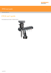
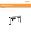
TP7 user's guide http://www.renishaw.com TP7 user's guide Documentation part number H-1000-5010-06-A Issued 11 2014 1 TP7 user's guide http://www.renishaw.com General information © 2003 2014 Renishaw plc. All rights reserved. This document may not be copied or reproduced in whole or in part, or transferred to any other media or language, by any means, without the prior written permission of Renishaw. The publication of material within this document does not imply freedom from the patent rights of Renishaw plc. Disclaimer RENISHAW HAS MADE CONSIDERABLE EFFORTS TO ENSURE THE CONTENT OF THIS DOCUMENT IS CORRECT AT THE DATE OF PUBLICATION BUT MAKES NO WARRANTIES OR REPRESENTATIONS REGARDING THE CONTENT. RENISHAW EXCLUDES LIABILITY, HOWSOEVER ARISING, FOR ANY INACCURACIES IN THIS DOCUMENT. Trademarks RENISHAW® and the probe emblem used in the RENISHAW logo are registered trademarks of Renishaw plc in the UK and other countries. apply innovation is a trademark of Renishaw plc. All brand names and product names used in this document are trade names, service marks, trademarks, or registered trademarks of their respective owners. Windows XP, Windows 2000, Vista and Windows 7 are registered trade names of the Microsoft Corporation. All trademarks and trade names are acknowledged. WEEE The use of this symbol on Renishaw products and/or accompanying documentation indicates that the product should not be mixed with the general household waste upon disposal. It is the responsibility of the end user to dispose of this product at a designated collection point for waste electrical and electronic equipment (WEEE) to enable reuse or recycling. Correct disposal of this product will help save valuable resources and prevent potential negative effects on the environment. For more information, please contact your local waste disposal service or Renishaw distributor. Warranty Renishaw plc warrants its equipment for a limited period (as set out in our Standard Terms and Conditions of Sale) provided that it is installed exactly as defined in associated Renishaw documentation. Prior consent must be obtained from Renishaw if non-Renishaw equipment (e.g. interfaces and/or cabling) is to be used or substituted. Failure to comply with this will invalidate the Renishaw warranty. Claims under warranty must be made from authorised service centres only, which may be advised by the supplier or distributor. Issued 11 2014 2 TP7 user's guide http://www.renishaw.com Care of equipment Renishaw probes and associated systems are precision tools used for obtaining precise measurements and must therefore be treated with care. Changes to Renishaw products Renishaw reserves the right to improve, change or modify its hardware or software without incurring any obligations to make changes to Renishaw equipment previously sold. Issued 11 2014 3 TP7 user's guide http://www.renishaw.com Introduction The TP7M and TP7M EP (enhanced performance) touch-trigger probes provide superior measuring performance over kinematic switching probes throughout a wide range of gauging speeds. True 6way sensing (±X, ±Y, ±Z) with any stylus offers greater flexibility of application. The extended operating life makes the TP7M and TP7M EP suitable for the most highly automated and demanding measuring tasks. For applications requiring the highest possible accuracy, the TP7M EP version is specified for the smallest form measurement error. The TP7M and TP7M EP are equipped with the Renishaw autojoint connector to enable repeatable, automatic probe changing when utilising the Renishaw autochange system. The probes may be mounted in the quill of the CMM, using a PH10M PLUS motorised probe head, to provide automatic articulation. Alternatively, the PH6M fixed probe head may be used. The TP7M and TP7M EP probes must be interfaced to the CMM controller using the dedicated PI 7-3 probe interface unit. The PI 7-3 automatically detects and interfaces with the Renishaw TP20, TP6 and other types of kinematic switching probe, so that the optimum probe type for the application can be easily used on the same machine. Issued 11 2014 4 TP7 user's guide http://www.renishaw.com Product description TP7M probe The stylus is coupled to a strain sensing structure that is protected against excessive stylus displacement by a 6-way kinematic overtravel mechanism. Silicon strain sensors, which detect the small gauging forces applied to the stylus tip, are connected directly to the PI 7-3 interface via the Renishaw autojoint connector, the probe head and associated wiring. The sensor signals are amplified and the resultant ‘probe signals' proportional to the changes of strain, are compared with reference voltages to determine the status of the probe. CAUTION: The TP7M is susceptible to damage if dropped. It must, therefore, be handled with care. Dimensions PI 7-3 interface The PI 7-3 is a dedicated signal conditioner for interfacing the TP7M and TP7M EP probes or kinematic switching probes (TP2, TP20 or TP6 / TP6A) to the CMM controller. The recognition of the probe type is automatic.The interface determines the probe status, which is either triggered or seated (armed), and transmits signals to the CMM controller. Status and control signals are passed between the PI 7-3 interface, other Renishaw equipment and the CMM controller via the product interconnection system (PICS) ports. During high-speed position moves (fast traverse), it is necessary to reduce probe sensitivity to prevent vibration causing unwanted triggers. The CMM controller automatically switches the PI 7-3 into a low sensitivity mode, such that the vibration triggers are prevented, but a trigger is still issued to stop CMM motion if an unexpected collision occurs. This mode is known as “probe damped mode” and is indicated by an LED on the front panel. Issued 11 2014 5 TP7 user's guide http://www.renishaw.com NOTE: The probe cannot take accurate points when damped mode is selected. The CMM manufacturer sets the configuration of the PI 7-3 and it should not be necessary for the user to make adjustments except to operate the reset button, as explained later in the handbook. Part number summary Part number Description A-1073-0121 TP7M probe kit A-1073-0261 TP7M EP probe kit A-1073-0122 TP7M probe and stylus kit A-1073-0123 TP7M probe and stylus kit (including PS1-16R) A-1073-0263 TP7M EP probe and stylus kit (including PS1-16R) A-5726-0100 PI 7-3 interface Issued 11 2014 6 TP7 user's guide http://www.renishaw.com Specification The following data is derived from test rig measurements and may not represent the performance achievable on a CMM. Please contact your CMM supplier for overall system accuracy information. TP7M: Sense directions 6way: ±X ±Y Z 3D accuracy (test to ISO 10360 Pt 2)* N/A Unidirectional repeatability (2σ μm) Trigger level 1: 0.25 μm (0.00001 in) Trigger level 2: 0.25 μm (0.00001 in) XY (2D) form measurement deviation Trigger level 1: ±0.25 μm (0.00001 in) Trigger level 2: ±0.5 μm (0.00002 in) XYZ (3D) form measurement deviation Trigger level 1: ±0.5 μm (0.00002 in) Trigger level 2: ±1 μm (0.00004 in) Trigger force (at stylus tip) XY plane: 0.02 N Z axis: 0.15 N Overtravel force XY plane: 0.78 N Z axis: 11.75 N Weight 85 g (3 oz) Maximum extension (on a PH10 series head) 200 mm (7.87 in) Maximum recommended stylus length (M4 styli range) 150 mm (5.9 in) steel 180 mm (7.08 in) GF Mounting method Multi-wired autojoint Suitable interface PI 7-3 Automatic probe changing Autochange rack Operating temperature range 10 °C 40 °C (50 °F 104 °F) Issued 11 2014 7 TP7 user's guide http://www.renishaw.com TP7M EP (enhanced performance): Sense directions 6way: ±X ±Y Z 3D accuracy (test to ISO 10360 Pt 2)* <0.6 μm (0.000024 in) Unidirectional repeatability (2σ μm) Trigger level 1: 0.25 μm (0.00001 in) Trigger level 2: 0.25 μm (0.00001 in) XY (2D) form measurement deviation Trigger level 1: ±0.25 μm (0.00001 in) Trigger level 2: ±0.5 μm (0.00002 in) XYZ (3D) form measurement deviation Trigger level 1: ±0.5 μm (0.00002 in) Trigger level 2: ±1 μm (0.00004 in) Trigger force (at stylus tip) XY plane: 0.02 N Z axis: 0.15 N Overtravel force XY plane: 0.78 N Z axis: 11.75 N Weight 85 g (3 oz) Maximum extension (on a PH10 series head) 200 mm (7.87 in) Maximum recommended stylus length (M4 styli range) 50 mm (5.9 in) steel 80 mm (7.08 in) GF Mounting method Multi-wired autojoint Suitable interface PI 7-3 Automatic probe changing Autochange rack Operating temperature range 10 °C 40 °C (50 °F 104 °F) The data above applies for test conditions as follows: Stylus length 50 mm (1.97 in) Stylus velocity 240 mm / min (1.57 ft / min) * Test performed on a CMM specification U3 = 0.48 μm + L / 1000 Issued 11 2014 8 TP7 user's guide http://www.renishaw.com 3D measuring performance To standard ASME B89.4.1 – 1997 for point to point measurement. Typically, the 3D measuring performance (spherical characteristic) is better than 2 μm. This means that no matter from which direction the probe triggers, the maximum error will be less than 2 μm when standard qualification techniques have been employed using styli up to 50 mm long. The 3D measuring performance of the probe considers the following sources of probe error: Unidirectional repeatability XYZ pretravel variation Stylus ball sphericity The table below only applies to TP7M with the additional styli: Stylus configuration Straight Performance parameters 100 mm long 150 mm long Offset 5 mm long, 50 mm offset 50 mm long, 50 mm offset Sensitivity setting - level 1 Sensitivity setting - level 2 Unidirectional repeatability 0.5 μm 0.5 μm 2D form measurement deviation ±1 μm ±2 μm 3D form measurement deviation ±1.5 μm ±3.5 μm 0.7 μm 0.7 μm 2D form measurement deviation ±1.5 μm ±2.5 μm 3D form measurement deviation ±2.5 μm ±6 μm 2D form measurement deviation ±0.4 μm ±0.8 μm 3D form measurement deviation ±0.5 μm ±1 μm 2D form measurement deviation ±0.7 μm ±1.3 μm 3D form measurement deviation ±1 μm ±1.8 μm Unidirectional repeatability Typical performance data for TP7M probe The following information provides examples of the expected measuring performance of the TP7M when using M2, M3 and M4 styli in accordance with the stylus selection guidelines given earlier in this document. In all cases, the ‘contour' lines show probe performance figures using straight or rightangled stylus configurations. For the configuration shown, where M2-M3-M4 adaptors and M2 styli are used, the expected measuring performance from the probing system would be within ± 1.5 μm. Issued 11 2014 9 TP7 user's guide http://www.renishaw.com TP7M using suitable M2, M3 and M4 adaptors and M2 styli TP7M using suitable M3 and M4 adaptors and M3 styl Issued 11 2014 10 TP7 user's guide http://www.renishaw.com TP7M using M4 styli Issued 11 2014 11 TP7 user's guide http://www.renishaw.com Installation procedure Mounting the probe on the probe head CAUTION: Great care must be taken not to drop the probe when installing. Whenever practical, follow the instructions given later in this section to assemble the stylus to the probe before installing the probe on the probe head. Locate the probe on the probe head, ensuring that the alignment dots on the head and probe are adjacent, and then lock the autojoint by clockwise rotation of the slotted actuator shaft using an S10 key (supplied). Issued 11 2014 12 TP7 user's guide http://www.renishaw.com Assembling a stylus to the probe Screw the stylus into the threaded mount on the probe until finger tight. Fit the stylus tool(s) (supplied) into the stylus cross-hole and tighten using finger pressure. The stylus tool is designed to bend if over-tightened, preventing damage to the probe. If the stylus has been assembled with the probe in-situ on the probe head, it may be necessary to reset the probe. Refer to the following section ‘Resetting the probe'. Issued 11 2014 13 TP7 user's guide http://www.renishaw.com Resetting the probe The probe will automatically reset to the armed state when the PI 7-3 is powered up or the TP7M is fitted to the probe head. It may sometimes be necessary to perform a manual reset, for example after fitting a new stylus. Press the RESET button on the front panel for 2 seconds to reset the probe to the armed (seated) state. Indicator Colour Function POWER ON Green Mains power in TYPE STD Green Kinematic probe selected TYPE TP7 Green TP7M probe selected PROBE SEATED Green ON - Probe armed (seated) OFF - Probe triggered or no probe connected PROBE DAMPED Yellow PDAMP asserted CAUTION: Pressing the reset button inhibits probe triggers. Prior to pressing the button the CMM must be stationary, in manual mode, with the stylus clear of the workpiece. NOTE: The action of unlocking and locking the PH10 PLUS motorised head will perform the same function as the RESET button. Issued 11 2014 14 TP7 user's guide http://www.renishaw.com Probe operation The probe has two normal operating states, armed or triggered. The probe should be in the armed state except for the moments when the stylus is deflected against the workpiece. Probe armed When the probe is armed (sometimes called ‘seated' or ‘reset'), the following PI 73 front panel indicators will be ON: POWER ON TYPE: TP7M when a TP7M is fitted STD when a TP2 is fitted PROBE: SEATED Additionally, the probe head LED will be ON. Probe triggered Normally, when the stylus touches the workpiece, the SEATED LED on the PI 7-3 front panel will turn OFF. Also, the probe head LED will turn OFF. The probe should be allowed to remain in the triggered state only for the minimum time necessary to reverse the CMM motion and back-off from the workpiece. Speed of operation The TP7M will work at touch speeds between 0.5 mm/s and 40 mm/s. NOTE: For accurate measurement, it is essential that the moves used to qualify the probe and subsequent measurement moves are carried out at the same speed (to within ±10%). Use of touch speeds greater than 40 mm/s will result in significantly reduced measuring performance. Use of touch speeds less than 0.5 mm/s (beware of glancing touches or joystick operations) will result in a possible corruption of the system's trigger and seated reference positions. Pretravel variation Pretravel is the distance the probe travels between the stylus touching the surface and a trigger signal being sent to the CMM. Pretravel is compensated by the CMM computer by probe qualification. However, due to the design of standard probes and the changes in force required to trigger from different directions, there is a small variation in this pretravel. This is called pretravel variation. On most CMMs using standard software and very long styli (i.e. up to 100 mm), pretravel variation can become a large factor in the probe's total margin of error. It is most evident in inspection routines requiring measurement of form (e.g. following contours or measuring roundness). Many standard gauging practices, such as measurement of distance between bore centres, are largely unaffected by probe pretravel variation errors. Issued 11 2014 15 TP7 user's guide http://www.renishaw.com Stylus selection To obtain the best performance, apply the following considerations when selecting and fitting a stylus: Use the shortest possible stylus length Minimise the mass of the stylus by using the types with ceramic or GF stems where possible (refer to the Renishaw stylus catalogue for further information) Work with the recommended stylus limits (see graph below in recommended stylus limits) Ensure that stylus balls, threads and mating faces are kept clean Tighten styli using only the tools provided Always qualify the styli at the gauging speed set for the part measurement program - if the speed is changed re-qualify the stylus tip Use the largest ball diameter to minimise surface finish effect on measurement Whenever possible, use only styli from the M4 range - it is possible to adapt to the M3 or M2 styli, but this will result in reduced measuring accuracy and the user is advised to establish the suitability for the application Recommended stylus limits The figure below shows the two parameters of a stylus configuration which, when plotted onto the graph used to determine stylus limits, determine whether or not the stylus is within the specified limits of operation. The stylus parameters shown below are the mass (M) and the length (L) from the stylus mounting to the centre of gravity of the stylus. Stylus limits Graph to determine stylus limits Issued 11 2014 16 TP7 user's guide http://www.renishaw.com Trigger level Under certain conditions, vibration may cause false ‘air' triggers during gauging and it may be necessary to reduce the probe sensitivity. False triggers may occur when large or heavy stylus arrangements are used, or when there is floor transmission from nearby machinery or vehicles: Trigger level 1 – the highest sensitivity mode, provides the best measuring accuracy Trigger level 2 – lower sensitivity to vibration, but with a small loss of measuring accuracy. The trigger level is selected by switch number 9 on the rear panel of the PI 7-3 interface: Level 1 – switch 9 to right Level 2 – switch 9 to left. NOTE: The sensitivity in probe damped mode is fixed and is not changed by the position of switch 9. The stylus tip(s) must be requalified after changing the trigger level setting. Probing force This is the force required at the stylus tip to trigger the probe. The TP7M system is designed to trigger at very low forces to minimise distortion of the stylus, workpiece or CMM structure during measurement. Issued 11 2014 17 TP7 user's guide http://www.renishaw.com Overtravel forces The ability to carry long or heavy stylus confi gurations requires the TP7M to have overtravel forces significantly higher than probing forces. Because these overtravel forces are experienced beyond the trigger point, but within the probe overtravel, measurement accuracy is not affected. For measurement of very delicate components, or use of small styli (Ø0.3 mm or Ø0.5 mm), the overtravel forces may be suffi cient to damage the surface or break the stylus. The forces experienced at the stylus tip can be reduced by either extending the stylus tip further away from the probe (as shown below), or minimising the probe overtravel within the touch cycle (as shown below). Extending the stylus tip from the probe TP7M force / deflection profiles Issued 11 2014 18 TP7 user's guide http://www.renishaw.com Fault finding The probe fails to trigger when the stylus touches the workpiece, but the probe operates normally when the stylus is deflected by hand: PI 7-3 indicators Possible causes Remedy ‘SEATED' LED ON The trigger speed is too low. Probe normally to the workpiece surface. Increase gauging speed. The stylus is too heavy. Refer to the section ‘Stylus selection' for recommendations. The probe will not arm or the probe does not stay armed after pressing the ‘RESET' button: PI 7-3 indicators Possible causes Remedy ‘STD' LED ON Probe sensor faulty. Remove probe and test by substitution. ‘SEATED' LED OFF Probe connections open circuit. Check wiring from probe to PI 7-3 interface. The probe will not arm or the probe does not stay armed after pressing the reset button. The head LED is OFF: PI 7-3 indicators Possible causes Remedy ‘TP7' LED ON Probe sensor faulty or damaged by collision. Remove probe and test by substitution. ‘SEATED' LED OFF False (‘air') triggers occur while the CMM is stationary: PI 7-3 indicators Possible causes Remedy ‘TP7' LED ON Probe sensor failure. Remove probe and test by substitution. ‘SEATED' LED operates normally Faulty connection in autojoint, probe head or Inspect autojoint pins, check continuity of wiring from probe to wiring. interface. Excessive vibration from external source. Excessive vibration from CMM. Eliminate source or isolate CMM. Check air supply. Maintain CMM. False (‘air') triggers occur at gauging speed: PI 7-3 indicators Possible causes Remedy ‘DAMPED' LED OFF Stylus is too large or heavy. Use stylus arrangements within recommendations. ‘SEATED' LED operates normally Excessive vibration from CMM. Check CMM air supply. Maintain CMM air bearing system. Issued 11 2014 19 TP7 user's guide http://www.renishaw.com False (‘air') triggers occur at fast traverse speed: PI 7-3 indicators Possible causes Remedy ‘DAMPED' LED OFF Stylus is too large or heavy. Use stylus arrangements within recommendations. ‘SEATED' LED operates normally Excessive vibration from CMM. Check CMM air supply. Maintain CMM air bearing system. Traverse speed is too fast. Reduce traverse speed. The probe does not rearm after taking a point: PI 7-3 indicators Possible causes ‘TP7' LED ON The reset speed is to slow or the stylus has slowly deflected while Ensure that the direction of gauging and back-off is moving off the work piece surface. normal to the workpiece surface. ‘SEATED' LED OFF Remedy Refer to the section ‘Resetting the probe'. There is an unexpected loss of accuracy: PI 7-3 indicators Possible causes Remedy ‘TP7' LED ON Stylus damaged or ball is dirty. Inspect and clean stylus ball or replace and requalify the stylus. ‘SEATED' LED operates Stylus is too large or heavy. normally Check that the stylus joints are tight. The probe head is damaged or the mounting of the head ‘DAMPED' LED is OFF to the CMM quill is faulty. Use stylus arrangements within recommendations. at touch point The autojoint connector is damaged or dirty. Inspect and clean the autojoint connector. Refer to ‘Maintenance' section. The gauging speed has changed. Requalify stylus tips. The trigger level has changed. Issued 11 2014 20 Renishaw plc New Mills, Wotton-under-Edge, Gloucestershire, GL12 8JR United Kingdom T +44 (0)1453 524524 F +44 (0)1453 524901 www.renishaw.com/cmmsupport For worldwide contact details, please visit our main website at www.renishaw.com/contact Issued 11 2014