1
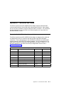
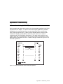
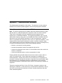
IBM 8-Port Asynchronous PCI Adapter Installation and User's Guide Note Before using this information and the product it supports, be sure to read the general information under "Product Warranties and Notices" included with your system unit. Fifth Edition (October 1998) The following paragraph does not apply to the United Kingdom or any country where such provisions are inconsistent with local law: THIS PUBLICATION IS PROVIDED “AS IS” WITHOUT WARRANTY OF ANY KIND, EITHER EXPRESS OR IMPLIED, INCLUDING, BUT NOT LIMITED TO, THE IMPLIED WARRANTIES OF MERCHANTABILITY OR FITNESS FOR A PARTICULAR PURPOSE. Some states do not allow disclaimer of express or implied warranties in certain transactions, therefore, this statement may not apply to you. This publication could include technical inaccuracies or typographical errors. Changes are periodically made to the information herein; these changes will be incorporated in new editions of the publication. The manufacturer may make improvements and/or changes in the product(s) and/or the program(s) described in this publication at any time, without notice. It is possible that this publication may contain reference to, or information about, products (machines and programs), programming, or services that are not announced in your country. Such references or information must not be construed to mean that these products, programming, or services will be announced in your country. Any reference to a specific licensed program in this publication is not intended to state or imply that you can use only that licensed program. You can use any functionally equivalent program instead. Requests for technical information about products should be made to your authorized reseller or marketing representative. International Business Machines Corporation 1995, 1998. All rights reserved. Note to U.S. Government Users -- Documentation related to restricted rights -- Use, duplication or disclosure is subject to restrictions set forth is GSA ADP Schedule Contract with IBM Corp. Contents Safety Information . . . . . . . . . . . . . . . . . . . . . . . . . . . . . . . . . . . . . . . . . . . . . . . . . . . . . . . . . . . . . . . . vii . . . . . . . . . . . . . . . . . . . . . . . . . . . . . . . . . . . . . ix ix ix ix Handling Static Sensitive Devices About This Book . ISO 9000 . . . . . . Related Publications Trademarks . . . . v . . . . . . . . . . . . . . . . . . . . . . . . . . . . . . . . . . . . . . . . . . . . . . . . . . . . . . . . . . . . . . . . . . . . . . . . . . . . . . . . . . . . . . . . . . . . . . . . . . . . . . . . . . . . . . Chapter 1. Overview Software Requirements . . . . . . . . . . . . . . . . . . . . . . . . . . . . . . . . . . . . . . . . . . . . . . . . . . . . . . . . . . . . . . . . . . . . Chapter 2. Preparing for Installation Inventory . . . . . . . . . . . . . . . . . Determining Cable Needs . . . . . . . . . . . . . . . . . . . . . . . . . . . . . . . . . . . . . . . . . . . . . . . . . . . . . . . . . . . . . . . . . . . . . . . . . . . . . . . . . Chapter 3. Installing Device Driver Software AIX Device Driver Software Installation . . . . Chapter 4. Installing Hardware . Installing the Adapter . . . . . . . . Verifying Adapter Available for Use Problem Determination . . . . . . . Check Cables and Adapter Seating Verify Software Installation . . . . . . . . . . . . . . . . . . . . . . . . . . . . . . . . . . . . . . . . . . . . . . . . . . . . . . . . . . . . . . . . . . . . . . . . . . . . . . . . . . . . . . . . . . . . . . . . . . . . . . . . . . . . . . . . . . . . . . . . . . . . . . . . . . . . . . . . . . . . . . . . . . . . . . . . . . . . . . . . . . . . . . . . . . . . . . . . . . . . . . . . . . . . . . . . . . . . . . . . . . . . . . Appendix A. Connectors and Cables . . . . . Connectors for the 8-Port Asynchronous Adapter Capacitance vs. Length of Run . . . . . . . . . . Connecting to a DTE Device . . . . . . . . . . . . Appendix B. Handshaking . . . . . . Software Handshaking (XON/XOFF) . Hardware Handshaking (Ready/Busy) . . . . . . . . . . . . . . . . . . . . . . . . . . . . . . . . . . . . . . . . . . . . . . . . . . . . . . . . . . . . . . . . . . . . . . . . . . . . . . . . . . . . . . . . . . . . . . . . . . . . . . . . . . . . . . . . . . . . . . . . . . . . . . . . . . . . . . . . . . . . . . . . . . . . . . . Appendix C. Communications Statements . . . . . . . . . . . . . . . . . . . Federal Communications Commission (FCC) Statement . . . . . . . . . . . . European Union (EU) Statement . . . . . . . . . . . . . . . . . . . . . . . . . . International Electrotechnical Commission (IEC) Statement . . . . . . . . . . . United Kingdom Telecommunications Safety Requirements . . . . . . . . . . . Avis de conformité aux normes du ministère des Communications du Canada 1-1 1-1 2-1 2-1 2-1 3-1 3-1 4-1 4-1 4-2 4-2 4-3 4-3 A-1 A-1 A-2 A-4 B-1 B-1 B-5 . C-1 C-1 C-2 C-2 C-2 C-4 Contents iii . . . . . . . . . . Canadian Department of Communications Compliance Statement VCCI Statement . . . . . . . . . . . . . . . . . . . . . . . . . . . . . Radio Protection for Germany . . . . . . . . . . . . . . . . . . . . . iv 8-Port Asynchronous PCI Adapter Installation and User's Guide . . . . . . . . . . . . . . . . . . . . . . . . . . . C-4 C-4 C-4 Safety Information DANGER An electrical outlet that is not correctly wired could place hazardous voltage on metal parts of the system or the devices that attach to the system. It is the responsibility of the customer to ensure that the outlet is correctly wired and grounded to prevent an electrical shock. Before installing or removing signal cables, ensure that the power cables for the system unit and all attached devices are unplugged. When adding or removing any additional devices to or from the system, ensure that the power cables for those devices are unplugged before the signal cables are connected. If possible, disconnect all power cables from the existing system before you add a device. Use one hand, when possible, to connect or disconnect signal cables to prevent a possible shock from touching two surfaces with different electrical potentials. During an electrical storm, do not connect cables for display stations, printers, telephones, or station protectors for communication lines. Safety Information v vi 8-Port Asynchronous PCI Adapter Installation and User's Guide Handling Static Sensitive Devices Attention: Static electricity can damage this device and your system unit. To avoid damage, keep this device in its static protective bag until you are ready to install it. To reduce the possibility of electrostatic discharge, follow the precautions listed below: Limit your movement. Movement can cause static electricity to build up around you. Handle the device carefully, holding it by its edges or its frame. Do not touch solder joints, pins, or exposed printed circuitry. Do not leave the device where others can handle and possibly damage the device. While the device is still in its anti-static package, touch it to an unpainted metal part of the system unit for at least two seconds. (This drains static electricity from the package and from your body.) Remove the device from its package and install it directly into your system unit without setting it down. If it is necessary to set the device down, place it on its static-protective package. (If your device is an adapter, place it component-side up.) Do not place the device on your system unit cover or on a metal table. Take additional care when handling devices during cold weather, as heating reduces indoor humidity and increases static electricity. Preface vii viii 8-Port Asynchronous PCI Adapter Installation and User's Guide About This Book Use this book with your system unit documentation to install the 8-Port Asynchronous PCI Adapter. Included are device driver install, configure, and verify instructions. ISO 9000 ISO 9000 registered quality systems were used in the development and manufacturing of this product. Related Publications This book refers to the following publications: Your system unit User's Guide AIX Version 3.2 and 4 Asynchronous Communications Guide, order number SC23-2488 Trademarks AIX is a registered trademark of International Business Machines Corporation. About This Book ix x 8-Port Asynchronous PCI Adapter Installation and User's Guide Chapter 1. Overview The 8-Port Asynchronous PCI Adapter (EIA-232E/RS-422A) is a multi-channel intelligent serial communications adapter. The adapter contains 128KB of 32-bit, dual-ported, high-speed RAM used to support program code and data buffering. The adapter supports a speed of up to 230Kbps (kilobits per second) for each asynchronous port and is run by a 32-bit 20 MHz IDT 3041 processor. The dual-ported RAM memory is accessible for read and write operations by both the adapter and the system unit. The system unit believes the dual-ported RAM is its own memory and accesses it by the same high-speed memory referencing commands it uses for its internal memory. Note: Additional information can be found in the Appendices. Refer to the following sections for cabling and handshaking information: Appendix A, “Connectors and Cables” on page A-1 Appendix B, “Handshaking” on page B-1 Software Requirements The 8-Port Asynchronous PCI Adapter is supported on AIX Versions 4.1.5 and 4.2.1 (with optional media containing device driver) or on later versions. Please insure this device is supported on your operating system prior to installation. Contact your support representative if you require assistance. Chapter 1. Overview 1-1 1-2 8-Port Asynchronous PCI Adapter Installation and User's Guide Chapter 2. Preparing for Installation This section helps you prepare to install your 8-Port Asynchronous PCI Adapter. The process includes: Taking an inventory of your installation materials Determining your cable needs Installing your device driver software Installing your adapter Note: If AIX is not installed on your system unit, install your adapter before you install the operating system (refer to Chapter 4, “Installing Hardware” on page 4-1). When you install AIX, your device driver software automatically installs. If AIX is operating on your system, install your device driver software prior to installing your adapter (refer to Chapter 3, “Installing Device Driver Software” on page 3-1). Inventory To install the 8-Port Asynchronous PCI Adapter, you need: The 8-Port Asynchronous PCI Adapter package – The 8-Port asynchronous adapter – A 25-pin D-shell wrap plug – The 8-Port asynchronous cable with fan-out box or connector assembly for the 8-Port Asynchronous PCI Adapter adapter The system unit User's Guide A flat-blade screwdriver (Optional) media containing device driver Determining Cable Needs Go to Appendix A, “Connectors and Cables” on page A-1. Chapter 2. Preparing for Installation 2-1 2-2 8-Port Asynchronous PCI Adapter Installation and User's Guide Chapter 3. Installing Device Driver Software This section explains how to install device driver software. AIX Device Driver Software Installation 1. Be sure you have read Chapter 2, “Preparing for Installation” on page 2-1. Determine if you should install your device driver software first or if you should install your adapter hardware first. If you should install your device driver software first, go to step 2 and continue with this section. If you should install your hardware first, go to Chapter 4, “Installing Hardware” on page 4-1. When you install AIX, your adapter device driver automatically installs. 2. Turn the system unit power on. 3. Log in as root. 4. Insert the media containing the device driver software (example: CD-ROM) into the appropriate media device. 5. Type the following smitty devinst and press Enter. 6. The Install Additional Device Software screen highlights the "INPUT device/directory for software" option. 7. Select or type your input device: Press F4 to display the input device list. Select the name of the device (example: CD-ROM) that you are using and press Enter. -- or - In the Entry Field, type the name of the input device you are using and press Enter. 8. The Install Additional Device Software window highlights the SOFTWARE to install option. 9. Press F4 to display the SOFTWARE to install window. Chapter 3. Installing Device Driver Software 3-1 10. Type the following to display the Find window: / 11. Type the following devices.pci.4f1111ðð and press Enter. (The system finds and highlights this device driver software.) 12. Press F7 to select the highlighted device driver software. Example: 4.2.1.ð devices.pci.4f1111ðð ALL 13. Press Enter. 14. The Install Additional Device Software screen displays. Entry data fields are automatically updated. Press Enter to accept the data. 15. The ARE YOU SURE window displays. Press Enter to accept the data. 16. The COMMAND STATUS screen appears. The term RUNNING is highlighted to indicate that the install and configure command is in progress. When RUNNING changes to OK, scroll down to the bottom of the page and locate the Installation Summary. After a successful installation, SUCCESS appears in the Result column of the summary at the bottom of the page. 17. Remove the installation media from the drive. 18. Press F10 to exit SMIT. 19. Go to adapter install procedure, Chapter 4, “Installing Hardware” on page 4-1. 3-2 8-Port Asynchronous PCI Adapter Installation and User's Guide Chapter 4. Installing Hardware This section provides the guidance necessary to install a PCI adapter. Before you begin, be sure you have read “Handling Static Sensitive Devices” on page vii. Attention: Do not remove the 8-Port Asynchronous PCI Adapter from its anti-static package at this time. Installing the Adapter 1. Be sure you have read Chapter 2, “Preparing for Installation” on page 2-1. Determine if you should install your adapter hardware first or if you should install your device driver software first. If you should install your adapter hardware first, go to Step 2 and continue with this section. If you should install your device driver software first, go to Chapter 3, “Installing Device Driver Software” on page 3-1 and return here to install your hardware. 2. Refer to the User's Guide that shipped with your system unit to perform the following and return to this document to continue. Shutdown your system unit. Install the PCI adapter in your system unit. Note: You remove a slot plate and screw to install the adapter. Store the plate, but use the screw to secure the endplate to the system unit chassis. The adapter endplate must be screwed to the system unit chassis to comply with Federal Communications Commission (FCC) rules, Part 15. 3. Connect the 8-Port Asynchronous cable with fan-out box to the adapter. 0 1 2 3 4 5 6 7 Figure 4-1. 8-Port Asynchronous cable with fan-out Box 4. Connect your external devices. 5. Turn on both your system unit and your display. Follow any instructions on the screen. Chapter 4. Installing Hardware 4-1 Verifying Adapter Available for Use To verify that your newly installed 8-Port Asynchronous PCI Adapter is available for use, follow the steps below: 1. If necessary, turn your system unit power on. 2. Log in as root. 3. At the prompt, type lsdev -Cc adapter | grep sa and press Enter. 4. A list of adapters displays. Verify that the 8-Port Asynchronous PCI Adapter is in Available mode. Example: sað sa1 sa2 Available ð1-Cð Standard I/O Serial Port 1 Available ð1-Dð Standard I/ð Serial Port 2 Available ð4-ð4 IBM 8-Port Async (PCI) Adapter Note: If the adapter is not available for use, go to “Problem Determination,” Step 2. Problem Determination Installation problems are often resolved using a few basic troubleshooting steps: 1. Verify that your adapter is Available for use. Go to “Verifying Adapter Available for Use” and return here. 2. Is your adapter on the list? NO Go to “Verify Software Installation” on page 4-3. YES Continue to Step 3. 3. Is your adapter in Available mode? 4-2 NO Go to “Check Cables and Adapter Seating” on page 4-3. YES Your adapter is recognized by the system and is functioning properly. (Even though the system recognizes your adapter, it is possible to have a configuration problem. If the problem persists, call your support representative.) 8-Port Asynchronous PCI Adapter Installation and User's Guide Check Cables and Adapter Seating 1. Turn off the system and repeat the Chapter 4, “Installing Hardware” on page 4-1 instructions to make sure the adapter is seated properly and the cable is attached properly. 2. If problems persist, call your support representative. Verify Software Installation If you tried “Verifying Adapter Available for Use” on page 4-2 and your adapter was not in the list, it may be because the device driver for your operating system has not yet been installed or did not install successfully. 1. Login as root. 2. Type: lslpp -l | grep devices.pci.4f1111ðð and press Enter. Example output follows: Fileset Level Status ----------------------------------------------------------------------devices.pci.4f1111ðð.asw 4.2.1.x COMMITTED PCI 8-Port Asynchronous devices.pci.4f1111ðð.com 4.2.1.x COMMITTED PCI 8-Port Asynchronous devices.pci.4f1111ðð.diag 4.2.1.x COMMITTED RISC PC PCI Async 8 Port devices.pci.4f1111ðð.rte 4.2.1.x COMMITTED PCI 8-Port Asynchronous devices.pci.4f1111ðð.rte 4.2.1.x COMMITTED PCI 8-Port Asynchronous Did example type information appear? NO Go to Step 5 on page 4-4. YES Continue to Step 3. 3. Are the filesets devices.pci.4f1111ðð.rte and devices.pci.4f1111ðð.asw installed at a level of 4.1.5.0 or higher? NO Go to Step 5 on page 4-4. YES Continue to Step 4. 4. For AIX version 4.1.5, type: lslpp -l devices.mca.ffe1.rte and verify this fileset level is at least 4.1.5.11. Chapter 4. Installing Hardware 4-3 For AIX version 4.2.1 or later, type: lslpp -l devices.common.IBM.cx and verify this fileset level is higher than 4.2.1.0. 5. If the filesets are not installed (or are not installed at the correct level), install the software using either instructions found in Chapter 3, “Installing Device Driver Software” on page 3-1 or in the instructions supplied with your installation media. 6. If your installation problems persist, call your support representative. 4-4 8-Port Asynchronous PCI Adapter Installation and User's Guide Appendix A. Connectors and Cables The 8-Port Asynchronous (EIA-232E/RS-422A) adapter supports both EIA-232E communications devices and the RS-422A communications devices. Each adapter port can be set by software to support either EIA-232E or RS-422A. The connectors on these adapters look the same but have different signals on the pins when the RS-422A interface is used. Connectors for the 8-Port Asynchronous Adapter The 8-Port Asynchronous (EIA-232E/RS-422A) adapter is shipped with a cable and an attached fan-out box or connector box that provides eight DB-25 standard connectors. The pin assignments for the male DB-25 connectors for the EIA-232E interface follow the EIA-232E DTE interface standard. The pin assignments for the male DB-25 connectors for the EIA-232E applications are shown in Table A-1. For RS-422A applications, the DB-25 connector pin assignments can be found in Table A-2 on page A-2. Table A-1. DB-25 Connectors for EIA-232E Applications Signal Description Use Pin Number GND Chassis Ground N/A Shell TxD Transmitted Data Output 2 RxD Received Data Input 3 RTS Request to Send Output 4 CTS Clear to Send Input 5 DSR Data Set Ready Input 6 SG Signal Ground Reference 7 DCD Data Carrier Detect Input 8 DTR Data Terminal Ready Output 20 RI Ring Indicator Input 22 Appendix A. Connectors and Cables A-1 Table A-2. DB-25 Connectors for RS-422A Applications Signal Description Use Pin Number GND Chassis Ground N/A Shell TxDb Transmitted Data b Output 2 RxDb Received Data b Input 3 TxDa Transmitted Data a Output 4 RxDa Received Data a Input 5 DSR Data Set Ready Input 6 SG Signal Ground Reference 7 DCD Data Carrier Detect Input 8 DTR Data Terminal Ready Output 20 Cables EIA-232E and RS-422A serial interface cables are shielded, low-capacitance cables that are designed for serial data transmission. Grounding A cable shield is grounded at both ends of the cable. A chassis ground is also available on the shell of the DB-25 connector. Environment Good shielding provides reasonable protection against noise (electromagnetic interference, or EMI); nevertheless, route cables away from noise sources if possible. Avoid laying cables in close proximity to transformers, generators, motors, fluorescent lights, or other electrical noise-producing equipment. Capacitance vs. Length of Run The total capacitance of a cable affects the integrity of transmitted data. As a general rule, the total capacitance of a cable (including the connectors) should not exceed 2500 pF for baud rates of up to 57,600 (1200 pF for 115K baud and 600 pF for 230K baud). Serial interface cable is usually rated in picofarads per foot (pF/ft). Therefore, if a cable has a capacitance of 50 pF/ft, and the connectors are 100 pF each, the maximum recommended cable length is 46 feet for baud rates of up to 57,600. If the cable is rated at 12.5 pF/ft, the maximum recommended cable length is 184 feet, and 5 pF/ft cable can be run up to 460 feet. A-2 8-Port Asynchronous PCI Adapter Installation and User's Guide Asynchronous Cable Connectors The asynchronous cables described below use the same connectors. The connector that attaches to the system has a female 25 pin D shell with sockets. The connector that attaches to the device has a male 25 pin D shell with pins. The figure below shows the ends of the 25 pin connectors. The system end is on the left and the device end is on the right. System End (Female) Device End (Male) POS 14 POS 14 POS 1 POS 1 Figure A-1. Asynchronous Cable Connectors Connecting to a Modem (EIA-232E Application) Figure A-2. Modem Cable Appendix A. Connectors and Cables A-3 Use a standard straight-through cable (see Figure A-2) to connect the modem to one of the DB-25 connectors on the connector box to utimately connect the 8-Port Asynchronous (EIA-232E/RS-422A) PCI adapter to a modem. Connecting to a DTE Device A DTE device can be a terminal, serial printer, or another system's serial port. To connect a DTE device (8-Port Asynchronous EIA-232E/RS-422A) PCI adapter to a DTE device, a null modem cable or adapter is required. A-4 8-Port Asynchronous PCI Adapter Installation and User's Guide Appendix B. Handshaking Software Handshaking (XON/XOFF) Serial terminals and printers often require only a three-signal connection to the 8-Port Asynchronous PCI Adapter. For device drivers that support XON/XOFF (software) handshaking, the required signal lines are transmitted data (TxD), received data (RxD), and signal ground (SG). Cables must be shielded and the shield must be connected to chassis ground (GND) at both ends of the cable run to remain in compliance with FCC certification requirements. The cable can be used as a null modem cable, that is, transmit data on one end of the cable is connected to receive data at the other end and vice versa. A cable of this type is shown in Figure B-1 for EIA-232E applications. Figure B-1. Simple Terminal/Printer Cable for EIA-232E Applications Appendix B. Handshaking B-1 Figure B-2. Simple Terminal/Printer Cable for RS-422A Applications The cable shown in Figure B-2 is a terminal/printer cable; RS-422A mode signal names are listed. The cable can be used as a null modem cable, that is, transmit data on one end of the cable is connected to receive data at the other end and vice versa. The male DB-25 end plugs directly into most serial terminals and printers without an adapter. The female DB-25 end plugs directly into one of the DB-25 connectors on the connector box assembly. B-2 8-Port Asynchronous PCI Adapter Installation and User's Guide Figure B-3. Terminal/Printer Cable for EIA-232E Applications The cable shown in Figure B-3 is a terminal/printer cable that can be used for various hardware and software protocols. The cable can be used as a null modem cable, that is, transmit data on one end of the cable is connected to receive data at the other end and vice versa. The male DB-25 end plugs directly into most serial terminals and printers without an adapter. The female DB-25 end plugs directly into one of the DB-25 connectors on the connector box assembly. Appendix B. Handshaking B-3 Figure B-4. Terminal/Printer Cable for RS-422A Applications The cable shown in Figure B-4 is a terminal/printer cable; the RS-422A mode signal names are listed. The cable can be used as a null modem cable, that is, transmit data on one end of the cable is connected to receive data at the other end and vice versa. The male DB-25 end plugs directly into most serial terminals and printers without an adapter. The female DB-25 end plugs directly into one of the DB-25 connectors on the connector box assembly. B-4 8-Port Asynchronous PCI Adapter Installation and User's Guide Hardware Handshaking (Ready/Busy) Figure B-5. Terminal/Printer Cable with DTR Handshaking EIA-232E Applications Most terminals and printers use data terminal ready (DTR) for ready/busy hardware handshaking. The cable shown in Figure B-5 supports this method and can be custom built. Instead of using DTR, some printers use a control signal called supervisory send data (SSD) on pin 11. For SSD, connect CTS on the female DB-25 side to pin 11 of the male DB-25 instead of connecting to pin 20. Other printer manufacturers may use different methods of flow control. Consult your printer's documentation for specific wiring requirements. Appendix B. Handshaking B-5 B-6 8-Port Asynchronous PCI Adapter Installation and User's Guide Appendix C. Communications Statements The following statement applies to this product. The statement for other products intended for use with this product appears in their accompanying documentation. Federal Communications Commission (FCC) Statement Note: The 8-Port Asynchronous PCI Adapter has been tested and found to comply with the limits for a Class B digital device, pursuant to Part 15 of the FCC Rules. These limits are designed to provide reasonable protection against harmful interference in a residential installation. This equipment generates, uses, and can radiate radio frequency energy and, if not installed and used in accordance with the instructions, may cause harmful interference to radio communications. However, there is no guarantee that interference will not occur in a particular installation. If this equipment does cause harmful interference to radio or television reception, which can be determined by turning the equipment off and on, the user is encouraged to try to correct the interference by one or more of the following measures: Reorient or relocate the receiving antenna. Increase the separation between the equipment and receiver. Connect the equipment into an outlet on a circuit different from that to which the receiver is connected. Consult an authorized dealer or service representative for help. Properly shielded and grounded cables and connectors must be used in order to meet FCC emission limits. Proper cables and connectors are available from authorized dealers. Neither the provider nor the manufacturer are responsible for any radio or television interference caused by using other than recommended cables and connectors or by unauthorized changes or modifications to this equipment. Unauthorized changes or modifications could void the user's authority to operate the equipment. This device complies with Part 15 of the FCC Rules. Operation is subject to the following two conditions: (1) this device may not cause harmful interference, and (2) this device must accept any interference received, including interference that may cause undesired operation. Appendix C. Communications Statements C-1 Responsible Party: International Business Machines Corporation New Orchard Road Armonk, New York 10504 Telephone: (919) 543-2193 Tested to Comply With FCC Standards FOR HOME OR OFFICE USE European Union (EU) Statement This product is in conformity with the protection requirements of EU Council Directive 89/336/EEC on the approximation of the laws of the Member States relating to electromagnetic compatibility. The manufacturer cannot accept responsibility for any failure to satisfy the protection requirements resulting from a non-recommended modification of the product, including the fitting of option cards supplied by third parties. Consult with your dealer or sales representative for details on your specific hardware. This product has been tested and found to comply with the limits for Class B Information Technology Equipment according to CISPR 22 / European Standard EN 55022. The limits for Class B equipment were derived for typical residential environments to provide reasonable protection against interference with licensed communication devices. International Electrotechnical Commission (IEC) Statement This product has been designed and built to comply with IEC Standard 950. United Kingdom Telecommunications Safety Requirements This equipment is manufactured to the International Safety Standard EN60950 and as such is approved in the UK under the General Approval Number NS/G/1234/J/100003 for indirect connection to the public telecommunication network. The network adapter interfaces housed within this equipment are approved separately, each one having its own independent approval number. These interface adapters, supplied by the manufacturer, do not use or contain excessive voltages. An excessive voltage is one which exceeds 70.7 V peak ac or 120 V dc. They interface with this equipment using Safe Extra Low Voltages only. In order to C-2 8-Port Asynchronous PCI Adapter Installation and User's Guide maintain the separate (independent) approval of the manufacturer's adapters, it is essential that other optional cards, not supplied by the manufacturer, do not use main voltages or any other excessive voltages. Seek advice from a competent engineer before installing other adapters not supplied by the manufacturer. Appendix C. Communications Statements C-3 Avis de conformité aux normes du ministère des Communications du Canada Cet appareil numérique de la classe B est conform à la norme NMB-003 du Canada. Canadian Department of Communications Compliance Statement This Class B digital apparatus complies with Canadian ICES-003. VCCI Statement The following is a summary of the VCCI Japanese statement in the box above. This product is a Class B Information Technology Equipment and conforms to the standards set by the Voluntary Control Council for Interference by Information Technology Equipment (VCCI). This product is aimed to be used in a domestic environment. When used near a radio or TV receiver, it may become the cause of radio interference. Read the instructions for correct handling. Radio Protection for Germany Dieses Gerät ist berechtigt in Übereinstimmung mit dem deutschen EMVG vom 9.Nov.92 das EG–Konformitätszeichen zu führen. Der Aussteller der Konformitätserklärung ist die IBM Germany. Dieses Gerät erfüllt die Bedingungen der EN 55022 Klasse B. C-4 8-Port Asynchronous PCI Adapter Installation and User's Guide IBM Part Number: 08L0510 Printed in the United States of America on recycled paper containing 10% recovered post-consumer fiber. ð8Lð51ð


![HiSoft Devpac 3 (text version) [1992] [Manual: PDF]](http://vs1.manualzilla.com/store/data/005668901_1-67cf8256fc448cd2edf58a11a6ec729e-150x150.png)