1
802.11ac Giga-Fast WiFi Router
AC1200R User’s Guide
FCC STATEMENT
This equipment has been tested and found to comply with the limits for a Class B digital device,
pursuant to part 15 of the FCC Rules. These limits are designed to provide reasonable protection
against harmful interference in a residential installation. This equipment generates, uses and can
radiate radio frequency energy and, if not installed and used in accordance with the instructions,
may cause harmful interference to radio communications. However, there is no guarantee that
interference will not occur in a particular installation. If this equipment does cause harmful
interference to radio or television reception, which can be determined by turning the equipment off
and on, the user is encouraged to try to correct the interference by one or more of the following
measures:
Reorient or relocate the receiving antenna.
Increase the separation between the equipment and receiver.
Connect the equipment into an outlet on a circuit different from that to which the receiver
is connected.
Consult the dealer or an experienced radio/ TV technician for help.
This device complies with part 15 of the FCC Rules. Operation is subject to the following two
conditions:
1) This device may not cause harmful interference.
2) This device must accept any interference received, including interference that may cause
undesired operation.
Any changes or modifications not expressly approved by the party responsible for compliance
could void the user’s authority to operate the equipment.
NOTE: THE MANUFACTURER IS NOT RESPONSIBLE FOR ANY RADIO OR TV
INTERFERENCE CAUSED BY UNAUTHORIZED MODIFICATIONS TO THIS EQUIPMENT.
SUCH MODIFICATIONS COULD VOID THE USER’S AUTHORITY TO OPERATE THE
EQUIPMENT.
FCC RF Radiation Exposure Statement
This equipment complies with FCC RF radiation exposure limits set forth for an uncontrolled
environment. This device and its antenna must not be co-located or operating in conjunction with
any other antenna or transmitter.
“To comply with FCC RF exposure compliance requirements, this grant is applicable to only
Mobile Configurations. The antennas used for this transmitter must be installed to provide a
separation distance of at least 20 cm from all persons and must not be co-located or operating in
conjunction with any other antenna or transmitter.”
Rev: 1.0.0
CE Mark Warning
This is a class B product. In a domestic environment, this product may cause radio interference, in
which case the user may be required to take adequate measures.
National restrictions
This device is intended for home and office use in all EU countries (and other countries following
the EU directive 1999/5/EC) without any limitation except for the countries mentioned below:
Country
Restriction
Bulgaria
None
Reason/remark
General authorization required for outdoor use and
public service
France
Outdoor use limited to 10
Military Radiolocation use. Refarming of the 2.4 GHz
mW e.i.r.p. within the band
band has been ongoing in recent years to allow current
2454-2483.5 MHz
relaxed regulation. Full implementation planned 2012
If used outside of own premises, general authorization is
Italy
None
required
General authorization required for network and service
Luxembourg
None
supply(not for spectrum)
This subsection does not apply for the geographical area
Norway
Implemented
within a radius of 20 km from the centre of Ny-Å lesund
Russian Federation
None
Note: Please don’t use the product outdoors in France.
Only for indoor applications
CONTENTS
Package Contents .................................................................................................................................1
Chapter 1. Introduction .......................................................................................................................2
1.1
Overview .............................................................................................................................2
1.2
Main Features .....................................................................................................................3
1.3
Panel Layout .......................................................................................................................4
1.3.1
The Front Panel ......................................................................................................4
1.3.2
The Rear Panel ......................................................................................................5
Chapter 2. Connecting the Router .....................................................................................................6
2.1
System Requirements .........................................................................................................6
2.2
Installation Environment Requirements ..............................................................................6
2.3
Connecting the Router ........................................................................................................6
Chapter 3. Quick Installation Guide ...................................................................................................8
3.1
TCP/IP Configuration ..........................................................................................................8
3.2
Quick Installation Guide ....................................................................................................10
Chapter 4. Configuring the Router ..................................................................................................17
4.1
Login .................................................................................................................................17
4.2
Status ................................................................................................................................17
4.3
Quick Setup.......................................................................................................................18
4.4
WPS ..................................................................................................................................18
4.5
TCP/IP Settings .................................................................................................................20
4.6
4.5.1
LAN .......................................................................................................................20
4.5.2
WAN Interface ......................................................................................................21
Wireless ............................................................................................................................29
4.6.1
Basic Settings .......................................................................................................29
4.6.2
Advanced Settings ................................................................................................31
4.6.3
Security .................................................................................................................33
4.6.4
Access Control......................................................................................................37
4.6.5
WDS Settings .......................................................................................................37
4.6.6
Site Survey ...........................................................................................................39
4.6.7
WPS......................................................................................................................40
-I-
4.6.8
4.7
Schedule ...............................................................................................................41
Firewall ..............................................................................................................................42
4.7.1
Port Filtering .........................................................................................................42
4.7.2
IP Filtering .............................................................................................................43
4.7.3
MAC Filtering ........................................................................................................43
4.7.4
Port Forwarding ....................................................................................................44
4.7.5
URL Filtering .........................................................................................................45
4.7.6
DMZ ......................................................................................................................45
4.7.7
VLAN ....................................................................................................................46
4.8
QoS ...................................................................................................................................47
4.9
Route Setup ......................................................................................................................47
4.10 Management .....................................................................................................................49
4.10.1 Status ....................................................................................................................49
4.10.2 Statistics ...............................................................................................................49
4.10.3 DDNS ....................................................................................................................50
4.10.4 Time Zone Setting ................................................................................................51
4.10.5 Denial-of-Service ..................................................................................................52
4.10.6 Log ........................................................................................................................53
4.10.7 Upgrade Firmware ................................................................................................54
4.10.8 Save/Reload Setting .............................................................................................55
4.10.9 Password ..............................................................................................................56
Appendix A: FAQ .................................................................................................................................57
Appendix B: Configuring the PC .......................................................................................................58
Appendix C: Glossary .........................................................................................................................61
- II -
AC1200R User’s Guide
Package Contents
The following items should be found in your package:
AC1200R
Power Adapter
Quick Installation Guide
Note:
Make sure that the package contains the above items. If any of the listed items are damaged or
missing, please contact your distributor.
-1-
AC1200R User’s Guide
Chapter 1. Introduction
Thank you for choosing the AC1200R.
1.1 Overview
The AC1200R equipped with gigabit LAN/WAN interfaces, plus Firewall, NAT-Router and Wireless AP
functionalities. The AC1200R delivers exceptional range and speed, which can fully meet the need
of Small Office/Home Office (SOHO) networks and users that demand higher networking
performance.
Incredible Speed
ccessontroInstallation
The AC1200R provides up to 300M wireless connection with 2.4GHz 802.11n wireless standards, and
867Mbps with 5GHz 802.11ac standards. The speed makes it ideal for handling multiple data streams
at the same time ensuring your network stability. It is compatible with all major wireless standards on
the market.
t
Multiple
Security Protections
The multiple protection measures include SSID broadcast control and wireless LAN 64/128-bit
WEP encryption, Wi-Fi protected Access (WPA2- PSK, WPA- PSK), as well as advanced Firewall
protections. The AC1200R provides complete data privacy.
Flexible Access Control
AccessontroInstallation
AC1200R provides flexible access control for parents and network administrators to establish
restricted access policies for children or staff members. It also supports port forwarding and DMZ host.
The network administrators can manage and monitor the network in real time with the remote
management function.
Simple Installation
Since the Router is compatible with virtually all the major operating systems, it is easy to manage
and operate. The Setup Wizard is supported and comprehensive step by step instructions are its
web configurator. Before installing the Router, please look through the user guide to know all the
Router’s functions.
-2-
AC1200R User’s Guide
1.2 Main Features
IEEE 802.11ac wireless technology to provide a wireless data rate of up to 1200Mbps.
One 10/100/1000M Auto-Negotiation RJ45 WAN port, four 10/100/1000M Auto-Negotiation
RJ45 LAN ports, supporting Auto MDI/MDIX.
Provides WPA/WPA2, WPA-PSK/WPA2-PSK authentication, TKIP/AES encryption security.
Shares data and Internet access for users, supporting Dynamic IP/Static IP/PPPoE Internet
access.
Supports Virtual Server, Special Application and DMZ host.
Supports UPnP, Dynamic DNS,.
Provides Automatic-connection and Scheduled Connection to the Internet on specified times.
Connects Internet on demand and disconnects from the Internet when idle for PPPoE.
Built-in NAT and DHCP server supporting static IP address distribution.
Supports Stateful Packet Inspection.
Supports VPN Pass-through.
Supports Parental Control and Access Control.
Provides 64/128-bit WEP encryption security and wireless LAN ACL (Access Control List).
Supports Flow Statistics.
Supports firmware upgrade and Web management.
-3-
AC1200R User’s Guide
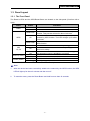
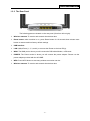
1.3 Panel Layout
1.3.1 The Front Panel
The Router’s LEDs and the WPS/Reset Button are located on the side panel (View from left to
right).
Name
PWR
Status
Off
On
Indication
Slow Flash
WPS
On
Quick Flash
Off
LAN
1,2,3,4
WLAN (2.4GHz)
WLAN (5GHz)
On
Flashing
Off
Flashing
Off
Flashing
Power is off.
Power is on.
A wireless device is connected to the network by WPS
function. This process will last for about 2 minutes.
A wireless device has been successfully added to the
network by WPS function. The LED will light up for about
2 minutes.
A wireless device failed to be added to the network by
WPS function.
There is no device linked to the corresponding port.
There is a device linked to the corresponding port but
there is no activity.
There is an active device linked to the corresponding port.
The Wireless function is disabled or not active
The Wireless active
The Wireless function is disabled or not active
The Wireless active
Table 1-1 The LEDs Description
Note:
1.
After the device has been successfully added to the network by the WPS function, the WPS
LED will light up for about 2 minutes and then turn off.
2.
To reset the router, press the Reset Button and hold for more than 10 seconds.
-4-
AC1200R User’s Guide
1.3.2 The Rear Panel
The following parts are located on the rear panel (View from left to right).
Wireless antenna: To receive and transmit the wireless data.
Reset button: when machine is on, press Reset button for 10 seconds then release reset
button to restore machine factory default settings.
USB interface:
LAN 1,2,3,4: Ports (1, 2, 3, and 4) to connect the Router to the local PC(s).
WAN: The WAN port is where you will connect the DSL/cable Modem, or Ethernet.
POWER: The Power socket is where you will connect the power adapter. Please use the
power adapter provided with the AC1200R.
WPS: Press WPS button to start easy wireless connection service..
Wireless antenna: To receive and transmit the wireless data.
-5-
AC1200R User’s Guide
Chapter 2. Connecting the Router
2.1 System Requirements
Broadband Internet Access Service (DSL/Cable/Ethernet)
One DSL/Cable Modem that has an RJ45 connector (which is not necessary if the Router is
connected directly to the Ethernet.)
PCs with a working Ethernet Adapter and an Ethernet cable with RJ45 connectors
TCP/IP protocol on each PC
Web browser, such as Microsoft Internet Explorer, Mozilla Firefox or Apple Safari
2.2 Installation Environment Requirements
Place the Router in a well-ventilated place away from any heater or heating vent
Avoid direct irradiation of any strong light (such as sunlight)
Keep at least 2 inches (5 cm) of clear space around the Router
Operating Temperature: 00℃~50℃
Operating Humidity: 10%~90%RH, Non-condensing
2.3 Connecting the Router
Before installing the Router, make sure your PC is connected to the Internet through the
broadband service successfully. If there is any problem, please contact your ISP. Install the Router
according to the following steps. Don't forget to pull out the power plug and keep your hands dry.
1.
Turn the power off for your PC, Cable/DSL Modem, and the Router.
2.
Locate an optimum location for the Router. The best place is usually at the center of your
wireless network environment.
3.
Adjust the direction of the antenna. Normally, upright is a good direction.
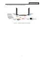
4.
Connect the PC(s) and each Switch/Hub in your LAN to the LAN Ports on the Router, shown
in Figure 2-1. (If you have the wireless NIC and want to use the wireless function, you can
skip this step.)
5.
Connect the DSL/Cable Modem to the WAN port on the Router, shown in Figure 2-1.
6.
Connect the power adapter to the power socket on the Router, and the other end into an
electrical outlet. Press the power switch, and then the router will start to work.
-6-
AC1200R User’s Guide
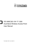
7.
Turn the power on for your PC and Cable/DSL Modem.
Figure 2-1
Hardware Installation of the AC1200R
-7-
AC1200R User’s Guide
Chapter 3. Quick Installation Guide
This chapter will show you how to configure the basic functions of your AC1200R using Quick
Setup Wizard within minutes.
3.1 TCP/IP Configuration
The default IP address for AC1200R is 192.168.26.1. And the default Subnet Mask is
255.255.255.0. These values can be changed to your preference.
Connect the local PC to the LAN ports of the AC1200R. You can configure the IP address for your
PC with the following options.
Configure the IP address manually
1)
Set up the TCP/IP Protocol for your PC. If you need instructions as to how to do this,
please refer to Appendix B: Configuring the PC.
2)
Configure the network parameters. The IP address is 192.168.2.xxx ("xxx" represents
any number from 2 to 254), Subnet Mask is 255.255.255.0, and Gateway is 192.168.26.1
(The Router's default IP address).
Obtain an IP address automatically
1)
Set up the TCP/IP Protocol in "Obtain an IP address automatically" mode on your PC.
If you need instructions as to how to do this, please refer to Appendix B: Configuring the
PC.
2)
The built-in DHCP server will assign an IP address for the PC.
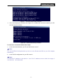
Now, you can run the Ping command in the command prompt to verify the network connection
between your PC and the Router. The following example is in Windows XP OS.
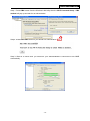
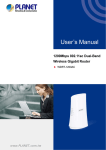
Open a command prompt, and type ping 192.168.26.1, and then press Enter.
If the result displayed is similar to the Figure 3-1, it means the connection between your PC
and the Router has been established well.
-8-
AC1200R User’s Guide
Figure 3-1
Success result of Ping command
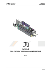
If the result displayed is similar to the Figure 3-2, it means the connection between your PC
and the Router has failed.
Figure 3-2
Failure result of Ping command
To check the connection follows these steps:
1.
Is the connection between your PC and the Router correct?
Note:
The 1/2/3/4 LEDs of LAN ports which you link to on the Router and LEDs on your PC's adapter
should be lit.
2.
Is the TCP/IP configuration for your PC correct?
Note:
The Router's IP address is 192.168.26.1. Your PC's IP address must be within the range of
192.168.26.2 ~ 192.168.26.254.
-9-
AC1200R User’s Guide
3.2 Quick Installation Guide
With a Web-based utility, it is easy to configure and manage AC1200R. The Web-based utility can
be used on any Windows, Macintosh or UNIX OS with a Web browser, such as Microsoft Internet
Explorer, Mozilla Firefox or Apple Safari.
1.
To access the configuration utility, open a web-browser and type in the default address
http://192.168.26.1 in the address field of the browser.
Figure 3-3
Log in the Router
A login window may pop up; leave the User Name and Password blank. Then click OK or
press Enter.
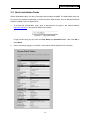
2.
After successfully logging in, machine current status will be displayed in the window.
- 10 -
AC1200R User’s Guide
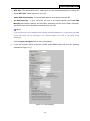
3.
Click the Setup Wizard on the left control menu to quickly configure your Router.
Figure 3-4
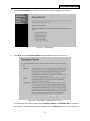
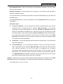
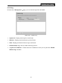
4.
Quick Setup
Click Next, and then Operation Mode page will appear, shown in Figure 3-5.
Figure 3-5
Quick Setup - WAN Connection Type
The Router provides three popular ways Gateway, Bridge and Wireless ISP to connect to
the Internet. It’s recommended that you make use of the Gateway function. If you are sure of
- 11 -
AC1200R User’s Guide
what kind of connection type your ISP provides, you can select the very type and click Next to
go on configuring.
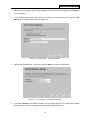
5.
If you are sure of what kind of NTP server your Router, you can select the very type and click
Next to go on configuring as shown in Figure 3-6.
Figure 3-6
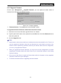
6.
Confirm the IP address for your Router and click Next to continue configuration.
Figure 3-7
7.
Quick Setup - Time Zone Setting
Quick Setup - LAN Interface Setting
If you select Gateway, the Router provides six connection types for your ISP provides. Make
sure the cable is securely plugged into the WAN port before continuing.
- 12 -
AC1200R User’s Guide
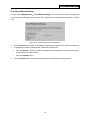
a)
If the connection type is PPPoE, then select it from drop down menu as shown below.
Enter the User Name and Password provided by your ISP, and click Next.
Figure 3-8
Quick Setup - WAN Interface Setting
User Name/Password - Enter the User Name and Password provided by your ISP.
These fields are case sensitive. If you have difficulty with this process, please contact
your ISP.
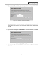
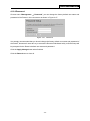
b) If the connection type detected is DHCP Client, the next screen will appear as shown in
Figure 3-9. You can then proceed with the wireless configuration.
Figure 3-9
Quick Setup - DHCP
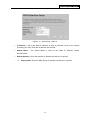
c) If the connection type detected is Static IP, the next screen will appear as shown in
Figure 3-10.
- 13 -
AC1200R User’s Guide
Figure 3-10
Quick Setup - Static IP
IP Address - This is the WAN IP address as seen by external users on the Internet
(including your ISP). Enter the IP address into the field.
Subnet Mask - The Subnet Mask is used for the WAN IP address, usually
255.255.255.0.
Default Gateway - Enter the gateway IP address into the box if required.
8.
Primary DNS - Enter the DNS Server IP address into the box if required.
- 14 -
AC1200R User’s Guide
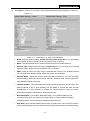
9.
Click Next to continue, the 2.4GHz / 5GHz Wireless settings page will appear as shown in
Figure 3-11.
Figure 3-11
Quick Setup – 2.4GHz / 5GHz Wireless
Band: Keep the default setting: 2.4GHz (B+G+N); 5GHz (A+N+AC). If you just want to
use a specific protocol, please use the drop down menu to select it.
Mode: This field determines the wireless mode which the AC1200R works on.
Network Type: Keep the default setting: Infrastructure. If you just want to use another
operation mode, please use the drop down menu to select it.
SSID: Create a unique and easy way to remember the name of your wireless network.
You can also keep default settings without the device being affected.
Channel Width - Select any channel width from the pull-down list. You can also keep
default settings without the device being affected. .Channel width can be adjusted to
meet different network scenarios.
Channel Number- This field determines which operating frequency will be used. The
default channel is set to Auto allowing the AC1200R to choose the best channel
automatically. It is not necessary to change the wireless channel unless you notice
interference problems with another nearby access point.
Broadcast SSID: If you enable “Broadcast SSID”, every wireless station in the
coverage of the router can discover its signal easily. In private network, disabling
“Broadcast SSID” can provide better wireless network security.
Data Rate: Set the wireless data transfer rate to a certain value. Since most of wireless
devices will negotiate with each other and pick a proper data transfer rate automatically,
- 15 -
AC1200R User’s Guide
it’s not necessary to change this value unless you know what will happen after
modification.
Associated Clients: Click the “Show Active Clients” button to show the status table of
active wireless clients.
Enable Universal Repeater Mode: Universal Repeater is a technology used to extend
wireless coverage. To enable Universal Repeater Mode, check the box and enter the
SSID you want to broadcast in the field below. Then please click “Security” submenu
for the related settings of the AP you want to connect to.
10. Set your security preference then click the Finished button.
Wireless Security: Recommend to choose WPA-PSK/WPA2-PSK and enter a Security Key
using ASCII characters between 8 and 63 characters or 64 hexadecimal characters in the
PSK Password filed. For advanced settings, please refer to Section 4.6: “Wireless”.
WPA-PSK/WPA2-PSK - Select WPA based on pre-shared passphrase.
PSK Password - You can enter ASCII or Hexadecimal characters.
For ASCII, the key can be made up of any numbers from 0 to 9 and any letters from
A to Z, the length should be between 8 and 63 characters.
For Hexadecimal, the key can be made up of any numbers 0 to 9 and letters A to F,
the length should be between 8 and 64 characters.
Please note the key is case sensitive, therefore the upper and lower case keys will
affect the outcome. It is highly recommended to write down the key and all related
wireless security settings.
Figure 3-12
Quick Setup - Finish
- 16 -
AC1200R User’s Guide
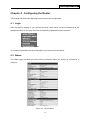
Chapter 4. Configuring the Router
This chapter will show each Web page's key functions and configuration.
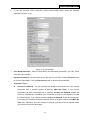
4.1 Login
After successfully logging in, you will see the seven main menus on the left hand-side of the
Web-based utility. On the right, there are corresponding explanations and instructions.
Figure 4-1 the main menu
The detailed explanations for each Web page’s key function are listed below.
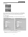
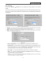
4.2 Status
The Status page provides the current status information about the Router. All information is
read-only.
Figure 4-2
Router Status
- 17 -
AC1200R User’s Guide
4.3 Quick Setup
Please refer to Section 3.2: "Quick Installation Guide".
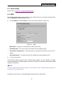
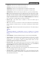
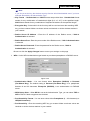
4.4 WPS
This section will help guide you into adding a new wireless device to an existing network quickly
with the WPS (Wi-Fi Protect Setup) function.
a)
Choose WPS from the Security menu in the next screen (shown in Figure 4-3 ).
Figure 4-3 WPS
WPS Status - Configure or Unconfigure the WPS function here.
Self-PIN Number - The current value of the Router's PIN is displayed here.
Push Button Configuration – Push this button to synchronize the Router and your Wi-Fi
adapter
b)
Client PIN Number – To synchronize the Wi-Fi adapter by entering adapter’s PIN.
To add a new device:
If the wireless adapter supports Wi-Fi Protected Setup (WPS), you can establish a wireless
connection between the wireless adapter and Router using either Push Button Configuration (PBC)
method or PIN method.
Note:
To build a successful connection by WPS, you should also do the corresponding configuration of
the new device for WPS function.
Configuring a new device (ex. AWUS036NHR), please follow the steps below.
- 18 -
AC1200R User’s Guide
Step 1: Press PBC button from the Wireless LAN Utility then the Wi-Fi Protected Setup – PBC
method will pop up and wait for an authentication.
Step 2: Press Start PBC button on your Router for authentication.
Step 3: Wait for a minute then you’ll discover your AWUS036NHR is connected to AC1200R
automatically.
- 19 -
AC1200R User’s Guide
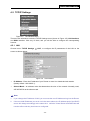
4.5 TCP/IP Settings
Figure 4-5 The Network Menu
There are two submenus under the TCP/IP Settings menu (shown in Figure 4-5): LAN Interface,
and WAN Interface. Click any of them, and you will be able to configure the corresponding
function.
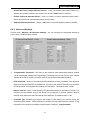
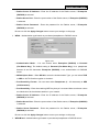
4.5.1 LAN
Choose menu “TCP/IP Settings → LAN”, to configure the IP parameters of the LAN on the
screen as shown below.
Figure 4-6
LAN Interface
IP Address - Enter the IP address of your Router or reset it in dotted-decimal notation
(factory default: 192.168.26.1).
Subnet Mask - An address code that determines the size of the network. Normally used,
255.255.255.0 as the subnet mask.
Note:
1.
If you change the IP Address of LAN, you must use the new IP Address to log into the Router.
2.
If the new LAN IP Address you set is not in the same subnet, the IP Address pool of the DHCP
server will change accordingly at the same time,while the Virtual Server and DMZ Host will
not take effect until they have been re-configured.
- 20 -
AC1200R User’s Guide
Default Gateway - Enter the gateway IP address in dotted-decimal notation provided by your
system administrator.
DHCP – Select Disabled, Client or Server in different operation mode for AC1200R
DHCP Client Range - Fill in the start IP address and end IP address to allocate a range of IP
addresses; client with DHCP function set will be assigned an IP address automatically.
Show Client – Press open to active the DHCP Client Table window that shows the active
clients with their assigned IP address, MAC address and time expired information. [Server
mode only]
DHCP Lease Time – Amount of time the IP address is leased for.
Set Static DHCP - Manual setup Static DHCP IP address for specific MAC address. [Server
mode only]
Domain Name - Assign Domain Name and dispatch to DHCP clients [optional]
802.1d Spanning Tree - Enable or disable the IEEE 802.1d Spanning Tree function from
pull-down menu.
Clone MAC Address - Fill in the MAC address for the MAC address to be cloned.
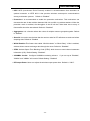
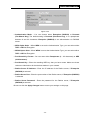
4.5.2 WAN Interface
Choose menu “TCP/IP Settings → WAN”, you can configure the IP parameters of the WAN on
the screen shown below.
Figure 4-7 WAN – Static IP
- 21 -
AC1200R User’s Guide
1.
Clone MAC Address - Fill in the MAC address for the MAC address to be cloned
Enable uPNP - Click the checkbox to enable uPNP function.
Enable IGMP Proxy - Click the checkbox to enable IGMP proxy
Enable Ping Access on WAN - Click the checkbox to enable WAN IGMP response.
Enable Web server Access on WAN - Click the checkbox to enable web configuration from
Enable IPsec pass through on VPN connection - Click the checkbox to enable IPSec
packet pass through
Enable PPTP pass through on VPN connection - Click the checkbox to enable PPTP
packet pass through
Enable L2TP pass through on VPN connection - Click the checkbox to enable L2TP packet
pass through
If your ISP provides a static or fixed IP Address, Subnet Mask, Gateway and DNS setting,
select Static IP. The Static IP settings page will appear, shown in Figure 4-7.
IP Address - Enter the IP address in dotted-decimal notation provided by your ISP.
Subnet Mask - Enter the subnet Mask in dotted-decimal notation provided by your ISP,
usually 255.255.255.0.
Default Gateway - (Optional) Enter the gateway IP address in dotted-decimal notation
provided by your ISP.
MTU Size - The normal MTU (Maximum Transmission Unit) value for most Ethernet
networks is 1500 Bytes. It is not recommended that you change the default MTU Size
unless required by your ISP.
DNS 1 / DNS 2 / DNS 3 - (Optional) Enter one or two DNS addresses in dotted-decimal
notation provided by your ISP.
Click the Apply Changes button to save your settings.
2.
If your ISP provides the DHCP service, please choose DHCP Client type, and the Router will
automatically get IP parameters from your ISP (shown in Figure 4-8).
- 22 -
AC1200R User’s Guide
Figure 4-8
WAN – Dynamic IP
Host Name – Enter the host name provided by your ISP, default value is blank.
MTU Size - The normal MTU (Maximum Transmission Unit) value for most Ethernet networks
is 1500 Bytes. It is not recommended that you change the default MTU Size unless required
by your ISP.
Attain DNS Automatically – Receives DNS address automatically from the ISP.
Set DNS Manually - If your ISP gives you one or two DNS addresses, select Set DNS
Manually and enter the primary and secondary addresses into the correct fields. Otherwise,
the DNS servers will be assigned dynamically from your ISP.
Note:
If you find an error message on the website after entering the DNS addresses, it is likely that
your DNS server has been set up improperly. You should contact your ISP to get DNS server
addresses.
3.
If your ISP provides a PPPoE connection, select PPPoE option and enter the following
parameters (Figure 4-9):
- 23 -
AC1200R User’s Guide
Figure 4-9
WAN - PPPoE
User Name/Password - Enter the User Name and Password provided by your ISP. These
fields are case-sensitive.
Service Name - The service name should not be configured unless you are sure it is
necessary for your ISP. In most cases, leaving these fields blank.
Connection Type
Continuous – Continuous connection type means to setup the connection through
PPPoE protocol whenever this WLAN Broadband Router is powered on.
Connect on Demand – In this mode, the Internet connection can be terminated
automatically after a specified inactivity period (Max Idle Time) and be re-established
when you attempt to access the Internet again.
Manual - You can click the Connect/Disconnect button to connect/disconnect
immediately. This mode also supports the Max Idle Time function as Connect on
Demand mode. The Internet connection can be disconnected automatically after a
specified inactivity period and re-established when you attempt to access the Internet
again.
Caution: Sometimes the connection cannot be terminated although you specify a time
to Max Idle Time because some applications are visiting the Internet continually in the
background.
Idle Time - If you want your Internet connection to be active constantly, please enter “0” in the
Max Idle Time field. Otherwise, enter the number of minutes you want to have elapsed before
your Internet access disconnects.
- 24 -
AC1200R User’s Guide
MTU Size - The default MTU size is “1480” bytes. It is not recommended that you change the
default MTU Size unless required by your ISP.
Attain DNS Automatically – Receives DNS address automatically from the ISP.
Set DNS Manually - If your ISP gives you one or two DNS address, select Set DNS
Manually and enter the primary and secondary addresses into the correct fields. Otherwise,
the DNS servers will be assigned dynamically from your ISP.
Note:
If you find an error on the website after entering the DNS addresses, it is likely that your DNS
server has been set up improperly. You should contact your ISP to get DNS server
addresses.
Click the Apply Changes button to save your settings.
4.
If your ISP provides PPTP connection, please select PPTP option and enter the following
parameters (Figure 4-11):
Figure 4-11 L2TP Settings
- 25 -
AC1200R User’s Guide
User Name/Password - Enter the User Name and Password provided by your ISP. These
fields are case-sensitive.
Dynamic IP/ Static IP - Choose either as you are given by your ISP and enter the ISP’s IP
address or the domain name.
If you choose static IP, enter the domain name and enter the DNS assigned by your ISP. Click
the Save button.
Click the Connect button to connect immediately. Click the Disconnect button to disconnect
immediately.
Connection Type –
Connect on Demand - You can configure the Router to disconnect from your Internet
connection after a specified period of inactivity (Max Idle Time). If your Internet
connection has been terminated due to inactivity, Connect on Demand enables the
Router to automatically re-establish your connection as soon as you attempt to access
the Internet again. If you wish to activate Connect on Demand, check the radio button.
If you want your Internet connection to remain active at all times, enter “0” in the Max
Idle Time field. Otherwise, enter the number of minutes you want to have elapsed before
your Internet connection terminates.
Continuous - Connect automatically after the Router is disconnected. To use this option,
check the radio button.
Connect Manually - You can configure the Router to connect or disconnect manually.
After a specified period of inactivity (Max Idle Time), the Router will disconnect from
your Internet connection. You will not be able to re-establish your connection
automatically when attempting to access the Internet again. To use this option, click the
radio button. If you want your Internet connection to remain active at all times, enter "0"
in the Max Idle Time field. Otherwise, enter the number in minutes that you wish to have
the Internet connecting last unless a new link is requested.
Caution: Sometimes the connection cannot be disconnected although you specify a time to Max
Idle Time because some applications are visiting the Internet continually in the background.
Click the Save button to save your settings.
- 26 -
AC1200R User’s Guide
5.
If your ISP provides L2TP connection, please select L2TP option. Enter the following
parameters (Figure 4-12):
Figure 4-12 L2TP Settings
User Name/Password - Enter the User Name and Password provided by your ISP. These
fields are case-sensitive.
Dynamic IP/ Static IP - Choose either as you are given by your ISP. Click the Connect button
to connect immediately. Click the Disconnect button to disconnect immediately.
Connection Type –
Connect on Demand - You can configure the Router to disconnect from your Internet
connection after a specified period of inactivity (Max Idle Time). If your Internet
connection has been terminated due to inactivity, Connect on Demand enables the
Router to automatically re-establish your connection as soon as you attempt to access
the Internet again. If you wish to activate Connect on Demand, check the radio button.
If you want your Internet connection to remain active at all times, enter 0 in the Max Idle
Time field. Otherwise, enter the number of minutes you want to have elapsed before
your Internet connection terminates.
- 27 -
AC1200R User’s Guide
Continuous - Connect automatically after the Router is disconnected. To use this option,
check the radio button.
Connect Manually - You can configure the Router to connect or disconnect manually.
After a specified period of inactivity (Max Idle Time), the Router will disconnect from
your Internet connection, and you will not be able to re-establish your connection
automatically when attempting to access the Internet again. To use this option, check the
radio button. If you want your Internet connection to remain active at all times, enter "0"
in the Max Idle Time field. Otherwise, enter the number of minutes that you wish to have
the Internet connecting last unless a new link is requested.
Caution: Sometimes the connection cannot be disconnected although you specify a time to Max
Idle Time, because some applications are visiting the Internet continually in the background.
Click the Save button to save your settings.
- 28 -
AC1200R User’s Guide
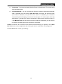
4.6 Wireless
Figure 4-15 Wireless menu
There are eight submenus under the Wireless menu (shown in Figure 4-15): Basic Settings,
Advanced Settings, Security, Access Control, WDS Setting, Site Survey, WPS, and
Schedule. Click any of them, and you will be able to configure the corresponding function.
4.6.1 Basic Settings
Choose menu “Wireless → Basic Settings”, you can configure the basic settings for the 2.4GHz
/ 5GHz wireless network.
Figure 4-16 Wireless Settings
Band - Select the desired protocol. The default setting is 2.4GHz (B+G+N).
2.4GHz (B) - Select if all of your wireless clients are 802.11b.
- 29 -
AC1200R User’s Guide
2.4GHZ (G) - Select if all of your wireless clients are 802.11g.
2.4GHz (N) - Select if all of your wireless clients are 802.11n.
2.4GHz (B+G) - Select if you are using both 802.11b and 802.11g wireless clients.
2.4GHz (G+N) - Select if you are using both 802.11g and 802.11n wireless clients.
2.4GHz (B+G+N) – Select if you are using a mix of 802.11b, 11g, and 11n wireless clients.
Mode - Select the desired wireless mode. AC1200R offers AP, Client, WDS, and AP + WDS.
When 802.11g mode is selected, only 802.11g wireless stations can connect to the Router.
When 802.11n mode is selected, only 802.11n wireless stations can connect to the AP. It is
strongly recommended that you set the Mode to 2.4GHz (B+G+N) and all of 802.11b,
802.11g, and 802.11n wireless stations can connect to the Router.
Network Type - After network mode is selected to “Client” set network type as
infrastructure or Ad-Hoc.
SSID - Enter a value of up to 32 characters. The same name of SSID (Service Set Identification)
must be assigned to all wireless devices in your network. Considering your wireless network
security.
Channel width - Select the channel width from the pull-down list. The default setting is
40MHz.
Note:
If 2.4GHz (B), 2.4GHz (G), or 2.4GHz (B+G) is selected in the Mode field, the Channel
Width selecting field will disappear and the value will become 20M, which is unable to be
changed.
Control Sideband – Select the sideband with upper or lower for channel width 40MHz.
Channel Number- This field determines which operating frequency will be used. The default
channel is CH11. You can set to Auto where the AP will choose the best channel
automatically, it is not necessary to change the wireless channel unless you notice
interference problems with another nearby access point.
Broadcast SSID - When wireless clients survey the local area for wireless networks to
associate with, they will detect the SSID broadcast by the Router. If you select Enable for
Broadcast SSID then Router will broadcast its name (SSID) on the air.
WMM – Click on Enable or Disable Wireless Multimedia (WMM).
Data Rate - Select transmission data rate from pull-down menu. Data rate can be auto
select, 1M to 54Mbps or MCS. The default option is AUTO.
Associate Clients – Click Show Active Clients button to open Active Wireless Client Table
that shows the MAC address, transmit-packet, receive-packet and transmission-rate for
each associated wireless client.
- 30 -
AC1200R User’s Guide
Enable Mac Clone (Single Ethernet Client) – Copy your system’s NIC MAC address as
wireless client’s MAC address, this function only works if Client mode is selected.
Enable Universal Repeater Mode – Check to enable Universal Repeater Mode where
Router acts as AP and client simultaneously in this mode).
SSID for Extended Interface – Assign a SSID when Universal Repeater Mode is enabled.
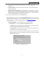
4.6.2 Advanced Settings
Choose menu “Wireless → Advanced Settings”, you can configure the advanced settings of
your 2.4GHz / 5GHz wireless network.
Fragmentation Threshold - This value is the maximum size determining whether packets
will be fragmented. Setting the Fragmentation Threshold too low may result in poor network
performance due to excessive packets, 2346 is the recommended default setting.
RTS Threshold - Here you can specify the RTS (Request to Send) Threshold. If the packet is
larger than the specified RTS Threshold size, the Router will send RTS frames to a particular
receiving station and negotiate the sending of a data frame. The default value is 2346.
Beacon Interval - Enter a value between 20-1000 milliseconds for the Beacon Interval. The
beacons are the packets sent by the Router to synchronize a wireless network. Beacon
Interval value determines the time interval of the beacons. The default value is 100.
Preamble Type Preamble type defines the length of CRC block in the frames during the
wireless communication. “Short Preamble” is suitable for high traffic wireless network. “Long
Preamble” can provide more reliable communication. Default is “Long Preamble”.
- 31 -
AC1200R User’s Guide
IAPP IAPP (Inter-Access Point Protocol) enabled is recommendation that describes an
optional extension to IEEE 802.11 that provides wireless access-point communications
among multivendor systems. Default is “Enabled”.
Protection It is recommended to enable the protection mechanism. This mechanism can
decrease the rate of data collision between 802.11b and 802.11g wireless stations. When the
protection mode is enabled, the throughput of the AP will be a little lower due to many of
frame traffic should be transmitted. Default is “Disabled”
Aggregation It is a function where the values of multiple rows are grouped together. Default
is “Enabled”
Short GI It is used to set the time that the receiver waits for RF reflections to settle out before
sampling data. Default is “Enabled
WLAN Partition This feature also called “WLAN isolation” or “Block Relay”. If this is enabled,
wireless clients cannot exchange data through the router. Default is “Disabled".
STBC Activate Space Time Blocking Code (STBC) which does not need channel statement
information (CSI). Default Setting: "Disabled"
20/40MHz Coexist Configure 20/40MHz coexisting scheme. If you set up as "Enabled",
"20MHz" and "40MHz" will coexist. Default Setting: "Disabled"
RF Output Power Users can adjust the wireless output power here. Default is “100%”.
- 32 -
AC1200R User’s Guide
4.6.3 Security
Choose menu “Wireless → Security”, you can configure the security settings of your wireless
network.
There are four wireless security modes supported by the Router: WEP (Wired Equivalent Privacy),
WPA (Wi-Fi Protected Access), WPA2 (Wi-Fi Protected Access 2), WPA-Mixed (Pre-Shared Key
or Enterprise).
Figure 4-18 Wireless Security
Disable - If you do not want to use wireless security, check this radio button. It’s strongly
recommended to choose one of the following modes to enable security.
WEP - It is based on the IEEE 802.11 standard. If you check this radio button, you will find a
notice in red as shown in Figure 4-19.
Figure 4-19
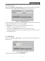
802.1x Authentication – Check to enable 802.1x authentication via RADIUS server.
Authentication - You can choose the type for the WEP security on the pull-down list. The
default setting is Auto, which can select Shared Key or Open System authentication type
automatically based on the wireless station's capability and request.
Key Length - You can select the WEP key length (64-bit, or 128-bit) for encryption.
64-bit - You can enter 10 hexadecimal digits (any combination of 0-9, a-f, A-F, zero key is
not recommended) or 5 ASCII characters.
128-bit - You can enter 26 hexadecimal digits (any combination of 0-9, a-f, A-F, zero key is
not recommended) or 13 ASCII characters.
- 33 -
AC1200R User’s Guide
Note:
If you do not set the key, the wireless security function will still be disabled even if you have
selected Shared Key as Authentication Type.
Key Format - Hexadecimal and ASCII formats are provided here. Hexadecimal format
stands for any combination of hexadecimal digits (0-9, a-f, A-F) in the specified length.
ASCII format stands for any combination of keyboard characters in the specified length.
Encryption Key - Select which of the four keys will be used and enter the matching WEP
key you have created. Make sure these values are identical on all the wireless stations in
your network.
Radius Server IP Address - Enter the IP address of the Radius server, if 802.1x
Authentication is selected.
Radius Server Port - Enter the port number of the Radius server, if 802.1x Authentication
is selected.
Radius Server Password - Enter the password for the Radius server, if 802.1x
Authentication is selected.
Be sure to click the Apply Changes button to save your settings on this page
WPA - It’s the WPA authentication type based on pre-shared passphrase or RADIUS server.
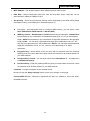
Figure 4-20
Authentication Mode - You can choose either Enterprise (RADIUS) or Personal
(Pre-Shared Key). The default setting is Personal (Pre-Share Key), it’s a passphrase
between 8 and 63 characters. Enterprise (RADIUS), is an authentication via RADIUS
server.
WPA Cipher Suite - When WPA is set as the Authentication Type, you can select TKIP or
AES or AUTO if both encryptions are checked.
Pre-Shared Key Format - You can enter chose either Passphrase (8 ~ 63 characters) or
HEX(64 Characters).
Pre-Shared Key - Enter the matching WEP key you created. Make sure these values are
identical on all the wireless stations in your network.
- 34 -
AC1200R User’s Guide
Radius Server IP Address - Enter the IP address of the Radius server, if Enterprise
(RADIUS) is selected.
Radius Server Port - Enter the port number of the Radius server, if Enterprise (RADIUS)
is selected.
Radius Server Password - Enter the password for the Radius server, if Enterprise
(RADIUS) is selected.
Be sure to click the Apply Changes button to save your settings on this page.
WPA2 - Authentication type based on pre-shared passphrase or RADIUS server.
Figure 4-21
Authentication Mode - You can choose either Enterprise (RADIUS) or Personal
(Pre-Shared Key). The default setting is Personal (Pre-Share Key), it’s a passphrase
between 8 and 63 characters. Enterprise (RADIUS), is an authentication via RADIUS
server.
WPA2 Cipher Suite - When WPA2 is set as the Authentication Type, you can select TKIP
or AES or AUTO if both encryption is checked..
Pre-Shared Key Format - You can enter either Passphrase (8 ~ 63 characters) or HEX
(64 Characters).
Pre-Shared Key - Enter the matching WEP key that you’ve create. Make sure these values
are identical on all the wireless stations in your network.
Radius Server IP Address - Enter the IP address of the Radius server, if Enterprise
(RADIUS) is selected.
Radius Server Port - Enter the port number of the Radius server, if Enterprise (RADIUS)
is selected.
Radius Server Password - Enter the password for the Radius server, if Enterprise
(RADIUS) is selected.
Be sure to click the Apply Changes button to save your settings on this page.
WPA-Mixed - Authentication type based on pre-shared passphrase or RADIUS server.
- 35 -
AC1200R User’s Guide
Figure 4-22
Authentication Mode - You can choose either Enterprise (RADIUS) or Personal
(Pre-Shared Key). The default setting is Personal (Pre-Share Key), it is a passphrase
between 8 and 63 characters. Enterprise (RADIUS) is an authentication via RADIUS
server.
WPA Cipher Suite - When WPA is set as the Authentication Type, you can select either
TKIP or AES as Encryption.
WPA2 Cipher Suite - When WPA2 is set as the Authentication Type, you can select either
TKIP or AES as Encryption.
Pre-Shared Key Format - You can enter either Passphrase (8 ~ 63 characters) or HEX
(64 Characters).
Pre-Shared Key - Enter the matching WEP key that you have create. Make sure these
values are identical on all the wireless stations in your network.
Radius Server IP Address - Enter the IP address of the Radius server, if Enterprise
(RADIUS) is selected.
Radius Server Port - Enter the port number of the Radius server, if Enterprise (RADIUS)
is selected.
Radius Server Password - Enter the password for the Radius server, if Enterprise
(RADIUS) is selected.
Be sure to click the Apply Changes button to save your settings on this page.
- 36 -
AC1200R User’s Guide
4.6.4 Access Control
Choose menu “Wireless → Access Control”, you can control the 2.4GHz / 5GHz wireless
access by configuring the Wireless Access Control function, shown in Figure 4-23.
Figure 4-23 Wireless Access Control
To allow wireless users by MAC Address, click Allow Listed, or prohibited wireless users by MAC
Address by click Deny Listed. The default setting is Disable.
MAC Address - The wireless station's MAC address that you want to filter.
Comment - A simple description of the wireless station.
Be sure to click the Apply Changes button to save your settings on this page
Current Access Control List - Displays the registered clients that are allowed to link to this
WLAN Broadband Router.
4.6.5 WDS Settings
Choose menu “Wireless → WDS Settings”, you can configure the advanced settings of your
wireless network.
Figure 4-24 Wireless Advanced
To add wireless AP by MAC Address, click Enable WDS.
- 37 -
AC1200R User’s Guide
MAC Address - The wireless station's MAC address that you want to add.
Data Rate - Select transmission data rate from the drop down menu. Data rate can be
auto-selected, 1Mbps to 54Mbps or MCS.
Set Security - There are two wireless security modes supported by the WDS: WEP (Wired
Equivalent Privacy), and WPA2 (Wi-Fi Protected Access 2).
Encryption – Use drop down menu to configure WDS security, you can select it from
None, WEP 64-bits, WEP 128-bits, or WPA2 (AES).
WEP Key Format – Hexadecimal and ASCII formats are provided here. Hexadecimal
format stands for any combination of hexadecimal digits (0-9, a-f, A-F) in the specified
length. ASCII format stands for any combination of keyboard characters in the specified
length. 64-bit - You can enter 10 hexadecimal digits (any combination of 0-9, a-f, A-F,
zero key is not promoted) or 5 ASCII characters. 128-bit - You can enter 26 hexadecimal
digits (any combination of 0-9, a-f, A-F, zero key is not promoted) or 13 ASCII
characters.
Encryption Key - Select which of the four keys will be used and enter the matching
WEP key that you create. Make sure these values are identical on all wireless stations in
your WDS network
Pre-Shared Key Format - You can enter chose either Passphrase (8 ~ 63 characters)
or HEX(64 Characters).
Pre-Shared Key - Enter the matching WEP key that you create. Make sure these values
are identical on all wireless stations in your WDS network
Comment - A simple description of the wireless station.
Be sure to click the Apply Changes button to save your settings on this page
Current WDS AP List - Displays the registered APs that are allowed to link to this WLAN
Broadband Router.
- 38 -
AC1200R User’s Guide
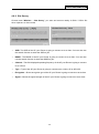
4.6.6 Site Survey
Choose menu “Wireless → Site Survey”, you scan and connect nearby 2.4GHz / 5GHz APs
when operate at client mode.
SSID- The SSID of the AP your Router is going to connect to as a client. You can also use
the search function to select the SSID to join.
BSSID - The BSSID of the AP your Router is going to connect to as a client. You can also
use the search function to select the BSSID to join.
Channel - This field displayed operating frequency of the AP your Router is going to connect
to as a client.
Type – Type of the AP your Router is going to connect to as a client, AP or AD-HOC.
Encryption – Shows encryption type of the AP your Router is going to connect to as a client.
Signal – Shows the signal strength of the AP your Router is going to connect to as a client.
- 39 -
AC1200R User’s Guide
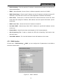
4.6.7 WPS
Choose menu “Wireless → WPS”, where you to add a new wireless device to an existing
2.4GHz or 5GHz network quickly.
Self-PIN Number - The current value of the Router's PIN is displayed here.
PIN Configuration - You will need to enter Self-PIN Number into adapter’s configuration
utility or on the adapter itself. Press the Start PIN button on the router and on the adapter.
Note: You will have two minutes to push the PIN button on the router and device(s) you want
to connect.
Push Button Configuration - You will need an adapter that supports it via a utility or on the
adapter itself. Press the Start PBC button on the router and on the adapter.
Note: You will have two minutes to push the PIN button on the router and device(s) you want
to connect.
- 40 -
AC1200R User’s Guide
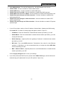
4.6.8 Schedule
Choose menu “Wireless → Schedule”, time period allowed for the PC controlled to access the
Internet.
Figure 4-25 Schedule
- 41 -
AC1200R User’s Guide
4.7 Firewall
Figure 4-26 The Firewall menu
There are submenus under the Firewall menu (shown in Figure 4-26). Click any of them, and you
will be able to configure the corresponding function.
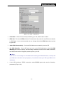
4.7.1 Port Filtering
Choose menu “Firewall → Port Filtering”, you can control the wireless access by configuring
the Port Filtering function as shown in Figure 4-27.
Figure 4-27 Port Filtering
Enable Port Filtering – Check to Enable port filtering feature.
Port Range / Protocol / Comment - Specify the port range from start-port to end-port and
put your comment to remind you why you have restriction on these ports. You can restricted
TCP, UDP, or both protocol.
Be sure to click the Apply Changes button to save your settings on this page
- 42 -
AC1200R User’s Guide
4.7.2 IP Filtering
Choose menu “Firewall → IP Filtering”, you can control the wireless access by configuring the
IP Filtering function as shown in Figure 4-28.
Figure 4-28
IP Filtering
Enable IP Filtering – Check to Enable IP filtering feature.
Local IP Address / Protocol / Comment - Specify the local IP address that you wish to put
restriction and mark your comment to remind you why you have restriction on this IP address.
You can restrict the traffic from TCP, UDP, or both protocol.
Be sure to click the Apply Changes button to save your settings on this page
4.7.3 MAC Filtering
Choose menu “Firewall → MAC Filtering”, you can control the wireless access by configuring
the MAC Filtering function as shown in Figure 4-29.
Figure 4-29
MAC Filtering
- 43 -
AC1200R User’s Guide
Enable MAC Filtering – Check to Enable MAC filtering feature.
MAC Address - The wireless station's MAC address that you want to filter.
Be sure to click the Apply Changes button to save your settings on this page.
4.7.4 Port Forwarding
Choose menu “Firewall → Port Forwarding”, you can redirect the network traffic by configuring
the Port Forwarding function as shown in Figure 4-30.
Figure 4-30 Port Forwarding
Enable Port Forwarding – Check to Enable port forwarding feature.
IP Address – Forward data packets to specific IP address in your local area network.
Protocol - The protocol used for forwarding data packets, either TCP or UDP, or BOTH
Port Range - The port range used by the remote system when it responds to the forwarding
request. A response using one of these ports will be forwarded to the PC that triggered this
rule.
Be sure to click the Apply Changes button to save your settings on this page.
- 44 -
AC1200R User’s Guide
4.7.5 URL Filtering
Choose menu “Firewall → URL Filtering”, you can restrict user to access specific web page by
configuring the URL Filtering function as shown in Figure 4-31.
Figure 4-31
URL Filtering
Enable URL Filtering – Check to Enable URL filtering feature.
URL Address - The address that you want to restrict user to access.
Be sure to click the Apply Changes button to save your settings on this page.
4.7.6 DMZ
Choose menu “Firewall → DMZ”, you can view and configure DMZ host in the screen as shown
in Figure 4-32. The DMZ host feature allows one local host to be exposed to the Internet for a
special-purpose service such as Internet gaming or videoconferencing. DMZ host forwards all the
ports at the same time. Any PC whose port is being forwarded must have its DHCP client function
disabled and should have a new static IP Address assigned to it because its IP Address may be
changed when using the DHCP function.
Figure 4-32
- 45 -
DMZ
AC1200R User’s Guide
To assign a computer or server to be a DMZ server:
1.
Check the Enable DMZ checkbox.
2.
Enter the IP Address of a local host in the DMZ Host IP Address field.
3.
Click the Apply Changes button.
Note:
After you set the DMZ host, the firewall related to the host will not work.
4.7.7 VLAN
Choose menu “Firewall → VLAN”, if you want to configure the Guest and Internal networks on
VLAN, the switch you are using must support VLAN. As a prerequisite step, configure a port on the
switch for handling VLAN tagged packets as described in the IEEE802.1Q standard, and enable
this field as shown in Figure 4-33.
Figure 4-33
VLAN
Be sure to click the Apply Changes button to save your settings on this page.
- 46 -
AC1200R User’s Guide
4.8 QoS
The QoS (Quality of Service) helps improve your network gaming performance by prioritizing
applications. By default the bandwidth control are disabled and application priority is not classified
automatically. In order to complete this settings, please follow the steps below.
1. Enable this function.
2. Enter the total speed or choose automatic mode.
3. Enter the IP address or MAC address user want to control.
4. Specify how to control this PC with this IP address or MAC address, including maximum or
minimum bandwidth, priority and its up/down speed. After the configuration, please click the
“Apply” button to save the settings.
Figure 4-34 The QoS menu
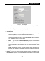
4.9 Route Setup
Static routing is a special type of routing that can be applied in a network to reduce the problem of
routing selection and data flow overload caused by routing selection so as to improve the packets
forwarding speed. You can set the destination IP address, subnet mask, and gateway to specify a
routing rule. The destination IP address and subnet mask determine a destination network or host
to which the router sends packets through the gateway.
- 47 -
AC1200R User’s Guide
Enable Dynamic Route Click this box to enable Dynamic Route.
Transmit enable RIPv1 or RIPv2 protocol on outgoing data.
Receive enable RIPv1 or RIPv2 protocol on incoming data.
Enable Static Route Click this box to enable static route.
IP Address The network or host IP address desired to access.
Subnet Mask The subnet mask of destination IP.
Gateway The gateway is the router or host’s IP address to which packet was sent. It must
be the same network segment with the WAN or LAN port.
Show Routing Table Clicking this button will show you all the routing table of the system.
Static Routing table It only shows the static routing table and you can delete one or all.
Figure 4-35 Route setup menu
- 48 -
AC1200R User’s Guide
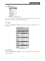
4.10 Management
Figure 4-35 The Management menu
There are nine submenus under the Management menu as shown in Figure 4-35. Click any of
them, and you will be able to configure the corresponding function.
4.10.1 Status
Choose menu “Management → Status”, display the current status of AC1200R as shown in
Figure 4-39.
Figure 4-35 Status
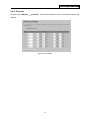
4.10.2 Statistics
Choose menu “Management → Statistics”, you can view the network traffic on the Router as
shown in Figure 4-36.
- 49 -
AC1200R User’s Guide
Figure 4-36 Statistics
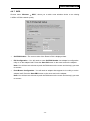
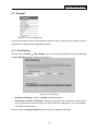
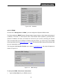
4.10.3 DDNS
Choose menu “Management -> DDNS”, you can configure the Dynamic DNS function.
The Router offers the DDNS (Dynamic Domain Name System) feature, which allows the hosting of
a website, FTP server, or e-mail server with a fixed domain name (named by yourself) and a
dynamic IP address, and then your friends can connect to your server by entering your domain
name no matter what your IP address is. Before using this feature, you need to sign up for DDNS
service providers such as www.dyndns.org, or TZO. The Dynamic DNS client service provider will
give you a password or key.
If the dynamic DNS Service Provider your select is www.dyndns.org, the page will appear as
shown in Figure 4-41.
Figure 4-41
DNS Settings
To set up for DDNS, follow these instructions:
1.
Type the User Name for your DDNS account.
- 50 -
AC1200R User’s Guide
2.
Type the Password for your DDNS account.
3.
Type the Domain Name you received from dynamic DNS service provider here.
4.
Click the Apply Change button to log in to the DDNS service.
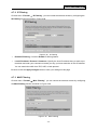
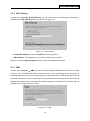
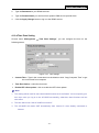
4.10.4 Time Zone Setting
Choose menu “Management → Time Zone Settings”, you can configure the time on the
following screen.
Figure 4-42
Time settings
Current Time – Type in the current time into the blanks or click “Copy Computer Time” to get
the current time from computer.
Time Zone Select – select the time zone.
Enable NTP client update – click to enable the NTP client update.
Note:
1. This setting will be used for some time-based functions such as firewall. You must specify your
time zone once you log in to the AC1200R successfully, otherwise, these functions will not
take effect.
2. The time will be lost if the AC1200R is turned off.
3. The AC1200R will obtain GMT automatically from Internet if it has already connected to
Internet.
- 51 -
AC1200R User’s Guide
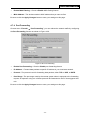
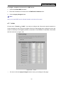
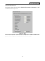
4.10.5 Denial-of-Service
DoS Protection will take effect only when the Enable DoS Preventation in “Management → DoS”
is enabled as shown in Figure 4-43.
Figure 4-43
DoS
Denial of Service protection. Check the Enable or Disable button to enable or disable the DoS
protection function. Only when it is enabled, will the flood filters be enabled.
- 52 -
AC1200R User’s Guide
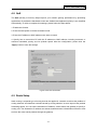
4.10.6 Log
Choose menu “Management →Log”, you can view the logs of the AC1200R.
Figure 4-44
System Log
System all – Display all the log file on the Router .
Wireless – Display just the wireless log on the Router.
DoS – Display just Denial-of-Service log on the Router.
Enable Remote Log - Click to enable remote log service.
Log Server IP Address – Please enter the IP address to store your log file when Enable
Remote Log is enabled.
- 53 -
AC1200R User’s Guide
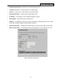
4.10.7 Upgrade Firmware
Choose menu “Management → Upgrade Firmware”, you can update the latest version of
firmware for the Router on the following screen.
Figure 4-45
Firmware Upgrade
Firmware Version - This displays the current firmware version.
To upgrade the Router's firmware, follow these instructions below:
1. Download a more recent firmware upgrade file from our website.
2. Type the path and file name of the update file into the File field. Or click the Browse button to
locate the update file.
3. Click the Upgrade button.
Note:
1.
New firmware versions are posted at our website and can be downloaded for free. There is no
need to upgrade the firmware unless the new firmware has a new feature you want to use.
However, when experiencing problems caused by the Router rather than the configuration,
you can try to upgrade the firmware.
2.
When you upgrade the Router's firmware, you may lose its current configurations, so before
upgrading the firmware please write down some of your customized settings to avoid losing
important settings.
3.
Do not turn off the Router or press the Reset button while the firmware is being upgraded,
otherwise, the Router may be damaged.
4.
The Router will reboot after the upgrading has been finished.
- 54 -
AC1200R User’s Guide
4.10.8 Save/Reload Setting
Choose menu “Management → Save/Reload Setting”, you can save the current configuration
of the Router as a backup file and restore the configuration via a backup file as shown in Figure
4-46.
Figure 4-46
Backup & Restore Configuration
Click the Save button to save all configuration settings as a backup file in your local computer.
To upgrade the Router's configuration, follow these instructions.
Click the Browse… button to locate the update file for the Router, or enter the exact path
to the Setting file in the text box.
Click the Upload button.
Click the Reset button restore the configurations of the Router to factory defaults.
- 55 -
AC1200R User’s Guide
4.10.9 Password
Choose menu “Management → Password”, you can change the factory default user name and
password of the Router in the next screen as shown in Figure 4-47.
Figure 4-47
Password
It is strongly recommended that you should change the factory default user name and password of
the Router, because all users who try to access the Router's Web-based utility or Quick Setup will
be prompted for the Router's default user name and password.
Click the Apply Change button when finished.
Click the Reset button to clear all.
- 56 -
AC1200R User’s Guide
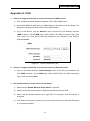
Appendix A: FAQ
1.
How do I configure the Router to access the Internet by ADSL users?
1)
First, configure the ADSL Modem configured in RFC1483 bridge model.
2)
Connect the Ethernet cable from your ADSL Modem to the WAN port on the Router. The
telephone cord plugs into the Line port of the ADSL Modem.
3)
Log in to the Router, click the “Network” menu on the left of your browser, and click
"WAN" submenu. On the WAN page, select “PPPoE” for WAN Connection Type. Type
user name in the “User Name” field and password in the “Password” field, finish by
clicking Connect.
Figure A-1 PPPoE Connection Type
2.
How do I configure the Router to access the Internet by Ethernet users?
1)
Log in to the Router, click the “TCP/CP Settings” menu on the left of your browser, and
click "WAN" submenu. On the WAN page, select “DHCP Client” for "WAN Connection
Type", finish by clicking Save.
3. The wireless stations cannot connect to the Router.
1)
Make sure the "Enable Wireless Router Radio" is checked.
2)
Make sure that the wireless stations' SSID accord with the Router's SSID.
3)
Make sure the wireless stations have right KEY for encryption when the Router is
encrypted.
4)
If the wireless connection is ready, but you can’t access the Router, check the IP Address
of your wireless stations.
- 57 -
AC1200R User’s Guide
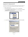
Appendix B: Configuring the PC
In this section, we’ll introduce how to install and configure the TCP/IP correctly in Windows XP.
First make sure your Ethernet Adapter is working, refer to the adapter’s manual if necessary.
1.
Configure TCP/IP component
1)
On the Windows taskbar, click the Start button, and then click Control Panel.
2)
Click the Network and Internet Connections icon, and then click on the Network
Connections tab in the appearing window.
3)
Right click the icon that showed below, select Properties on the prompt page.
Figure B-1
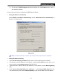
4)
In the prompt page that showed below, double click on the Internet Protocol (TCP/IP).
Figure B-2
- 58 -
AC1200R User’s Guide
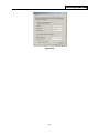
5)
The following TCP/IP Properties window will display and the IP Address tab is open on
this window by default.
Now you have two ways to configure the TCP/IP protocol below:
Setting IP address automatically
Select Obtain an IP address automatically, Choose Obtain DNS server automatically, as
shown in the Figure below:
Figure B-3
Note: For Windows 98 OS or before, the PC and Router may need to be restarted.
Setting IP address manually
1
Select Use the following IP address radio button. And the following items available.
2
If the Router's LAN IP address is 192.168.26.1, specify the IP address as 192.168.2.x (x is
from 2 to 254), and the Subnet mask as 255.255.255.0.
3
Type the Router’s LAN IP address (the default IP is 192.168.26.1) into the Default gateway
field.
4
Select Use the following DNS server addresses. In the Preferred DNS Server field you
can enter the same value as the Default gateway or type the local DNS server IP address.
- 59 -
AC1200R User’s Guide
Figure B-4
- 60 -
AC1200R User’s Guide
Appendix C: Glossary
802.11b - The 802.11b standard specifies a wireless networking at 11 Mbps using
direct-sequence spread-spectrum (DSSS) technology and operating in the unlicensed radio
spectrum at 2.4GHz, and WEP encryption for security. 802.11b networks are also referred to
as Wi-Fi networks.
802.11g - specification for wireless networking at 54 Mbps using direct-sequence
spread-spectrum (DSSS) technology, using OFDM modulation and operating in the
unlicensed radio spectrum at 2.4GHz, and backward compatibility with IEEE 802.11b devices,
and WEP encryption for security.
DDNS (Dynamic Domain Name System) - The capability of assigning a fixed host and domain
name to a dynamic Internet IP Address.
DHCP (Dynamic Host Configuration Protocol) - A protocol that automatically configure the
TCP/IP parameters for the all the PC(s) that are connected to a DHCP server.
DMZ (Demilitarized Zone) - A Demilitarized Zone allows one local host to be exposed to the
Internet for a special-purpose service such as Internet gaming or videoconferencing.
DNS (Domain Name System) – An Internet Service that translates the names of websites into
IP addresses.
Domain Name - A descriptive name for an address or group of addresses on the Internet.
DSL (Digital Subscriber Line) - A technology that allows data to be sent or received over
existing traditional phone lines.
ISP (Internet Service Provider) - A company that provides access to the Internet.
MTU (Maximum Transmission Unit) - The size in bytes of the largest packet that can be
transmitted.
NAT (Network Address Translation) - NAT technology translates IP addresses of a local area
network to a different IP address for the Internet.
PPPoE (Point to Point Protocol over Ethernet) - PPPoE is a protocol for connecting remote
hosts to the Internet over an always-on connection by simulating a dial-up connection.
SSID - A Service Set Identification is a thirty-two character (maximum) alphanumeric key
identifying a wireless local area network. For the wireless devices in a network to
communicate with each other, all devices must be configured with the same SSID. This is
typically the configuration parameter for a wireless PC card. It corresponds to the ESSID in
the wireless Access Point and to the wireless network name.
- 61 -
AC1200R User’s Guide
WEP (Wired Equivalent Privacy) - A data privacy mechanism based on a 64-bit or 128-bit or
152-bit shared key algorithm, as described in the IEEE 802.11 standard.
Wi-Fi - A trade name for the 802.11b wireless networking standard, given by the Wireless
Ethernet Compatibility Alliance (WECA, see http://www.wi-fi.net), an industry standards group
promoting interoperability among 802.11b devices.
WLAN (Wireless Local Area Network) - A group of computers and associated devices
communicate with each other wirelessly, which network serving users are limited in a local
area.
- 62 -