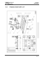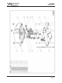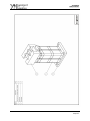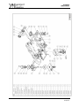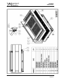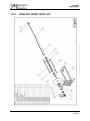
1
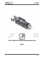
YM 9005/2
USER MANUAL
YM9005/2
TWO STATION THERMOFORMING MACHINE
2013
1/127
YM 9005/2
USER MANUAL
INDEX
1.1 INTRODUCTION
7
1.2 GUARANTEES AND ASSURANCE
9
1.3 TECHNICAL SUPPORT
10
2.1 SAFETY PRECAUTIONS
12
2.2 LABELS AND THE MEANING OF SYMBOLS
14
2.3 WARNINGS
16
3.1 MACHINE TRANSPORT
19
4.1 MACHINE GENERAL INFORMATION
23
4.2 USED EQUIPMENT AND FEEDING PLATE
24
4.3 TECHNICAL SPECIFICATIONS
25
4.4 MACHINE PARTS
26
4.4.1 ROLL-UP AND SUPPLY UNIT (A)
27
4.4.2 CHAIN SYSTEM (B)
28
4.4.3 HEATING UNIT (C)
29
4.4.4 FORMING UNIT (D)
30
4.4.5 STACKING UNIT (F)
31
4.4.6 THE WASTE MATERIAL ROLLING UNIT (H)
32
4.4.7 CONTROL PANEL (I)
33
4.4.8 ELECTRICAL BOARD CABINET (J)
34
4.4.9 AUTOMATIC LUBRICATION UNIT (K)
35
2/127
YM 9005/2
USER MANUAL
4.5 MOULD DIMENSIONS
36
5.1 INSTALLATION AND FIRST START
38
5.1.1 CONTROLLING THE MACHINE BEFORE OPERATING IT
38
5.1.2 THE FEEDING CONNECTIONS
39
5.1.3 THE MOULD CONNECTIONS
40
5.1.4 THE CUTTING EQUIPMENT CONNECTIONS
40
5.1.5 THE MECHANICAL SETTINGS OF THE MACHINE
41
6.1 SCREEN MENU
43
6.1.1 CYCLE
44
6.1.2 HEAT CONTROL
47
6.1.3 CHAIN SERVO SETTINGS
50
6.1.4 FORMING ADJUSTMENT 1
52
6.1.5 FORMING ADJUSTMENT 2
54
6.1.6 CUTTING ADJUSTMENT 1
55
6.1.7 STACKING ADJUSTMENT 1
56
6.1.8 STACKING ADJUSTMENT 2
58
6.1.9 ROBOT ADJUSTMENTS
59
6.1.10 SWEEP ADJUSTMENTS
60
6.1.11 SELECTIONS
61
6.1.12 MANUAL CONTROL
62
6.1.13 STRECHING
63
6.1.14 WORKING PAGE
64
3/127
YM 9005/2
USER MANUAL
6.1.15 USER LEVEL ADJUSTMENT
65
6.1.16 SPEED GRAPH
67
6.1.17 DIGITAL INPUT AND OUTPUT PAGES
68
6.1.18 OTHER ADJUSTMENT 1
69
6.1.19 OTHER ADJUSTMENT 2
70
6.1.20 ALARM PAGE
72
6.1.21 RECIPES
73
6.1.22 RECIPES 2
75
7.1 BEFORE MAINTENANCE
82
7.2 DAILY MAINTENANCE
82
7.3 WEEKLY MAINTENANCE
82
7.4 MONTHLY MAINTENANCE
83
7.5 YEARLY MAINTENANCE
83
7.6 AFTER MAINTENANCE
83
7.7 MAINTENANCE PLAN
84
7.8 CONSUMABLES GIVEN WITH MACHINE
85
8.1 MALFUNCTIONS AND SOLUTIONS
87
9.1 WASTE MATERIAL DISPOSAL
95
10.1 SPARE PARTS AND TECHNICAL SUPPORT PROCEDURE
97
10.2 FORMING SPARE PARTS LIST
98
10.3 STACKING SPARE PARTS LIST
108
10.4 ROBOT STACKING SPARE PARTS LIST
111
4/127
YM 9005/2
USER MANUAL
10.5 STRETCHING SPARE PARTS LIST
115
10.6 CHAIN SPARE PARTS LIST
116
10.7 HEATER HEAT SPARE PARTS LIST
121
10.8 WRAPPER SPARE PARTS LIST
124
10.9 UNWINDER SPARE PARTS LİST
125
5/127
YM 9005/2
USER MANUAL
CHAPTER 1
1. INTRODUCTION
6/127
YM 9005/2
USER MANUAL
1.1 INTRODUCTION
This booklet contains information on how to operate YENIYURT thermoforming
machine,
• regulations on maintenance and operation
• points to consider while transporting and shipping
• warnings on dangerous or harmful conditions on human and nature in use
• information on misuse of the machine,
• introductory and basic information on the machine,
• how to assemble the machine.
Please read and follow the instructions provided in this booklet first to
provide a safe environment for the operators and to keep the machine operating
and keep this booklet permanently.
All the consequences stemming from the operations which are not included
in this booklet will belong to the user.
This booklet includes all the information on Yeniyurt Machine models
mentioned below. The points changing model by model are stated by references
according to the model names, in this booklet:
- Yeniyurt Machine YM 8060 Three Station Thermoforming Machine
- Yeniyurt Machine YM 8060 Four Station Thermoforming Machine
7/127
YM 9005/2
USER MANUAL
PLEASE READ CAREFULLY THIS BOOKLET AND FOLLOW
THE INSTRUCTIONS BEFORE OPERATING THIS MACHINE
THE OPERATORS AND TECHNICAL EMPLOYEES MUST
READ AND UNDERSTAND ALL THE INFORMATION
PROVIDED IN THIS BOOKLET
ALL THE DOCUMENTS RELATED TO THE MACHINE ARE
PROVIDED TO YOU WITH THIS MACHINE, PLEASE READ
ALL
8/127
YM 9005/2
USER MANUAL
1.2 GUARANTEES and ASSURANCE
Yeniyurt Machine, from the sale of the product under warranty during the first
12 months of services. The machine will be the first to install and operate free of
charge by Yeniyurt Machinery. The warranty covers parts of fault conditions and
should be replaced under warranty. Except for services covered by this warranty,
the customer company can not claim any other contract, user errors that may
occur on the machine and the external factor can not claim the cost of other
damaged and can not cancel the sale.
For warranty parts and service changes are made where the machine is
installed according to the technical service personnel and legal laws company
meets the customer the cost of all transportation and accommodation.
As long as the customer uses the company according to the information
specified in the user guide of the machine under warranty service may demand. In
addition, external factors arising from the operator or master shall be charged to
all services not covered by warranty.
In cases of machine malfunction, the user can be solved outside the owner's
manual instructions all the cases, no one other than authorized service Yeniyurt
machine must not interfere with the machine. Otherwise, the results of all actions
arising out of warranty will remain.
9/127
YM 9005/2
USER MANUAL
1.3 TECHNICAL SUPPORT
The order of the technical services will be determined according to the arrival
date and hour of the demands of the service-calling customer firms.
In case of a malfunction, the customer firm must contact with Yeniyurt
Machine via the phone number, fax number or internet by using the information
provided below directly:
Yeniyurt Machinery Industry and Trade Co.
Address: Abdi İpekci Cad. Zorlu Sk. No:10
Bayrampasa Istanbul/TURKEY
Tel: +90 212 565 44 91
Fax: +90 212 613 22 25
web: www.yeniyurt.com
e-mail: [email protected]
10/127
YM 9005/2
USER MANUAL
CHAPTER 2
2. SAFETY
&
ACCIDENT PREVENTATION
11/127
YM 9005/2
USER MANUAL
2.1
SAFETY PRECAUTIONS
1- The machine must not be operated without reading the user guide.
2- Protection and safety parts should not be removed and partially operated.
Otherwise, serious injury or damage can occur.
3- There are safety switches on all doors and gates of the machine and the machine
stops by turning to safety status when any door or gate is open. For safety reasons,
any of these switches should not be cancelled or the machine should not be
operated when any cover or door is open, no matter what the reason is.
4- Because plastic sheets used contain flammable materials and there exist
resistances working with high heat, precautions should be taken against fire. The
machine must be kept near the fire extinguisher.
5- Before pouring any liquid on the machine for extinguishing purpose in case of a
fire threat, all the main circuit must be turned off from the main switch.
Otherwise, an electric shock can occur.
6- Machine lubrication and maintenance operations should not be done while the
machine is operating.
7- A switch is mounted to the machine guards for safety purposes. The guards of
the machine should not be closed for any reasons, when somebody is in the
machine.
8- Before the machine operates, working and technical safety precautions should
be taken and the vicinity of the machine should be controlled.
9- The lubrication and maintenance done after the stop the operation of the
machine, the protectors of the machine must be worn. The machine must not be
12/127
YM 9005/2
USER MANUAL
operated without these protectors. In the area of the operation of the machine,
the warning signs must be followed.
10- The machine in operation must not be intervened with hand or any other
material, with no reason.
11- In case of a breakdown or disruption, people in charge and relevant should be
informed. People without any information or technical training must not interfere
with the machine.
12- While loading sheet coil to the sheet feeding and the pneumatic lifting system
is on, no one must be near the feeding unit apart from the employee controlling
the system.
13- The key must not be left on the emergency stop button which is on the
operating panel of the machine.
14- It is obligatory to build electrical grounding system on the machine.
15- During maintenance, setting or change of mould, the machine must be
suspended by using the emergency stop button on the control panel and the lock on
the emergency stop button must be locked with the key and the key must be kept
only by the person in charge for maintaining, setting or changing the mould.
16- The warning signs on the machine must be given importance to and the written
warnings must be followed. The signs must not be removed or damaged.
17- The room where the machine operates must be lightened and ventilated well
enough for health conditions. When the needed conditions are not supplied, it is
possible to be happen accidents due to loss of attention.
13/127
YM 9005/2
USER MANUAL
2.2
LABELS AND THE MEANING OF SYMBOLS
Warnings could
injury or death.
result
in
serious
Warnings that could result injuries or
could damage the machine parts.
Any intervention must not interfere
with anyone other than authorized
persons when needed.
Automatically moving the machine
while it is running by itself, no one
under the systems should not have.
Automatically moving the machine
while it is running by itself should not
have anyone on the systems.
Systems that automatically moving
the machine while it is running by
itself should not interfere in any way.
High temperatures from the surface
to touch may cause second degree
burns.
Don’t touch rollers while the machine
is running.
Don’t move on the machine while it
is running.
Grounding is not made of static
electricity can build up and static
electricity can cause serious damage
to people with heart disease.
Lubricate not required sections.
14/127
YM 9005/2
USER MANUAL
Automatically when the self-moving
and running gear system should not
intervene.
Pressed on the machine are the parts
may be damaged. Don’t step on these
parts.
There is high-voltage equipment in
the running. Should not interfere
with electrical interruption.
Automatically moving the machine
while the cutter is running. Certainly
should not interfere with the
machine until stopped.
There
is
sharp-edged
track.
Adjustment and maintenance should
be made carefully; otherwise they
can cause deep cuts.
Grounding Warning
Power leakage from the machine could lead to
current leakage that is why grounding should be
done to avoid the danger of electric shock.
Machines, electronic components: a high risk of
damage to the grounding without addition. Gas
pipes, telephone lines or other potential arc can
not be used for earth roads. Improper grounding
can cause electric shock.
15/127
YM 9005/2
USER MANUAL
2.3
WARNINGS
The employees must be out of the area
shown
in
the
photograph
beside,
because a shearing effect is caused
when the covers are closed.
When moulding settings are done on the machine, a threat for chain grabbing
occurs. Due to this, the employees must be kept away and the operator should be
careful during this process.
When the sheet width is adjusted, the
chain demonstrated in the photograph
move. In this case, it can cause damage
16/127
YM 9005/2
USER MANUAL
injuries by grabbing the cloths of the employees or other materials. Thus,
protecting covers of the chains must be removed during adjustment, the employees
must stand away from this area and the one controlling the process should be
completely careful.
When the chain sled engine on the machine
is operating, the gears situated on the
chain as demonstrated in the photograph
can cause damage to the uniforms of the
employees or other materials by grabbing.
Thus, the employees must stand away from
this area and the one controlling the process should be completed carefully.
When the system is operating, the moulding
system forming the product creates a danger for
pulverization. Thus, when the machine is on
process, one must not approach to the system.
When the guards of the machine are opened,
the support column situated in the area
between the two guards becomes dangerous.
Staff must be careful while maintaining the
machine, because it can cause serious injury if
any employee hits his
head.
17/127
YM 9005/2
USER MANUAL
CHAPTER 3
3. INSTALLATION
&
CARRIAGE
18/127
YM 9005/2
USER MANUAL
3.1
MACHINE TRANSPORT
The staff who will be in charge of transport process of the machine must be
informed on the issue of transport and experienced enough to prevent any failure.
Depending on the transport distance and the demands of the customer, the
transport process can be completed through highway or sea way. In the
transportation of highway, all parts are packed properly.
The last users must control the machine when they receive it. All the parts
needing carriage must be carried with suitable equipments according to their
weights and features. Yeniyurt Machine does not accept any damage caused by
improper transportation, transport and untrained staff.
The possible damages caused by any strike of the machine to other objects
can be prevented by putting wooden wedges to suitable places of the machine.
The cargo parts consist of three parts. Machine, electrical cabinet and
feeding unit are packed separately.
Adequate number of trained staff is needed throughout all the stages of
transportation, storing and un-loading.
Lifting points of three station and four station thermoforming machine are
shown at next figures.
19/127
YM 9005/2
USER MANUAL
Two Station Thermoforming Machine Lifting Points:
20/127
YM 9005/2
USER MANUAL
Two Station Thermoforming Machine Layout Plan:
21/127
YM 9005/2
USER MANUAL
CHAPTER 4
4. MACHINE
SPECIFICATIONS
22/127
YM 9005/2
USER MANUAL
4.1
MACHINE GENERAL INFORMATION
All the Yeniyurt Thermoforming Machine models are designed for the
automatic production of disposable plastic food packing and packing for various
sectors. They must not be used for any other purpose. Thermoforming machine
gives the last product by heating, forming, punching, cutting and stacking the
plastic thermoforming material. The technical features of the thermoforming
plastic sheet materials are given in the section of “The Materials to Be Used and
Sheet Feeding”.
The label containing the basic information and serial number is on the sheet
intake facet on the thermoforming machine.
Sample Label of YM9005/2
23/127
YM 9005/2
USER MANUAL
4.2
USED EQUIPMENT AND FEEDING PLATE
Yeniyurt Thermoforming Machine can give the last product only with such
materials PP, PS, Pet, PVC and other suitable materials.
In the case of use of any other material other than stated above, the customer
firm is regarded as not obeying the user instructions. The other materials can be
only used if Yeniyurt Machine tests and confirms them. Sheet feeding unit provides
the intake of the previously stated materials in the roll form. With the help of
sheet feeding unit, the material is transmitted first to the heating station, then
forming/cutting station and finally to the stacking station via chain sled system.
After the stacking station, the last product comes out of the machine and the
waste material waste material is rolled in the wastage rolling unit.
24/127
YM 9005/2
USER MANUAL
4.3
TECHNICAL SPECIFICATIONS
YM9005/2
Tuo Station
Thermoforming Machine
Maximum Mould Size
Maximum Forming
Area
Maximum Cutting
Area
Positive Forming
Height
Negative Forming
Depth
1000x1250mm
960x1210 mm
960x1210 mm
50 mm
80 mm
Maximum Sheet Width
1050 mm
Minimum Sheet Width
600 mm
Upper Heater Heating
Power
Lower Heater Heating
Power
Continuous Power
Consumption
Total İnstalled Power
Vacuum
155 kW
99 kW
130 kW
320kW
205 m³/h
Dry Running Cycle
40 cycle/min
Weight (approx.)
14000 kg
Length
11500 mm
Width
3140 mm
Height
2950 mm
Required Compressor
10 m³/min
Required Cooler
30000 kcal/hour
25/127
YM 9005/2
USER MANUAL
4.4
MACHINE PARTS
Machine mainly consists of these parts: (Figure 4.4.a)
A- Roll Taking-in and Feeding Unit
B- Chain Sled
C- Heating Unit
D- Forming Unit and Cutting Unit
G- Stacking Unit
H- Waste Material Rolling Unit
İ- Control Panel
J- Electric Board Cabinet
K- Automatic Lubrication Unit
26/127
YM 9005/2
USER MANUAL
4.4.1 ROLL-UP and SUPPLY UNIT (A)
The roll taking-in unit functions to load the rolled material to the feeding
unit via two pistols (Picture 4.4.1.a). The process is realized with the button. The
diameter of the material to be loaded to the feeding unit must be maximum
1100mm, minimum 300mm.
27/127
YM 9005/2
USER MANUAL
4.4.2 CHAIN SYSTEM (B)
With the chain sled system, the automatic movement of the sheet is
provided by putting the sheet material automatically to the continuously moving
gears of the chain from two sides. Right before opening of the sheet material from
the roll in the feeding unit is put onto the chain sled, there exists a centering
system at the head of the machine. Via the handle in this system, the width of the
metal sheet is adjusted according to the sheet material and centering is settled in
this way. The cooling water circulates in the chain sled system and the overheating
of the chain is prevented.
28/127
YM 9005/2
USER MANUAL
4.4.3 HEATING UNIT (C)
The sheet material comes to the heating unit via the chain with gears. There
are two pieces of heaters at the opposite sides of each other. These heating units
constitute with infrared ceramic resistances. At the same time, both resistances
have thermocouple resistances to control the heating level. The heating settings of
the heaters can be controlled with the control panel. Both heaters consist of
1000W, 650W and 500W, both thermocouple and non-thermocouple resistances.
The system carrying the heaters is railway system. Via one pneumatic piston,
the heaters are taken into the machine. At the same time, the heating system can
be controlled manually with a handle.
29/127
YM 9005/2
USER MANUAL
4.4.4 FORMING UNIT (D)
Heated sheet that comes from heating oven goes to
forming station by guiding chains. Sheet takes its
first form inside the upper and lower forming blocks
by help of pressured air and/or vacuum. The
movement of forming blocks is obtained with servo
motors that placed at upper and lower side of the
forming station.
30/127
YM 9005/2
USER MANUAL
4.4.5 STACKING UNIT (F)
After the shape is given with the forming station, the product at the cutting
station is not separated from the sheet material totally. The product is cut from
the sheet with slight connection points. The products separated from the sheet
with the pushing force are stacked according to the numbers submitted to the
control panel and the stacked products are put out of the platform.
The stacking unit has two types with options. Though the machine is the
same in total, only the stacking unit can show difference. In the option stacking
from the bottom to the top, the stacking starts from the bottom and come out of
the platform on the top. In the option of stacking from the top to the bottom, the
stacking is done from top to the bottom and the completed product comes out of
the platform at the bottom.
31/127
YM 9005/2
USER MANUAL
4.4.6 THE WASTE MATERIAL ROLLING UNIT (H)
The waste material remaining from the finished product is rolled with the
help of the waste material rolling unit. When the first waste sheet reaches to the
rolling unit, it must be rotated to the waste material rolling shaft manually. At the
same manner, the waste material must be taken from the roll by cutting, when it is
full and the tip of the coming waste material must be rotated manually once more.
For the instructions to eliminate the rolled up material, please read the part
“Waste Material Disposal”.
32/127
YM 9005/2
USER MANUAL
4.4.7 CONTROL PANEL (I)
The control panel is the unit which all the settings and processes are done
with a monitor and the buttons on it (Picture 4.4.9.a). All the processes that will
be done with the monitor and buttons are explained in the part: “The Control
Panel and Operating“
33/127
YM 9005/2
USER MANUAL
4.4.8 ELECTRICAL BOARD CABINET (J)
The electrical board cabinet is the unit to which all the electrical fitting and
control panel is connected and include all the electrical hardware. Moreover, the
electrical board cabinet has fans preventing overheating and dust. These fans need
to be cleaned every 3 months and changed each year.
34/127
YM 9005/2
USER MANUAL
4.4.9 AUTOMATIC LUBRICATION UNIT (K)
The machine contains an automatic lubrication system on its own. With an
oil pump and the lubrication fitting, all the equipments needing lubrication get
lubricated.
35/127
YM 9005/2
USER MANUAL
4.5
MOULD DIMENSIONS
36/127
YM 9005/2
USER MANUAL
CHAPTER 5
5. FIRST START AND
SETTINGS
37/127
YM 9005/2
USER MANUAL
5.1
INSTALLATION AND FIRST START
5.1.1 CONTROLLING THE MACHINE BEFORE OPERATING IT
Before operating the machine, it is obligatory to do some controlling:
* Control each connection in terms of regularity and that the protective equipment
is closed.
* Control the pneumatic connections.
* Control the adequacy of the air pressure linked to the machine. (6 bar)
* Check the cooling system connections.
* Check the amount of the cooler liquid.
* Check all the surfaces needing lubrication.
* Check if the power supply is fully seated to the electrical panel.
* Check if the input voltage is sufficient.
Important: If all the engines operate backwards, replace the phases of the power
supply in opposite. Before doing this, be sure that you cut all the electrical
connections.
* Check all the emergency buttons. All the buttons are red and marked with yellow
rings.
* Check all the door and moving system switches. The machine is supposed to stop
operating when any guard is open.
* Check the emergency lights and alarm. They are supposed to operate in case of
an alarm.
* Check the heat detectors before turning them on (room temperature) by using
the control panel. Later, check if the heating level increases when the machine is
on.
* Finally, check all the systems if they operate in manual mode.
38/127
YM 9005/2
USER MANUAL
5.1.2 THE FEEDING CONNECTIONS
The power supply connections must be done according to the law and
regulations of the country where the machine will operate.
The pneumatic connections can be done via the use of 1” hose for the parts
demonstrated in the pictures. Depending on the demand of the customers, a turn
on-off valve can be put to the machine.
On the thermoforming machine, there is water input and output connections
at location demonstrated on the next picture. The input and output of the water
must be set correctly.
39/127
YM 9005/2
USER MANUAL
5.1.3 THE MOULD CONNECTIONS
The dimensions and connections of the machine must be compatible with the
size and connection standards. Control the technical features of the machine. The
entire moulds that are done by others manufacturers according to the demands of
the customer must also compatible with these features.
The mould connections must be completed by the staff expert on the issue
and with sufficiency to follow the technical procedures.
5.1.4 THE CUTTING EQUIPMENT CONNECTIONS
To connect the cutting equipment, the control buttons and cutting blocks
must be turned on manually, right before the heating resistance is on. According to
the first cuttings, the height of the cutting plaques must be tuned fine to cut the
material.
40/127
YM 9005/2
USER MANUAL
5.1.5 THE MECHANICAL SETTINGS OF THE MACHINE
Some mechanical settings need to be done before the operation of the
machine. These settings are done according to the materials and moulds used.
Standard settings are here: The width setting of the chain sleds according to the
width of the material to be used. During the adjustments, one should pay attention
to the chain sled forming unit, the cutting unit or the stacking unit and not to hit
the equipments.
41/127
YM 9005/2
USER MANUAL
CHAPTER 6
6. CONTROL PANEL &
WORKING
42/127
YM 9005/2
USER MANUAL
6.1
SCREEN MENU
The touch screen is the main screen containing all the menus. To operate the
machine, all the required settings and data can be accessed through the menus on
this screen.
There are several settings screen on the main menu. These are;
Cycle, Heat Control, Lower Zone Temperature, Cutting and Other
Adjustments, Chain Servo Settings, Forming Adjustment, Cutting Adjustment,
Stacking Adjustments, Sweep Adjustments, Punching Adjustments, Manuel Control,
Streching, Working Page, User Level Adjustments, Speed Graph, Digital Input and
Output, Other Adjustment, Driver Ramp Adjustments, Selections, Alarms and
Receipe.
Pages that have a button at up-right corner means that there is an another
setting page next. And pages that have a button at up-left corner means that you
can go previous page by pressing on it.
On touching the place with changeable data, a keyboard and a numerator
come to the screen. Some input boxes demonstrate the data that can change and
some other input boxes demonstrate the data that can be changed only by the staff
of the authorized service.
43/127
YM 9005/2
USER MANUAL
6.1.1 CYCLE
On this page, working periods of some parts of the machine can be set. Also the
cycle time can be seen here.
P/S: Values can be given on parts with white background
Cycle Time
The first box from the two boxes near cycle time is for cycling time. The second
box is for the completed cycle time. The cycle time is the time spent for forming,
cutting and stacking. In the first box, this value can be submitted as “second”.
Chain
Start and duration values on the line of “chain” provide information deciding on
when the chain system starts and finishes during the cycle time.
44/127
YM 9005/2
USER MANUAL
Form Air
Here the forming air starting and duration times can be changed. The ON/OFF
indicator on the rightmost of the line demonstrate whether the air valve is on or
off at that time.
Vacuum
These values control the vacuum air system starting and duration times. The
ON/OFF indicator on the rightmost of the line demonstrate whether the air vacuum
is on or off at that time.
Eject Air
These values control the eject air system starting and duration times. The ON/OFF
indicator on the rightmost of the line demonstrate whether the eject air is on or
off at that time.
Upper Plug Assist
These values control the upper plug asist system starting and duration times in the
cycle. The ON/OFF indicator on the rightmost of the line demonstrate whether the
upper plug assist is on or off at that time.
Upper Forming
These values determine when the upper forming unit starts to closing and opening
in the cycle movement of the machine. Time column demonstrates the current
time of related movement part of the machine. It goes downward at closing time
and goes upward at opening time.
Upper Cutting
These values determine when the upper cutting unit starts to closing and opening
in the cycle movement of the machine. Time column demonstrates the current
time of related movement part of the machine. It goes downward at closing time
and goes upward at opening time.
Lower Forming
These values determine when the lower forming unit starts to closing and opening
in the cycle movement of the machine. Time column demonstrates the current
45/127
YM 9005/2
USER MANUAL
time of related movement part of the machine. It goes upward at closing time and
goes downward at opening time.
Lower Cutting
These values determine when the lower cutting unit starts to closing and opening
in the cycle movement of the machine. Time column demonstrates the current
time of related movement part of the machine. It goes upward at closing time and
goes downward at opening time.
Stacking
These values determine when the stacker unit starts movement in the cycle
movement of the machine. Time column demonstrates the current time of related
movement part of the machine.
Lower Punching
These values determine when the lower punching unit starts to closing and opening
in the cycle movement of the machine. Time column demonstrates the current
time of related movement part of the machine. It goes upward at closing time and
goes downward at opening time.
Upper Punching
These values determine when the upper punching unit starts to closing and opening
in the cycle movement of the machine. Time column demonstrates the current
time of related movement part of the machine. It goes downward at closing time
and goes upward at opening time.
Form Air Pressure
Here forming air pressure value can be set as bar unit.
Pressing this button makes the cycle time is changed option automatic opening
and closing times
46/127
YM 9005/2
USER MANUAL
6.1.2 HEAT CONTROL
This panel demonstrates all the heating values of the areas with a
temperature. All the heating columns and rows can be configured one by one.
All zones temperatures can be set by SET values one by one. The actual
degrees of zones can be seen from ACT value boxes. All temperatures can be offset
from OFFSET value box and all temperatures can be tolerated.
Upper heater has14 vertical and 12 horizontal zone. ON/OFF buttons on
stage 1 and stage 2 area are used to activate and deactivate 1.12. and 2.11. zone
heater when using narrow moulds.
The maximum temperature of the oven depending on the processed product
can be entered in the Max Temperature section by the technician.
47/127
YM 9005/2
USER MANUAL
Lower zone heater has 3 horizontal sections which 1.2.3. are first,
4.5.6.7.8.9 are second and 10.11.12. are third heater zone. Lower heater totally
has 3 heater zone.
48/127
YM 9005/2
USER MANUAL
values appear in this section of the upper and lower heating elements. red line shows
the pitch of the mold
49/127
YM 9005/2
USER MANUAL
6.1.3 CHAIN SERVO SETTINGS
When the chain backward button is pushed, the chain system goes back manually.
Likewise, the chain system goes forth if the chain forward button is pushed.
With chain length forward button, the chain system moves one step forth.
The value on Manual Speed (mm/s) is the velocity value of the chain system when it moves
manually.
The value on Automatic Speed (mm/s) is the velocity value of the chain system when
it moves automatically.
The value on Chain Step Length (mm) is the value of the chain system how much it
moves when it moves.
50/127
YM 9005/2
USER MANUAL
The value on Backward Length (mm) is the value of the chain moving length when it
moves one step back ward. This section serves to reduce the failures caused by gaps in the
chain system in the course of years of usage. Yeniyurt service is needed.
The value onChain Backward Speed (mm/s), in this section Backward Length, engine
speed is to be entered.
Acceleration Time (s) determines the acceleration value of the chain when it moves.
Deceleration Time (s) determines the deceleration value of the chain sytsem when it
is slowing and stopping.
P.V. (mm) value shows the actual position of the chain system.
Mould Width(mm) In this section the mould width is to be entered.
P/S: The technician has Access to this page.
51/127
YM 9005/2
USER MANUAL
6.1.4 FORMING ADJUSTMENT 1
When dotted square button pushed, lower/upper forming system moves to
its origin position.
MIN and MAX input boxes are determine the minimum and maximum levels of
lower/upper forming press.
“PV (mm)” parts demonstrate the existing value of upper and lower forming
press.
By “Manual” up and down arrow buttons, related unit movements can be
operated with up and down buttons manually.
“Manuel Vel (%)” values determine the speed of lower/upper forming press
while moving by manual buttons.
52/127
YM 9005/2
USER MANUAL
“Opening Vel (%)” values determine the opening speed of lower/upper
forming press and “Closing Vel (%) determines the closing speed of lower/upper
forming press.
The value that entered to “Start Distance (mm)” input box determines the
starting distance position of lower/upper forming press.
“Opening Acc (s)” values determine the acceleration of the lower/upper
forming press by unit of seconds and “Closing Acc (s)” values determine the
acceleration of the lower/upper forming press by unit of seconds.
“Opening Dec (s)” values determine the deceleration of the lower/upper
forming press by unit of seconds and “Closing Dec (s)” values determine the
deceleration of the lower/upper forming press by unit of seconds.
“Closing Step Speed (%)” value determine the steps as percentage while
lower/upper forming press systems are closing.
“Closing Step Pos Length” value determine the steps as length while
lower/upper forming press systems are closing.
“Step Speed” on/off button selects the step speed action is on or off.
Form Distance When the value to be written in this section post in this
section begins forming the air before the cut-off value will make the form and the
form must be set to miss the weather, for example (0) be written
53/127
YM 9005/2
USER MANUAL
6.1.5 FORMING ADJUSTMENT 2
Pv pozizyonunu shows snapshots of the mold
pozizyonu mold removal is determined with the help of the up and down
buttons, the value is written to the following section of the liquid to the next by
pressing the button changes the upper and lower molds mold removal position is
automatically
“Form Lock”,.There are buttons at the bottom of the page for lower and
upper forming moulds that activates and de-activates the related unit such as
Mold Position Pressing this button on the right side is sent to the setpoint
54/127
YM 9005/2
USER MANUAL
6.1.6 CUTTING ADJUSTMENT 1
When pushed the green arrowed button while pressing auxiliary button from
control panel, cutting height servo motor goes to its origin position.
“SV (mm)” areas can be set by operator to determine cutting height and
cutting station position manually.
“PV (mm)” parts demonstrate the existing value of cutting height and
cutting station position.
By “Manual” up/down and forward/backward arrow buttons, related unit
movements can be operated with up and down buttons manually.
“Chain Length Forward” button used to forward chain system one step
forward.
55/127
YM 9005/2
USER MANUAL
6.1.7 STACKING ADJUSTMENT 1
Square button positions the lower plucking system to origin.
Left half of page is for sweeping settings. “Start Quantity” determines that
when sweep system first works after first products stacked.
“Stacker Count SV” input value box determines the count of total product
that stakced before sweeping system is active. And “Stacker Count PV” shows the
actual stacked material on stacking roof.
Reset button labeled with “0->”, resets the stacking system count number.
“Second Position” button moves the stacking system to second level position
manually and “First Position” button moves the system to first level. Also “Start
Position” button moves the stacking sytem to it’s initial position.
56/127
YM 9005/2
USER MANUAL
“Manual Up” and “Manual Down” buttons move the stacking sytsem to up
and down manually. “Actual Position” value box indicates the actual system
position.
The half right page area labeled “Stacking Station” includes settings about
stacking station.
“SV” box value the stacking station position to move determines the system.
“PV (mm)” box shows the actual position of the stacking station.
“Left” and “Right” arrow buttons move the station to backward and
forward. The buton with labeled twin arrow moves the chain to one step forward
“Open Waiting time (s)” keeps the upper and lower forming blocks waiting
as long as the time entered in this section.
“Chain Length Forward”pressing button used to forward chain system one
step forward by pressing auxiliary button
The buttons at “SWEEPER 1” area are used to move the sweeper 1 to
forward and backward one step and the second set of forward backward buttons
are used to move the sytem manually while pressed.
57/127
YM 9005/2
USER MANUAL
6.1.8 STACKING ADJUSTMENT 2
“Up Speed Change” and “Down Speed Change” ON/OFF buttons activate and deactivate
the speed change of up/down stacking system.
“Step up position” determines the position of stacking system when step system is at up.
“Step up speed” determines the speed of the stacking system’s step property.
“Manual Vel (%)” value determines the speed of stacking system when it’s controlled
manually.
“UP ACC(s)” and “DOWN ACC(s)” values determine the acceleration of stacking system
when its going to upward/downward.
“UP DEC(s)” and “DOWN DEC(s)” values determine the deceleration of Stacking system
when its going to upward/downward
Robot and Stacker allows the robot to move that unit and sorting unit at the same
time
Robot State type setting unit ensures that the center of the robot unit
58/127
YM 9005/2
USER MANUAL
6.1.9 ROBOT ADJUSTMENTS
horizontal and vertical distances and velocities of the robot is set to move the robot vacuum
system valves are provided on the selection of valves and ABC
59/127
YM 9005/2
USER MANUAL
6.1.10 SWEEP ADJUSTMENTS
Sweeping adjustments for stacked products on the stacking roof can be set
on this page.
“Sweeping speed referance (Hz)” and “Wrapper Required Tension (kg)”
values can be set by related input boxes.
“Wrapper Required Tension (kg)” value adjusts the tension required for the
wrapper system.
60/127
YM 9005/2
USER MANUAL
6.1.11 SELECTIONS
RobotAB Stacking AB When it Works
Open Vacuum on Automatic When it Works
Thermoregulator Aktive When it Works
Stacking Constant Positon for robot rises up to the bottom step is selected in
the same way marshaling step robot is high
İmposition With robot When it Works
İmposition bottom When it Works
61/127
YM 9005/2
USER MANUAL
6.1.12 MANUAL CONTROL
All buttons on this “Manual Control” page are used to move the labeled
system by manually and selection to on or off.
Upper plug assist up and down button are move the plug asist to up and
down by manually.
Heater1-2 backward and forward arrow buttons are moves the heater system
to inside and outside of machine.
“Form Air Valf”, “Vacuum”, “Eject Air”, “WastageWinder”, “Lubrication”
and “Water Valve” on/off buttons are activate and deactivate the related systems.
62/127
YM 9005/2
USER MANUAL
6.1.13 STRECHING
There are “Input Tension”, “Middle 1 Tension”, and “Output Tension” sector
stretch settings for chain can be adjusted on this page.
“Offset” value input box for all these sectors to offset actual values.
“PV (mm)” boxes demonstrate the actual position of all stretch sectors.
When dotted square button pushed, all stretch sectors move to their origin
position.
When dotted square button pushed, stretching system moves to its origin
position.
“
” is Set value button. It sets to the value entered in SV section.
Mould Width(mm) Mould width is to be entered in this section.
63/127
YM 9005/2
USER MANUAL
6.1.14 WORKING PAGE
Home set positions can be set on this page and actual positions of stations
demonstrated by “PV (mm)” value boxes.
When dotted square button pushed, all stations and system move to their
origin position.
Upper/lower forming, cutting and punching station home positions can be
set one by one.
Machine lighting makes the ligthing inside the machine active or passive.
64/127
YM 9005/2
USER MANUAL
6.1.15 USER LEVEL ADJUSTMENT
User level and control panel language settings are on this page. You can
choose the language you prefer by pressing on it.
Also a password protection system is included to system for using by Yeniyurt
Machine technicians. These password protected setting areas are need to be
change only by Yeniyurt techinicians. Otherwise, these settings can be cause
injuiry of personel or damage the machine systems.
65/127
YM 9005/2
USER MANUAL
66/127
YM 9005/2
USER MANUAL
6.1.16 SPEED GRAPH
Speed Graph page shows the graphical values of chain, upper cutting, upper
form and stacking systems.
67/127
YM 9005/2
USER MANUAL
6.1.17 DIGITAL INPUT AND OUTPUT PAGES
Digital output pages are used to control all systems and sensors if they are
working or not.
When green light indicates at the the end of rows, that means the system
written on this row is working true at the moment.
You or Yeniyurt Machine techinicans can check the system parts by these
pages.
68/127
YM 9005/2
USER MANUAL
6.1.18 OTHER ADJUSTMENT 1
“Lubrication Start Press Quantity” value determines the start action time of
lubrication system. When count completed in this value box, the lubrication system
starts to pump oil to the system.
“Lubrication Process Quantity (Piston Stroke Quantity)” value input box
determines the count of lubrication.
“Manuel Lubrication Processing Time(s)” value determines the lubrication
duration while it’s controlling by manuel.
“Chain Lubrication Start Press Quantity” value determines the start action
time of lubrication system. When count completed in this value box, the
lubrication system starts to pump oil to the system.
69/127
YM 9005/2
USER MANUAL
6.1.19 OTHER ADJUSTMENT 2
“Form Analog Referance (bar)” value determines the referance of form
analog.
“Unwinder Speed Referance (bar)” value adjusts the referance speed of
unwinder system.
“Station Motor Speed Referance (Hz)” value determines all station’s
movement servo motor’s referance speed.
“Upper Cutting Motor Speed Referance (Hz)” value determines the up
cutting block’s movement servo motor’s speed referance.
“Wrapper Required Tension (kg)” value adjusts the tension required for the
wrapper system.
70/127
YM 9005/2
USER MANUAL
“Conveyor Speed Referance (Hz)” value sets the movement speed referance
of the conveyor system.
“Form of Passing an Empty Quantity” determines the empty quantity pass
from forming station for each.
Date and time settings are on this page. After input for all date and time
values, “Set Time” button have to be pressed to adjust the current date and time.
71/127
YM 9005/2
USER MANUAL
6.1.20 ALARM PAGE
All current and previously alarms and malfunctions that given by the
machine can be seen on this page.
72/127
YM 9005/2
USER MANUAL
6.1.21 RECIPES
Each mould has its own settings. When the mould’s settings are changed,
must be redone. In order to deal with this situation and save all the settings, a
page named recipe is constructed.
All the settings of a mould adjusted before can be saved with a given name
and these settings can be re-uploaded to the memory when needed.
When the same mould is required, the pre-set adjustments are recalled
easily.
Active product recorded settings can be seen by title “Active Product”.
The list on the left of page includes previously recorded settings for each
product.
73/127
YM 9005/2
USER MANUAL
“Product List” 400 recipes can be saved.
“Select Product” Product List, the mould to be run must be selected and
carried to Active product section by pressing Select Product button.
“Load” by pressing mould Load button, the loading process is accomplished,
when the square field on the lower left side of the screen is green.
“Save As” to change the actual values of the product’s recipe. It can be
used to create another recipe for another product by chaning the product name
and enter the Yes button. The steps must be done respectively.
“Delete” the unnecessary product recipes will be deleted.
74/127
YM 9005/2
USER MANUAL
6.1.22 RECIPES 2
Recipe Copy, to copy recipes from the machine to USB or from USB to
machine. The list on the left side of the screen shows the list of the recipes in the
machine, and on the right side of the screen shows the list of the recipes in the
USB. The recipes can be carried by pressing the button in the middle of the screen.
75/127
YM 9005/2
USER MANUAL
6.2
OPERATOR PANEL
This chapter includes the buttons under the digital screen of the control
panel with their explanations.
76/127
YM 9005/2
USER MANUAL
6.21.1 Manual - Auto (1)
When pushed once, the light is on and the machine turns into automatical settings.
When pushed once more, the light turns off and it turns into manual settings. If the start
button is not pushed within 15 seconds after switching the authomatic settings, it turns back
into manual mode again.
6.21.2 Stop (2)
When pushed, the machine stops.
6.21.3 Start (3)
When pushed, the machine starts operating.
6.21.4 Chain (4)
When pushed, the chain system starts operating.
6.21.5 Forming (5)
When pushed, the forming station starts operating.
6.21.6 Cutting (6)
When pushed, the cutting station starts operating automatically.
6.21.7 Stacking (7)
When pushed, the stacking station starts operating automatically.
6.21.8 Buzzer (8)
This is the mechanism of the alarm sound.
6.21.9 Auxiliary Button (9)
If the stations are required to be moved manually, then the necessary manual
movement button should be pushed while keeping this button pressed.
6.21.10 Emg. Plc Alarm Reset Button (10)
It resets the alarms to let the system operate. Just one push is enough.
6.21.11 Alarm Lamp (11)
It warns with a light in case of an emergency situation.
6.21.12 Chain Backward (12)
It checks the servo motor on the chain sled. It lets the chain move from the direction
of scrap winding part to the direction of foil feeding part. When the button is pushed, the
movement will continue without any stop. It does not work during the process of automatic
settings.
6.21.13 Chain Forward (13)
77/127
YM 9005/2
USER MANUAL
It checks the servo motor on the chain sled. It lets the chain move from the direction
of foil feeding part to the direction of scrap winding. The movement will continue without
any stop. It does not work during the process of automatic settings.
6.21.14 Emergency Stop (14)
In case of a breakdown or error, this button ends the current process immediately.
The machine stops operating no matter what it is doing. To cancel the emergency, it is
enough to push the button and then rotate it in the arrow direction. As it may cause damage
to the machine in heavy use, it should be used only in case of an emergency.
6.21.15 Form Top Up (15)
It provides the upward movement of the forming station. When pushed, the
movement continues. Only operates in manual setting.
6.21.16 Form Top Down (16)
It provides the downward movement of the forming station. When pushed, the
movement continues. Only operates in manual setting.
6.21.17 Form Below Up (17)
It provides the upward movement of the lower forming station. When pushed, the
movement continues. Only operates in manual setting.
6.21.18 Form Below Down (18)
It provides the downward movement of the upper forming station. When pushed,
the movement continues. Only operates in manual setting.
78/127
YM 9005/2
USER MANUAL
Unwinder Control Buttons
The first button has two levels. While this switch is at left position, unwinder works
only at auto-working. If the switch is at right (second) position, the unwinder works
continuously. The second button is an emergency stop button that stops the whole
machine at an emergency situation.
Chain Control Buttons
First button moves the chain to forward continuously while
pushed down. Second button moves the chain to backward
continuously while pushed down. The third button is an
emergency stop button that stops the whole machine at an
emergency situation
79/127
YM 9005/2
USER MANUAL
Feeder Control Buttons
First
button
turns
the
sheet
feeder
continuously while been pushed down. Second
button is an emergency stop button that stops
the whole machine at an emergency situation.
Third handle used for replacing sheet roll with
a new one. While handle is at first position, it
moves sheet feeder down with pneumatic
pistons. While handle is at second position, it
moves sheet feeder up with pneumatic pistons.
80/127
YM 9005/2
USER MANUAL
CHAPTER 7
7. MAINTENANCE
81/127
YM 9005/2
USER MANUAL
7.1
BEFORE MAINTENANCE
Before maintenance and repair operations in the machine, the machine must
be stopped and energy disconnection completely must be assured. The Emergency
stop button must be switched on during the maintenance operation and the lockkey must be carried by the responsible staff for the maintenance.
7.2
DAILY MAINTENANCE
Eccentric sleeve bearings, chain guides and moving block bush are lubricated
automatically with central lubrication system (Daily Maintenance for machines
without automatic lubrication system).
7.3
WEEKLY MAINTENANCE
1) The casting arms on the cam block of the machine must be checked optically
weekly. In case of determining appropriateness, the machine shall not be run and
precautions must be activated according to the manual – hand book of the
machine.
2) General cleaning of the machine must be done minimum weekly. Dusty zones of
the machine must be cleaned with blowgun.
3) The air filters of the fan in the electrical cabinet must be cleaned with airblowgun on weekly basis. The filters not cleaned regularly are chocked; the air
circulation will be reduced causing parts damage due to overheating.
4) There will be water logging (water accumulation) in the air tanks on the top of
the machine. The water in the air tank has to be removed once a week to utilize
the air tank with maximum efficiency.
82/127
YM 9005/2
USER MANUAL
7.4
MONTHLY MAINTENANCE
1) After a month of running the machine, the pneumatic systems have to be
checked. Any possible air leakage on the pistons must be checked. Pneumatic
valves must be checked for their functionality. The level of the conditioning
lubricant must be checked. Lubricant must be added in case of any reduction under
level.
2) Electrical installations must be checked once a month by qualified specialists.
Motors have to be checked against overheating. Moving part sensors and magnetic
sensors of the pistons must be checked.
7.5
YEARLY MAINTENANCE
1) Annual maintenance will be done by Yeniyurt service team. The machine will be
checked for all parts and its optimum efficient functionality. Any damaged and
worn parts are to be replaced.
2) Ventilation filters in the electrical cabinet must be changed once a year.
Otherwise electronic parts (products) can be damaged.
7.6
AFTER MAINTENANCE
Please do not forget any loose or not belonging parts in the unit after the
maintenance process is finished.
83/127
YM 9005/2
USER MANUAL
7.7
MAINTENANCE PLAN
Period
Every Day
Every Two Days
Every Week
Every Week
Every Week
Every Week
Every Week
Every Month
To Do
Consumables
General check of moving parts
for stability and the whole
machine must be done.
Eccentric sleeve bearings, chain
guides and moving block bushes
must be lubricated every two
weeks. (In automatically
lubricated machines, this
process done by automatic
lubrication system)
The casting arms on the cam
block must be checked for
stability.
General cleaning of the
machine must be done and
dusty zones of the machine
must be cleared with blowgun.
Ventilation filters on electric
cabinet must be cleared with
air.
There will be water logging
(water accumulation) in the
air tanks on the top of the
machine. This accumulation
hast to be removed to
utilize the air tank with
maximum efficiency.
Lubricant level from indicator
of vacuum pump must be check
and in case of low lubricant
indicate, lubricant addition
must be done.
Pneumatic systems have to
be checked. Any possible
air leakage on pistons and
functionality of pneumatic
valves must be checked.
Lubricant must be added in
case of any reduction of
conditioning lubricant level.
-
-
-
-
Shell Vitrea 100
Circulation
Lubricant
Conditioning
Lubricant
84/127
YM 9005/2
USER MANUAL
Every Month
Electrical installations must
be checked by qualified
specialists. Motors have to
be checked against
overheating. Moving part
sensors and magnetic
sensors of the pistons must
be checked.
Every Month
Vacuum tank have to be
checked for its functionality.
Vacuum fitler must be cleared
and lubricant level has to be
checked. In case of any low
level lubricant, lubricant
addition must be done.
-
Shell Vitrea 100
Circulation
Lubricant
Every Year
Ventilation filters on the
electric cabinet have to be
replaced with new ones.
Otherwise electric parts
(products) can be damaged
(overheating, short circuit,
etc.)
-
Every Year
Any moving parts and the
whole machine have to be
checked for functionality
and optimum efficiency by
Yeniyurt service team. Any
damaged and worn parts
have to be replaced.
-
7.8
CONSUMABLES GIVEN WITH MACHINE
o Mini Relay (2 pieces)
o M12 Proximity Sensor (2 pieces)
o M8 Proximity Sensor (2 pieces)
o Magnetic Piston Sensor (2 pieces)
o 40A Fuse (2 pieces)
o Tools Kit
85/127
YM 9005/2
USER MANUAL
CHAPTER 8
8. TROUBLESHOOTING
86/127
YM 9005/2
USER MANUAL
8.1
MALFUNCTIONS AND SOLUTIONS
The list of any possible breakdowns is given in a chart below. Each
malfunction, reason and solution is explained. When a malfunction occurs, it should
be searched in this list for a solution. If the stated solution does not function, then
you should contact with the firm.
MALFUNCTION
The alarm window alarms
that “ The Emergency
Stop is Pressed”
The alarm window
indicates “The Heating
Oven Cannot Continue”
The alarm window
indicates “The Bumper
Cannot Go Up”
REASON
SOLUTION
If the machine is ready to
operate, the pressed
One or more emergency
emergency stop buttons
stop buttons are pressed
are pushed. If none of the
or because emergency
buttons are pressed, a
stop button circuit is in
short circuit or
series, a short circuit or
disconnection might have
disconnection occur.
occured. Contact with the
firm.
Check the pressure of the
The heating oven in the
air coming into the
machine cannot move
machine. The oven should
forth. The pistol providing
be controlled if got
this movement or the
stuck. The moving pan is
limit switch can be
moved manually by
malfunctioning. Or the
using the menu on the
oven might be jammed.
control panel – manuel
Also, the valve of the
settings and via the leds
pistol providing the
the sensors are
movement can be out of
controlled if they are
order or the pressure of
operating properly. If the
the air coming to the
problem is not solved,
machine is not sufficient.
contact with the firm.
The upper forming station Check the pressure of the
might be jammed. There
air coming into the
might not be enough air
machine. The upper
pressure in the machine.
forming station might be
The bumper pistol or
disassembled to see if
pistol
there is any jam. The led
limit switch can be out of buttons can be checked if
order. The bumper
they are on/off. The
encoder
bumper encoder values
value might be entered
should be checked. If
wrong. The buffer might
the problem is not solved,
87/127
YM 9005/2
USER MANUAL
The alarm window
indicates “The Bumper
Cannot Go Down”
The alarm window
indicates “The Lower
Stacking 1. Stage Cannot
Go Up”
The alarm window
indicates “The Lower
Stacking 1. Stage Cannot
Go Down”
The alarm window
indicates “The Lower
Stacking 2. Stage Cannot
Go Up”
The alarm window
indicates “The Lower
Stacking 2. Stage Cannot
Go Down”
not be chosen from the
options page.
The lower forming station
might be jammed. There
might not be enough air
pressure in the machine.
The bumper pistol or
pistol
limit switch can be out of
order. The bumper
encoder
value might be entered
wrong. The buffer might
not be chosen from the
options page.
The stacking station might
be jammed. There might
not be enough air
pressure
in the machine. The
bumper pistol or pistol
limit
switch can be out of
order.
The stacking station might
be jammed. There might
not be enough air
pressure
in the machine. The
bumper pistol or pistol
limit
switch can be out of
order.
The stacking station might
be jammed. There might
not be enough air
pressure
in the machine. The
bumper pistol or pistol
limit
switch can be out of
order.
The stacking station might
be jammed. There might
not be enough air
pressure
in the machine. The
contact with the
firm.
Check the pressure of the
air coming into the
machine. The lower
forming station might be
disassembled to see if
there is any jam. The led
buttons can be checked if
they are on/off. The
bumper encoder values
should be checked. If
the problem is not solved,
contact with the
firm.
Check the pressure of the
air coming into the
machine. The stacking
encoder values should
be checked. If the
problem is not solved,
contact with the firm.
Check the pressure of the
air coming into the
machine. The stacking
encoder values should
be checked. If the
problem is not solved,
contact with the firm.
Check the pressure of the
air coming into the
machine. The stacking
encoder values should
be checked. If the
problem is not solved,
contact with the firm.
Check the pressure of the
air coming into the
machine. The stacking
encoder values should
be checked. If the
88/127
YM 9005/2
USER MANUAL
The alarm window
indicates “The Upper
Stacking Stage Cannot Go
Up”
The alarm window
indicates “The Upper
Stacking Stage Cannot Go
Down”
The alarm window
indicates “The Sweeper
Cannot Go Forward”
The alarm window
indicates “The Sweeper
Cannot Go Backward”
The alarm window
indicates “The Servo
Motor Malfunction”
The alarm window
bumper pistol or pistol
limit
switch can be out of
order.
The stacking station might
be jammed. There might
not be enough air
pressure
in the machine. The
bumper pistol or pistol
limit
switch can be out of
order.
The stacking station might
be jammed. There might
not be enough air
pressure
in the machine. The
bumper pistol or pistol
limit
switch can be out of
order.
The stacking station might
be jammed. There might
not be enough air
pressure
in the machine. The
bumper pistol or pistol
limit
switch can be out of
order.
The stacking station might
be jammed. There might
not be enough air
pressure
in the machine. The
bumper pistol or pistol
limit
switch can be out of
order.
The servo motor driver
might be out of order.
There might be an
electrical
or mechanical
malfunction.
There might be a short
problem is not solved,
contact with the firm.
Check the pressure of the
air coming into the
machine. The stacking
encoder values should
be checked. If the
problem is not solved,
contact with the firm.
Check the pressure of the
air coming into the
machine. The stacking
encoder values should
be checked. If the
problem is not solved,
contact with the firm.
Check the pressure of the
air coming into the
machine. If the problem is
not solved, contact
with the firm.
Check the pressure of the
air coming into the
machine. If the problem is
not solved, contact
with the firm.
By controlling the
malfunction status, the
technical service should
be called.
The vacuum motor
89/127
YM 9005/2
USER MANUAL
indicates “The Vacuum
Motor Thermic
Malfunction”
The alarm window
indicates “The Scrap
Winding Motor
Malfunction”
The alarm window
indicates “The Upper
Forming Motor
Malfunction ”
The alarm window
indicates “The Lower
Forming Motor
Malfunction ”
The alarm window
indicates “The Upper
Cutting Motor
Malfunction ”
The alarm window
indicates “The Lower
Cutting Motor
Malfunction ”
The alarm window
indicates “The Chain
Servo Motor
Malfunction”
The alarm window
indicates “1. Front Cover
Switch”
The alarm window
indicates “2. Front Cover
Switch”
circuit or over current in
the vacuum motor or
there
might be a mechanical
problem.
There might be a
malfunction in the scrap
winding motor. There
might be a mechanical or
electronic problem.
There might be a
malfunction in the motor.
There might be a
mechanical or electronic
problem.
There might be a
malfunction in the motor.
There might be a
mechanical or electronic
problem.
There might be a
malfunction in the motor.
There might be a
mechanical or electronic
problem.
There might be a
malfunction in the motor.
There might be a
mechanical or electronic
problem.
There might be a
malfunction in the motor
driver. There might be a
mechanical or electronic
problem in servo.
thermic driver in the
electrical panel should be
checked and the
technical service should
be called.
The scrap winding motor
driver in the electrical
panel should be checked
and the technical
service should be called.
The upper motor driver in
the electrical panel
should be checked and
the technical service
should be called.
The lower motor driver in
the electrical panel
should be checked and
the technical service
should be called.
The upper motor driver in
the electrical panel
should be checked and
the technical service
should be called.
The upper motor driver in
the electrical panel
should be checked and
the technical service
should be called.
The servo motor driver in
the electrical panel
should be checked and
the technical service
should be called.
Check if the 1st front
1. front cover switch is
cover is closed. If is not
not
closed, close it. If the
detected. The cover is
problem continues, the
not
switch might be out of
closed or the switch is not order or the cables are
functioning properly.
damaged. Please contact
with the firm.
2. front cover switch is
Check if the 2nd front
not
cover is closed. If is not
detected. The cover is
closed, close it. If the
not
problem continues, the
90/127
YM 9005/2
USER MANUAL
The alarm window
indicates “3. Front Cover
Switch”
The alarm window
indicates “4. Front Cover
Switch”
The alarm window
indicates “1. Back Cover
Switch”
The alarm window
indicates “2. Back Cover
Switch”
The alarm window
indicates “Back Cover
Switch”
The alarm window
indicates “The
Thermocouple is
closed or the switch is not switch might be out of
functioning properly.
order or the cables are
damaged. Please contact
with the firm.
Check if the 3rd front
3. front cover switch is
cover is closed. If is not
not
closed, close it. If the
detected. The cover is
problem continues, the
not
switch might be out of
closed or the switch is not order or the cables are
functioning properly.
damaged. Please contact
with the firm.
Check if the 4th front
cover is closed. If is not
4. front cover switch is
closed, close it. If the
not detected. The cover
problem continues, the
is not
switch might be out of
closed or the switch is not
order or the cables are
functioning properly.
damaged. Please contact
with the firm.
Check if the 1st back
1. back cover switch is
cover is closed. If is not
not
closed, close it. If the
detected. The cover is
problem continues, the
not
switch might be out of
closed or the switch is not order or the cables are
functioning properly.
damaged. Please contact
with the firm.
Check if the 2nd back
2. back cover switch is
cover is closed. If is not
not
closed, close it. If the
detected. The cover is
problem continues, the
not
switch might be out of
closed or the switch is not order or the cables are
functioning properly.
damaged. Please contact
with the firm.
Check if the back cover is
closed. If is not
Back cover switch is not
closed, close it. If the
detected. The cover is
problem continues, the
not
switch might be out of
closed or the switch is not
order or the cables are
functioning properly.
damaged. Please contact
with the firm.
One of the resistances on The terminals of tips of
the heating pan or cutting the cables should be
knife is damaged or the
controlled. Please contact
91/127
YM 9005/2
USER MANUAL
Disconnected”
heat thermometer is out
of
order.
One of the resistances on
the heating pan or cutting
The alarm window
knife is damaged or the
indicates “Extremely Hot” heat thermometer is out
of
order.
The material in the sheet
feeding unit might run
out.
The alarm window
It he material is not
indicates “The Good Run
expired, the switch
Out”
detecting the roll up
might
not be operating
properly.
The station setting motor
The alarm window
might be out of order.
indicates “The Station
There might be a
Setting Motor
mechanical or electrical
Malfunction”
problem.
Due to the high
The alarm window
temperature, the
indicates “The Material
material
Has Melted”
might melt and can cause
sags between the pans.
There might be a short
circuit or over current in
The alarm window
the entrance stretching
indicates “The Entrance
motor. Or there might be
Stretching Motor
a
Thermic Malfunction”
mechanical problem in
the
motor.
There might be a short
circuit or over current in
The alarm window
the middle stretching
indicates “The Middle
motor. Or there might be
Stretching Motor
a mechanical problem in
Thermic Malfunction”
the
motor.
The alarm window
There might be a short
indicates “The Output
circuit or over current in
Stretching Motor
the output stretching
Thermic Malfunction”
motor. Or there might be
with the firm, if the
problem continues.
The terminals of tips of
the cables should be
controlled. Please contact
with the firm, if the
problem continues.
If the good runs out, put
the new one. If it is not
and the switch has a
problem, please contact
with the firm.
The station motor driver
in the electrical panel
should be checked and
the technical service
should be called.
Push the alarm reset
button to decrease the
temperature. Please
contact with the firm, if
the problem continues.
The entrance stretching
motor thermic should
be checked and the
technical service should
be
called.
The middle stretching
motor thermic should be
checked and the technical
service should be
called.
The output stretching
motor thermic should be
checked and the technical
service should be
92/127
YM 9005/2
USER MANUAL
a
mechanical problem in
the
motor.
The alarm window
indicates “Cutting
Stacking Crush”
The stations are too close
to each other.
The alarm window
indicates “The Stretching
Motor s are Reverse”
This problem occurs when
the stretching motors’
phase directions are
reverse or one of them
does not work properly
due
to a mechanical or
electrical malfunction.
called.
The problem can be
solved by bringing each
station to a safe distance.
The directions of the
phases should be
checked,
namely the motor should
be checked if it is
rotating. The set values of
the entrance, middle
and output stretches are
equal. If the problem
continues, please contact
with the technical
service.
93/127
YM 9005/2
USER MANUAL
CHAPTER 9
9. WASTE MATERIAL
DISPOSAL
94/127
YM 9005/2
USER MANUAL
9.1
WASTE MATERIAL DISPOSAL
The customer firm is responsible for eliminating all the waste materials if a
recycling system is not used within the frame of the law and legislation of the
country where the machine operates.
Temporary waste storing operation can be done to some extent based on the
law and legislation of the country where the machine operates and recycling must
be done intermittently.
The temporary storage area must not react chemically with any substance in
it. The ones with toxic substance must be labeled for danger.
1- FLAMMABLE SUBSTANCE
2- POISONOUS or TOXIC SUBSTANCE
3- POIGNANT AND CUTTER MATERIAL
4- COMBUSTIBLE SUBSTANCE
5- INFLAMMABLE SUBSTANCE
Disposal of the waste materials must be done by expert firms with
certificates.
The firm conducting transport must compromise with certificated technical
staff.
95/127
YM 9005/2
USER MANUAL
CHAPTER 10
10. SPARE PART
REQUESTS AND
TECHNICAL SUPPORT
96/127
YM 9005/2
USER MANUAL
10.1
SPARE PARTS AND TECHNICAL SUPPORT PROCEDURE
The ultimate user customer can demand original spare parts for the machine
maintenance, repairmen, security and performance of the machine.
Although the information on general assembly and disassembly exist in this
booklet, it is advised to do service issues by Yeniyurt Machine employees. Also, all
the technical interferences can cause the cancellation of the warranty.
The information written below must be submitted clearly for technical
service demands.
- The client firm information
- The name, surname and address of the
- The code of the part (if possible)
- The explanation of the part and the photo of it if possible
- The quantity
With all these information, the demand can be asked to the any contact
information below:
97/127
YM 9005/2
USER MANUAL
10.2
FORMING SPARE PARTS LIST
98/127
YM 9005/2
USER MANUAL
99/127
YM 9005/2
USER MANUAL
100/127
YM 9005/2
USER MANUAL
101/127
YM 9005/2
USER MANUAL
102/127
YM 9005/2
USER MANUAL
103/127
YM 9005/2
USER MANUAL
104/127
YM 9005/2
USER MANUAL
105/127
YM 9005/2
USER MANUAL
106/127
YM 9005/2
USER MANUAL
107/127
YM 9005/2
USER MANUAL
10.3
STACKING SPARE PARTS LIST
108/127
YM 9005/2
USER MANUAL
109/127
YM 9005/2
USER MANUAL
110/127
YM 9005/2
USER MANUAL
10.4
ROBOT STACKING SPARE PARTS LIST
111/127
YM 9005/2
USER MANUAL
112/127
YM 9005/2
USER MANUAL
113/127
YM 9005/2
USER MANUAL
114/127
YM 9005/2
USER MANUAL
10.5
STRETCHING SPARE PARTS LIST
115/127
YM 9005/2
USER MANUAL
10.6
CHAIN SPARE PARTS LIST
116/127
YM 9005/2
USER MANUAL
117/127
YM 9005/2
USER MANUAL
118/127
YM 9005/2
USER MANUAL
119/127
YM 9005/2
USER MANUAL
120/127
YM 9005/2
USER MANUAL
10.7
HEATER HEAT SPARE PARTS LIST
121/127
YM 9005/2
USER MANUAL
122/127
YM 9005/2
USER MANUAL
123/127
YM 9005/2
USER MANUAL
10.8
WRAPPER SPARE PARTS LIST
124/127
YM 9005/2
USER MANUAL
10.9
UNWINDER SPARE PARTS LİST
125/127
YM 9005/2
USER MANUAL
126/127
YM 9005/2
USER MANUAL
Yeniyurt Machinery Industry and Trade Co.
Address: Abdi İpekci Cad. Zorlu Sk. No:10
Bayrampasa Istanbul/TURKEY
Tel: +90 212 565 44 91
Fax: +90 212 613 22 25
web: www.yeniyurt.com
e-mail: [email protected]
127/127