1
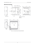
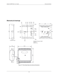
RedLab 201 User's Guide Functional Details Mechanical drawings Figure 7. Circuit board (top) and housing dimensions 12 RedLab 201 User's Guide Functional Details Figure 8. Housing bottom dimensions 13 Chapter 4 Specifications All specifications are subject to change without notice. Typical for 25 °C unless otherwise specified. Specifications in italic text are guaranteed by design. Analog input Table 1. General analog input specifications Parameter Conditions Specification A/D converter type ADC resolution Successive approximation 12 bits Number of channels 8 single-ended Input voltage range Absolute maximum input voltage CHx relative to AGND Input impedance Input bias current Input bandwidth Maximum working voltage Crosstalk Input coupling Sampling rate 10 V input 0 V input –10 V input Small signal (–3 dB) Input range relative to AGND Adjacent channels, DC to 10 kHz –75 dB DC 0.016 S/s to 100 kS/s, software-selectable 100 kS/s max Internal A/D clock Pacer input terminal AICKI Up to eight unique, ascending channels 33 to 4000 S/s typ, system dependent 100 kS/s max, system dependent 15 minutes min Internal pacer External pacer Sample clock source Channel queue Throughput ±10 V ±25 V max (power on) ±25 V max (power off) 1 MΩ (power on) 1 MΩ (power off) –12 µA 2 µA 12 µA 150 kHz ±10.1 V max Software paced Hardware paced Warm-up time Accuracy Analog input DC voltage measurement accuracy Table 2. DC Accuracy components and specifications. All values are (±) Range Gain error (% of reading) Offset error (mV) Absolute accuracy at Full Scale (mV) ±10V 0.098 11 20.8 14 Gain temperature coefficient (% reading/°C) Offset temperature coefficient (mV/°C) 0.016 0.87 RedLab 201 User's Guide Specifications Noise performance For the peak to peak noise distribution test, the input channel is connected to AGND at the input terminal block, and 12,000 samples are acquired at the maximum throughput. Table 3. Noise performance specifications Range Counts LSBrms ±10 V 5 0.76 Analog input calibration Table 4. Analog input calibration specifications Parameter Specification Recommended warm-up time Calibration method Calibration interval 15 minutes min Factory 1 year Digital input/output Table 5. Digital input specifications Parameter Specification Digital type Number of I/O Configuration Pull-up configuration TTL 8 Each bit may be configured as input (power on default) or output The port has 47 kΩ resistors that may be configured as pull-up or pull-down with an internal jumper. The factory configuration is pull-down. 33 to 4000 port reads/writes per second typical, system dependent Digital I/O transfer rate (system-paced) Input low voltage threshold Input high voltage threshold Input voltage limits Output high voltage Output low voltage Output current 0.8 V max 2.0 V min 5.5 V absolute max –0.5 V absolute min 0 V recommended min 4.4 V min (IOH = –50 µA) 3.76 V min (IOH = –24 mA) 0.1 V max (IOL = 50 µA) 0.44 V max (IOL = 24 mA) ±24 mA max 15 RedLab 201 User's Guide Specifications External digital trigger Table 6. External digital trigger specifications Parameter Specification Trigger source Trigger mode TRIG input Software configurable for edge or level sensitive, rising or falling edge, high or low level. Power on default is edge sensitive, rising edge. 1 µs + 1 pacer clock cycle max 125 ns min Schmitt trigger, 47 kΩ pull-down to ground 1.01 V typ 0.6 V min 1.5 V max 2.43 V typ 1.9 V min 3.1 V max 1.42 V typ 1.0 V min 2.0 V max 5.5 V absolute max –0.5 V absolute min 0 V recommended min Trigger latency Trigger pulse width Input type Schmitt trigger hysteresis Input high voltage threshold Input low voltage threshold Input voltage limits External pacer input/output Table 7. External pacer I/O specifications Parameter Specification Terminal names Terminal types AICKI, AICKO AICKI: AICKO: AICKI: AICKO: Input, active on rising edge Output, power on default is 0 V, active on rising edge Receives pacer clock from external source Outputs internal pacer clock Input clock rate Clock pulse width 100 kHz max AICKI: AICKO: 400 ns min 400 ns min Input type Schmitt trigger hysteresis Schmitt trigger, 47 kΩ pull-down to ground 1.01 V typ 0.6 V min 1.5 V max 2.43 V typ 1.9 V min 3.1 V max 1.42 V typ 1.0 V min 2.0 V max 5.5V absolute max -0.5V absolute min 0V recommended min 4.4 V min (IOH = –50 µA) 3.80 V min (IOH = –8 mA) 0.1 V max (IOL = 50 µA) 0.44 V max (IOL = 8 mA) ±8 mA max Terminal descriptions Input high voltage Input low voltage Input voltage limits Output high voltage Output low voltage Output current 16 RedLab 201 User's Guide Specifications Counter Table 8. CTR specifications Parameter Specification Pin name Number of channels Resolution Counter type Input type Counter read/write rates (software paced) CTR 1 channel 32-bit Event counter Schmitt trigger, 47 kΩ pull-down to ground 33 to 4,000 reads/writes per second typ, system dependent Schmitt trigger hysteresis 1.01 V typ 0.6 V min 1.5 V max 2.43 V typ 1.9 V min 3.1 V max 1.42 V typ 1.0 V min 2.0 V max 5.5V absolute max –0.5V absolute min 0V recommended min 1 MHz max 25 ns min 25 ns min Input high voltage threshold Input low voltage threshold Input voltage limits Input frequency High pulse width Low pulse width Memory Table 9. Memory specifications Parameter Specification Data FIFO Non-volatile memory 12 K (12,288) analog input samples 2 KB (768 B calibration storage, 256 B UL user data, 1 KB DAQFlex user data) Power Table 10. Power specifications Parameter Conditions Specification Supply current Typical (Note 1) Maximum (including user voltage, DIO and AICKO loading) 150 mA 500 mA User voltage output terminal (+VO) User voltage output current 4.25 V min, 5.25 V max 100 mA max Note 1: This is the total quiescent current requirement for the device which includes up to 10 mA for the Status LED. This value does not include any potential loading of the digital I/O bits, AICKO, or user voltage. 17 RedLab 201 User's Guide Specifications USB specifications Table 11. USB specifications Parameter Specification USB device type Device compatibility USB cable type USB 2.0 (full-speed) USB 1.1, USB 2.0 A-B cable, UL type AWM 2725 or equivalent. (minimum 24 AWG VBUS/GND, minimum 28 AWG D+/D–) 3 m (9.84 ft) max USB cable length Environmental Table 12. Environmental specifications Parameter Specification Operating temperature range Storage temperature range Humidity 0 °C to 55 °C max –40 °C to 85 °C max 0% to 90% non-condensing max Mechanical Table 13. Mechanical specifications Parameter Specification Dimensions (L × W × H) 117.86 × 82.80 × 28.96 mm (4.64 × 3.26 × 1.14 in.) max Screw terminal connector Table 14. Screw terminal connector specifications Parameter Specification Connector type Wire gauge range Screw terminal 16 AWG to 30 AWG Table 15. Screw terminal pinout Pin 1 2 3 4 5 6 7 8 9 10 11 12 13 14 15 16 Signal name GND TRIG CTR AICKI AICKO GND +VO GND DIO7 DIO6 DIO5 DIO4 DIO3 DIO2 DIO1 DIO0 Pin description Digital ground Digital trigger input Counter input External clock pacer input External clock pacer output Digital ground User voltage output Digital ground DIO channel 7 DIO channel 6 DIO channel 5 DIO channel 4 DIO channel 3 DIO channel 2 DIO channel 1 DIO channel 0 Pin 17 18 19 20 21 22 23 24 25 26 27 28 29 30 31 32 18 Signal name AGND CH7 AGND CH6 AGND CH5 AGND CH4 AGND CH3 AGND CH2 AGND CH1 AGND CH0 Pin description Analog ground Channel 7 Analog ground Channel 6 Analog ground Channel 5 Analog ground Channel 4 Analog ground Channel 3 Analog ground Channel 2 Analog ground Channel 1 Analog ground Channel 0 Meilhaus Electronic GmbH Am Sonnenlicht 2 D-82239 Alling, Germany Phone: +49 (0)81 41 - 52 71-0 Fax: +49 (0)81 41 - 25 71-129 E-Mail: [email protected] http://www.meilhaus.com