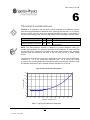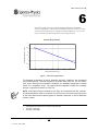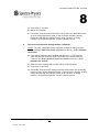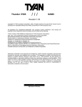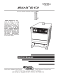
1
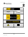
Cyan Laser User’s Guide SPECTRA-PHYSICS A Division of Newport Corporation Cyan Laser User’s Guide Thank you for purchasing a Spectra-Physics product. Your Spectra-Physics Cyan laser is a quality product that has been designed and manufactured to provide reliable performance. The laser head has been designed for use as a component for OEM system integration and is therefore exempt from DHHS performance standard for laser products in accordance with paragraph 1040.10(a)(1). This product is not intended for stand-alone applications such as a bench setup for experimental use. This manual is an important part of your purchase as it will help familiarize you with the laser and explain the numerous features that have been designed into it. Please read this manual thoroughly before using your laser. Please contact Spectra-Physics or your authorized Spectra-Physics distributor should you have questions regarding specific applications or if you require additional information. Contact information: Website: www.newport.com Email: [email protected] Spectra-Physics reserves the right to change or update the contents of this manual and to change the specifications of its products at any time without prior notification. Every effort has been made to keep the information in this document current and accurate as of the date of publication or revision. However, no guarantee is given or implied that this document is error free or that it is accurate with regard to any specification. Spectra-Physics has prepared this manual for use by its customers as a guide for the proper installation, operation and/or maintenance of the Spectra-Physics Cyan laser. Spectra-Physics and the Spectra-Physics Logo are trademarks of Newport, Inc. 2006 Spectra-Physics. All rights reserved. 1355 Terra Bella Avenue Mountain View, California CA 94043 USA. Phone 800.456.2552 Website: WWW.NEWPORT.COM Spectra-Physics Cyan Laser User’s Guide Revision 2, January 2008 Table of Contents 1 - INTRODUCTION 1 2 - LASER SAFETY 3 Safety Summary 3 Precautions for the Safe Operation of Class IIIb Lasers 4 Safety Devices 6 Emission and Power Indicators 6 Shutter 6 Key Switch 6 Safety Interlocks 7 SYSTEM WITH A USER-PROVIDED CONTROL DEVICE 7 Maximum Emission Levels 8 CE RADIATION CONTROL DRAWINGS 8 WASTE ELECTRICAL AND ELECTRONIC EQUIPMENT (WEEE) RECYCLING LABEL 10 3 - LIMITED WARRANTY 11 4 - LASER SPECIFICATIONS 13 ABSOLUTE MAXIMUM RATINGS 13 OPTICAL SPECIFICATIONS 15 MECHANICAL SPECIFICATIONS 16 Umbilical Cable 16 Laser Head Package Diagram 17 Controller Diagram 18 5 - UNPACKING 21 6 - INSTALLATION 23 THERMAL CONSIDERATIONS 24 LASER HEAD MOUNTING 26 Option 1: Mounting the Laser Head to the Spectra-Physics Heatsink 26 Option 2: Mounting the Laser Head to Custom Heatsink 27 CONTROLLER MOUNTING 28 Option 1: Standard Mounting 28 Option 2: Custom Mounting 28 LASER SYSTEM INTERCONNECTION 29 Power Supply Requirements 30 Pin Definition 30 DIP SWITCH SETTINGS 31 Factory Default DIP Switch Settings 31 DIP Switch Settings 32 Spectra-Physics Cyan Laser User’s Guide i Revision 6, January 2008 7 - OPERATING INSTRUCTIONS 33 AUTOMATIC MODE 33 LASER STARTUP 33 LASER ALIGNMENT 34 INTERLOCKS 34 LASER STATUS LEDS 36 LASER HEAD HOURS OF OPERATION LEDS 37 SERIAL COMMUNICATION INTERFACE 38 RS-232 Settings 38 Pin Definition 38 ASCII INTERFACE 8 - SERVICE, MAINTENANCE AND TROUBLESHOOTING 39 44 SERVICE AND MAINTENANCE 44 TROUBLESHOOTING GUIDE 44 Spectra-Physics Cyan Laser User’s Guide ii Revision 6, January 2008 L A S E R S A F E T Y 1 INTRODUCTION This manual contains information you need to safely install, operate, and maintain your Spectra-Physics Cyan laser head, controller and power supply. Included is information on setting up the hardware in preparation for your software control commands. Please be alert to the safety considerations and specific procedures regarding the Spectra-Physics Cyan laser head. Throughout the manual you will see graphic icons representing important information in the text. The purpose of these icons is to provide a visual convention to alert you of a stop in the flow of the manual, where an important note or safety hazard alert is posted. NOTE is an important procedure of which you should be aware before proceeding. CAUTION alerts you of a potential danger to equipment or to the user. WARNING indicates an imminent danger to the user. REMINDER is a helpful hint to procedures listed in the text. The conventions are listed as follows, showing the picture you will see. NOTE CAUTION WARNING REMINDER This manual was designed to be easy to read and understand. If you have any questions or suggestions, please let us know. Spectra-Physics Cyan Laser User’s Guide 1 Revision 6, January 2008 I N T R O D U C T I O N 1 [THIS PAGE INTENTIONALLY LEFT BLANK] Spectra-Physics Cyan Laser User’s Guide 1 Revision 6, January 2008 L A S E R S A F E T Y 2 LASER SAFETY Safety Summary Follow the instructions contained in this manual to ensure proper installation and safe operation of your laser. CAUTION: The Spectra-Physics Cyan lasers are Class IIIb lasers as defined by the Federal Register 21 CFR 1040.10 Laser Safety Standard. The standard requires that certain performance features and laser safety labels be provided on the product. Photographs of the warning labels in place on the laser are shown later in this section. WARNING: This product produces laser light. Diffuse as well as specular beam reflections can cause severe eye or skin damage. Residual invisible light at 976nm wavelength might also be present. NOTE: The laser head has been specifically designed for use as a component for Original Equipment Manufacturer (OEM) system integration and therefore is exempt from DHHS performance standard for laser products in accordance with paragraph 1040.10(a)(1). This product is not intended for standalone applications such as a bench setup for experimental use. The American National Standards Institute publishes a laser safety standard for users entitled American National Standard for the Safe Use of Lasers (ANSI Z136.1). Spectra Physics strongly recommends that laser users obtain and follow the procedures described in this ANSI standard. Copies may be obtained from: American National Standards Institute Inc. 1430 Broadway New York, NY 10018 Or Laser Institute of America 2424 Research Parkway Orlando FL 32826 Spectra-Physics Cyan Laser User’s Guide 3 Revision 6, January 2008 L A S E R S A F E T Y 2 Precautions for the Safe Operation of Class IIIb Lasers • • • • • • • • • • • Users should have an initial eye examination prior to operating the laser equipment followed by periodic re-examinations. Wear protective eyewear at all times; selection depends on the wavelength and intensity of the radiation, the conditions of use and the visual function required. Protective eyewear is available from suppliers listed in the Laser Focus World, Lasers and Optronics, and Photonics Spectra buyer’s guides. Consult the ANSI and ACGIH standards listed at the end of this section for guidance. Maintain a high ambient light level in the laser operation area so the eye’s pupil remains constricted, reducing the possibility of damage. Avoid looking at the output beam; even diffuse reflections are hazardous. Avoid blocking the output beam or its reflections with any part of the body. Establish a controlled access area for laser operation. Limit access to personnel trained in the principles of laser safety. Enclose beam paths wherever possible. Post prominent warning signs near the laser operating area. (See EN 60825-1, ANSI Z136.1 Section 4.7). Install the laser so that the beam is either above or below eye level. Set up shields to prevent any unnecessary specular reflections or beams from escaping the laser operation area. Set up a beam dump to capture the laser beam and prevent accidental exposure. Use of controls or adjustments, or performance of procedures other than those specified herein may result in hazardous radiation exposure There are no user serviceable components in this equipment. You should not attempt repairs on the product; instead, report all problems to Spectra-Physics Customer Service or your local distributor for assistance. Please contact Spectra-Physics, if you have any questions regarding the safe operation of this equipment Operating this laser without due regard for these precautions or in a manner that does not comply with recommended procedures may be dangerous. At all times during installation, maintenance or service of your laser, avoid unnecessary exposure to laser or collateral radiation∗ that exceeds the accessible emission limits listed in “Performance Standards for Laser Products,” United States Code of Federal Regulations, 21CFR1040.10(d) ∗ Any electronic product radiation, except laser radiation, emitted by a laser product as a result of or necessary for the operation of a laser incorporated into that product. Spectra-Physics Cyan Laser User’s Guide 4 Revision 6, January 2008 L A S E R S A F E T Y 2 Do not look at any laser light directly or through any optical lens. When handling the product, do not look directly at the light generated by the product. The laser head will comply with the following safety standards: EN/IEC 60825-1 FDA/CDRH 21 CFR Parts 1040.10-11 Spectra-Physics Cyan Laser User’s Guide 5 Revision 6, January 2008 L A S E R S A F E T Y 2 Safety Devices The images below illustrate the location of the various laser safety devices that will be described in more detail in the following text. Laser Rear View Front View Emission Figure 1: Laser Head Emission and Power Indicators The system provides the following emission and power indicators: • The laser head emission indicator illuminates yellow when there is power to the laser, but no optical emission. (See Figure 1) • The laser head emission indicator illuminates green where there is optical emission. Shutter • The Cyan OEM laser is intended exclusively for use as a component in a master system, and as such, it provides no internal shutter. Key Switch The Cyan OEM lasers are designed to be integrated into a master system that itself complies with regulatory requirements. As such, a key switch is NOT provided with the Cyan OEM laser. However, the user can provide one and connect it using the (optional) analog interface. See Section 7 for more information. Spectra-Physics Cyan Laser User’s Guide 6 Revision 6, January 2008 L A S E R S A F E T Y 2 Safety Interlocks External Interlock The Cyan OEM lasers are designed to be integrated into a master system that itself complies with regulatory requirements. The optional analog interface allows the user to create an external interlock system. See Section 7 for more information. Cover Safety Interlock The Cyan OEM lasers are designed to be integrated into a master system that itself complies with regulatory requirements. As such, the laser head does not have a cover safety interlock. System with a User-Provided Control Device When the Cyan OEM laser system is controlled by a device provided by the user or by software written by the user, the following criteria must be met in order to comply with recognized safety agency requirements: • A keyswitch—must be employed that limits access to the laser and prevents it from being turned on. It can be a real key lock, a removable computer disk, a password that limits access to computer control software, or a similar “key” implementation. The laser must only operate when the “key” is present and in the “on” position. • An emission indicator—must be used to indicate that laser energy is present or can be accessed. It can be a “power-on” lamp, a computer display that flashes a statement to this effect, or an indicator on the control equipment for this purpose. It need not be marked as an emission indicator so long as its function is obvious. Its presence is required on any control panel that affects laser output. Spectra-Physics Cyan Laser User’s Guide 7 Revision 6, January 2008 L A S E R S A F E T Y 2 Maximum Emission Levels The following are the maximum emission levels possible for the Cyan laser. Use this information for selecting appropriate laser safety eyewear and implementing appropriate safety procedures. These values do not imply actual system power or specifications. Laser light at 976 nm is generated in the production of the 488nm emission. This infra-red wavelength is substantially confined to the inside of the laser head. ________________________________________________________________ Emission Wavelength Maximum Power ________________________________________________________________ Laser Output: 488 nm 100 mW CW Fundamental Beam: 976 nm < 1 mW CE Radiation Control Drawings Refer to Table 1. Figure 2: Laser Head Labels Spectra-Physics Cyan Laser User’s Guide 8 Revision 6, January 2008 L A S E R S A F E T Y 2 Laser Head Left Side Label (1) Head Serial Number Label (2) Model Number Label (3) Laser Head Top Label (4) Laser Head Right Side Label (5) Emission Indicator Caution Label (6) Warranty Seal (7) Table 1: Laser Head Labels Spectra-Physics Cyan Laser User’s Guide 9 Revision 6, January 2008 L A S E R S A F E T Y 2 Waste Electrical and Electronic Equipment (WEEE) Recycling Label To Our Customers in the European Union: As the volume of electronics goods placed into commerce continues to grow, the European Union is taking measures to regulate the production and disposal of waste from electrical and electronic equipment. Toward that end, the European Parliament has issued directives instructing European Union member states to adopt legislation concerning the reduction, recovery, re-use and recycling of waste electrical and electronic equipment. The directive addressing the reduction, recovery, re-use and recycling of waste electrical and electronic equipment is referred to as WEEE. In accordance with this directive, the accompanying product has been marked with the WEEE symbol. See Label 9 in Table 1. The main purpose of the symbol is to designate that at the end of its useful life, the accompanying product should not be disposed of as normal municipal waste, but should instead be transported to a collection facility that will ensure the proper recovery and recycling of the product's components. The symbol also signifies that this product was placed on the market after 13 August, 2005. At this time, regulations for the disposal of waste electrical and electronic equipment vary within the member states of the European Union. Please contact a Newport / Spectra-Physics representative for information concerning the proper disposal of this product. Spectra-Physics Cyan Laser User’s Guide 10 Revision 6, January 2008 L A S E R S P E C I F I C A T I O N 3 LIMITED WARRANTY At Spectra-Physics, we take great pride in the reliability of our products. Considerable emphasis has been placed on controlled manufacturing methods and quality control throughout the manufacturing process. Nevertheless, even the finest precision instruments will need occasional service. We feel our instruments have excellent service records compared to competitive products, and we hope to demonstrate, in the long run, that we provide excellent service to our customers in two ways: first by providing the best equipment for the money, and second, by offering service facilities that get your instrument repaired and back to you as soon as possible. Spectra-Physics maintains major service centers in the United States, Europe, and Japan. Additionally, there are field service offices in major United States cities. When calling for service, dial our toll free number: 1 (800) 456-2552 in the United States, or 1 (650) 961-2550 from anywhere else. WARRANTY - This warranty supplements the warranty contained in the specific sales order. In the event of a conflict between documents, the terms and conditions of the sales order shall prevail. Unless otherwise specified, all parts and assemblies manufactured by Spectra-Physics are unconditionally warranted to be free of defects in workmanship and materials for a period of one year following delivery of the equipment to the F.O.B. point. Liability under this warranty is limited to repairing, replacing or giving credit for the purchase price of any equipment that proves defective during the warranty period, provided prior authorization for such return has been given by an authorized representative of Spectra-Physics. Spectra-Physics will provide at its expense all parts and labor and one- way return shipping of the defective part or instrument (if required). In- warranty repaired or replaced equipment is warranted only for the remaining portion of the original warranty period applicable to the repaired or replaced equipment. This warranty does not apply to any instrument or component not manufactured by Spectra-Physics. When products manufactured by others are included in Spectra-Physics equipment, the original manufacturer's warranty is extended to Spectra-Physics customers. When products manufactured by others are used in conjunction with Spectra-Physics equipment, this warranty is extended only to the equipment manufactured by Spectra-Physics. This warranty also does not apply to equipment or components that, upon inspection by Spectra-Physics, discloses to be defective or unworkable due to abuse, mishandling, misuse, alteration, negligence, improper installation, unauthorized modification, damage in transit, or other causes beyond the control of Spectra-Physics. Spectra-Physics Cyan Laser User’s Guide 11 Revision 6, January 2008 L A S E R S P E C I F I C A T I O N 3 This warranty is in lieu of all other warranties, expressed or implied, and does not cover incidental or consequential loss. The above warranty is valid for units purchased and used in the United States only. Products shipped outside the United States are subject to a warranty surcharge. RETURN OF THE INSTRUMENT FOR REPAIR - Contact your nearest Spectra-Physics field sales office, service center, or local distributor for shipping instructions or an on-site service appointment. You are responsible for one-way shipment of the defective part or instrument to Spectra-Physics. We encourage you to use the original packing boxes to secure instruments during shipment. If shipping boxes have been lost or destroyed, we recommend that you order new ones. We can return instruments only in Spectra-Physics containers. Spectra-Physics Cyan Laser User’s Guide 12 Revision 6, January 2008 L A S E R S P E C I F I C A T I O N 4 LASER SPECIFICATIONS The following specifications are for the 10-mW, 20-mW and 40-mW Spectra-Physics Cyan lasers. Absolute Maximum Ratings The following limits are the absolute maximum ratings. Operation beyond any of these limits may result in permanent damage to the laser. Parameter Min Max Units Storage Temperature –30 +70 °C 0 100 % Storage Relative Humidity * Ambient Operating Temperature 4 40 °C Baseplate Operating Temperature 4 55 °C 90 % Non-Operating Altitude 0 70,000 feet Operating Altitude 0 10,000 feet –0.3 +13 V 7 min Temperature Ramp 0.5 °C/min Total Power Dissipation < 30 W Vibration (50 to 500 Hz sinusoidal 0.25 octaves/min) 3 G Shock Tolerance (11 ms laterally or vertically) 25 G Operating Relative Humidity ** +12 V Supply Pin Voltage (+12 V rail with respect to GND) Warm-Up Time from OFF * Non-condensing. ** Non-condensing—see graph on next page. Table 2: Absolute Maximum Ratings Spectra-Physics Cyan Laser User’s Guide 13 Revision 6, January 2008 L A S E R S P E C I F I C A T I O N 4 Relative Humidity [%] Ambient-Temperature and Relative-Humidity Operating Range 90 90 80 80 70 70 60 60 50 50 40 40 30 30 20 20 10 10 0 0 4 6 8 10 12 14 16 18 20 22 24 26 28 30 32 34 36 38 40 o Ambient Temperature [ C] Figure 3: Temperature and Relative Humidity Operating Region Spectra-Physics Cyan Laser User’s Guide 14 Revision 6, January 2008 L A S E R S P E C I F I C A T I O N 4 Optical Specifications The following table lists the optical specifications of the 10-mW, 20-mW and 40-mW Spectra-Physics Cyan lasers. Parameter Conditions Min Wavelength Nom Max 488.0 Wavelength Accuracy Output Power 10-mW product 20-mW product 40-mW product Output Power Stability Short term Long term Maximum IR Output Power Noise 20 Hz – 2 MHz, RMS 20 Hz – 20 kHz, pk–pk 2 hours, +/- 3°C Polarization Extinction Ratio Perpendicular to baseplate –0.5 10 20 40 Power in Band 12 22 42 -1 -5 100:1 nm +0.5 nm 15 27 49 mW mW mW +1 +5 0.1 % % mW 0.20 1 % % 250:1 98 % Mx2 1.1 My2 1.1 Beam Asymmetry At beam waist Beam Diameter @ 1/e2 1:1.1 0.65 0.75 mm 1.1 mrad –30 +30 µrad –0.25 –2.5 +0.25 +2.5 mm mrad –200 +200 mm Beam Divergence Pointing Stability 3 hours, +/- 3°C Static Alignment Tolerances Beam Position Beam Angle Beam Waist Position With respect to laser exit port Table 3: Optical Specifications Spectra-Physics Cyan Laser User’s Guide 15 Revision 6, January 2008 Units L A S E R S P E C I F I C A T I O N 4 Mechanical Specifications The mechanical assembly consists of: Umbilical cable – connects the module controller to the laser head. Laser head – incorporates all optical components and trans-impedance amplifiers. Module controller – incorporates all electronics for interfacing and control of the laser head and fan. The following mechanical components are optional: Heat sink and integral fan DC power supply Umbilical Cable The standard umbilical cable is a 2-meter-long 25-conductor 24 AWG shielded cable wired straight through, with a standard 25-pin DB-25 connector on each end. The end connecting to the laser head is female and the end connecting to the controller is male. A 2-foot version is available as an option. Stated laser performance is only guaranteed with these Spectra-Physics-provided cables. Spectra-Physics Cyan Laser User’s Guide 16 Revision 6, January 2008 L A S E R S P E C I F I C A T I O N 4 Laser Head Package Diagram The following drawing shows the dimensions (in millimeters), interfaces, and mounting features of the laser head. The free-space optical output of the module is also specified. The back connector is a 25-pin male DB-25. The fan connector is a 3-pin AMP MTE header. The emission indicator is bi-color: yellow and green. It is illuminated yellow when power is applied to the laser head. It is illuminated green when more than approximately 50 mA of current is supplied to the laser’s gain chip. FRONT VIEW TOP VIEW REAR VIEW A EMISSION INDICATOR B C J K FAN POWER L M F E D BEAM EXIT WINDOW N (4HOLES) G H SYMBOL DIMENSION SYMBOL DIMENSION A 120 J 17.5 B 5 K 19.0 C 7.5 L 6 D 55 M 34 E 70 N 4 F 10.3 G 105.5 H 125 25-PIN D-SUB (PLUG) ALL DIMENSIONS ARE IN MILLIMETERS Figure 4: Laser Head The bore sighting reference surfaces are the bottom of the baseplate and the left edge of the laser head looking into the beam exit window. Spectra-Physics Cyan Laser User’s Guide 17 Revision 6, January 2008 L A S E R S P E C I F I C A T I O N 4 Controller Diagram The following diagram shows the dimensions (in millimeters), interfaces, and mounting features of the controller. DC power is connected in from the top of the controller through a Molex Micro-Fit 10-pin connector. The front of the controller supports a 25-pin DB-25 connector for attachment of the module umbilical cable linking the controller to the laser head. The rear of the controller supports a 9-pin DB-9 connector for attachment of an RS-232 cable for remote control as well as a 25-pin DB-25 connector for attachment of the module controller to a customer-supplied analog control circuit. This DB-25 connector is keyed by blocking pin 17 to prevent accidental connection of the laser head to the analog interface. The user can buy a standard cable and cut off pin 17 to match the analog interface. PLAN VIEW DC POWER INPUT LED INDICATORS (OP. HOURS) COMPONENT BOUNDARY SIDE VIEW REAR VIEW F G H FRONT VIEW ANALOG CONTROL (OPTIONAL) UMBILICAL CABLE, DB-25 RECEPTACLE SERIAL LINK, DB-9 RECEPTACLE ANALOG INTERFACE, DB-25 RECEPTACLE 215.56 B 76.25 C 66.05 D 107.54 E 97.82 F 6.35 G 23.85 H 43.45 J 8-32 UNC A J (6 HOLES) C DIMENSION A B SYMBOL ALL DIMENSIONS ARE IN MILLIMETERS D E BOTTOM VIEW Figure 5: OEM Controller Spectra-Physics Cyan Laser User’s Guide 18 Revision 6, January 2008 tam_030131 L A S E R S P E C I F I C A T I O N 4 Heatsink and Fan Assembly Diagram The following diagram shows the dimensions of the heatsink and fan assembly. FRONT VIEW SIDE VIEW BACK VIEW 207 180 50 12.8 102.5 80 AIRFLOW 71.6 70 35 5.4 BOTTOM VIEW 150 8.5 ALL DIMENSIONS ARE IN MILLIMETERS 4.5 127 72 20.2 70.4 7 127 150 Figure 6: Heatsink Pin # Symbol Description 1 Unused 2 FAN+ Fan power source (12 V) 3 FAN- Fan power return No connection Table 4: Fan Connector Pin Assignment Spectra-Physics Cyan Laser User’s Guide 19 Revision 6, January 2008 69 L A S E R S P E C I F I C A T I O N 4 [THIS PAGE INTENTIONALLY LEFT BLANK] Spectra-Physics Cyan Laser User’s Guide 20 Revision 6, January 2008 U N P A C K I N G 5 UNPACKING All Spectra-Physics products are inspected and tested prior to shipment from the factory. In the event that there is damage to the shipping container (holes or crushing, etc.) insist that a representative of your shipping carrier is present while you unpack the contents. Damage caused by shipping is the responsibility of the shipping carrier and all claims must be routed through their claims department. NOTE: a) Like all electronic devices, this device contains static sensitive components. It should be handled only with proper Electrostatic Discharge (ESD) grounding procedures. OBSERVE all ESD precautions and procedures while handling the product. Ensure you and any surfaces that the product lies on are correctly grounded. b) CAREFULLY unpack the contents from the box. c) Check contents of the box against the packing list to assure all parts have been received. d) Inspect each item to assure it is not damaged. Ensure to use full ESD precautions as parts are ESD sensitive. e) It is recommended that you keep the shipping package until the unit has been installed and verified as being fully operational. Spectra-Physics Cyan Laser User’s Guide 21 Revision 6, January 2008 U N P A C K I N G 5 [THIS PAGE INTENTIONALLY LEFT BLANK] Spectra-Physics Cyan Laser User’s Guide 22 Revision 6, January 2008 I N S T A L L A T I O N 6 INSTALLATION This chapter describes the setup and installation of the laser head and controller. Please read and understand this chapter thoroughly before proceeding with the laser installation. The Spectra-Physics Cyan laser consists of a laser head and module controller joined by an umbilical cable, an optional Spectra-Physics DC power supply and an optional Spectra-Physics heatsink and fan assembly (see Chapter 4 “Laser Specifications” for a detailed mechanical description of each item). Additionally, the module can be controlled and monitored via one of two system interfaces on the module controller: either a RS-232 physical command interface or a 25-pin DB-25 analog interface. Spectra-Physics Cyan Laser User’s Guide 23 Revision 6, January 2008 I N S T A L L A T I O N 6 Thermal Considerations CAUTION: It is imperative that the laser head be attached to an adequate heatsink with thermal grease/heatsink compound when operating (see footnote* on next page). Failure to attach the laser head to an adequate heatsink will result in overheating of the laser head causing a laser shutdown and possibly causing damage to the laser head. Thermal Specifications Min Max Description Ambient Operating Temperature 4°C 40°C Baseplate Operating Temperature 4°C 55°C Worst-case environmental limits. Operation outside this range will result in thermal shutdown. NOTE: The Spectra-Physics heatsink is designed to provide adequate cooling for reliable laser operation. For effective operation of the heatsink it is imperative that the heatsink fan be connected to the laser head via the cable provided. Also, adequate clearance must be provided at the back of the unit near the fan to ensure proper airflow. The maximum thermal load of the laser head module under worst-case environmental conditions is < 14 W for steady-state operation and < 19 W during the startup procedure. The following graph shows the typical steady-state thermal load for a range of baseplate temperatures and a heatsink thermal impedance of 0.55ºC/W. Typical Laser Head Power Dissipation 14 12 Thermal Load [W] 10 8 6 4 2 0 0 5 10 15 20 25 30 35 40 o Baseplate Temperature [ C] Table 5: Typical Laser Head Power Dissipation Spectra-Physics Cyan Laser User’s Guide 24 Revision 6, January 2008 45 50 55 I N S T A L L A T I O N 6 The following graph shows the maximum allowable heatsink thermal impedance necessary to maintain the required maximum baseplate temperature of 55ºC for a range of environmental temperatures. For example, an ambient temperature of 35ºC would require a heatsink with a thermal impedance not exceeding 0.95ºC/W. He atsink Re quire me nts 2.5 Thermal Impedance [ o C/W] 3 2 1.5 1 0.5 0 0 5 10 15 20 25 30 35 40 o Am bient Tem perature [ C] Figure 7: Heat Sink Requirements To guarantee performance across all allowable operating conditions, we recommend using a heatsink with a thermal impedance no greater than 0.65ºC/W. This will ensure that, under worst-case environmental conditions, the baseplate temperature remains within the acceptable range. The Spectra-Physics-supplied heatsink/fan assembly delivers a typical performance of 0.55ºC/W. NOTE: If the Spectra-Physics heatsink is not used, we recommend that the customerprovided heatsink be milled to a flatness of 0.05 mm over the entire mounting surface of the laser head and that thermal grease or heatsink compound* is used to maximize thermal contact. * The following thermal greases/heatsink compounds (or equivalent) are recommended: • Wakefield Engineering Non-silicone Thermal Compound 126-4 • Thermagon T-Putty 504 • Thermagon T-Mate 2905C Spectra-Physics Cyan Laser User’s Guide 25 Revision 6, January 2008 I N S T A L L A T I O N 6 Laser Head Mounting The following describes the procedure for mounting the Spectra-Physics Cyan laser head to the heatsink. You will need: - 4 x screws (supplied as part of the installation kit) o type: M3 x 0.5 x 12 mm - 4 x dished internal-external toothed washers (electrically conductive, supplied as part of the installation kit) - thermal grease (not supplied) - calibrated torque screwdriver (not supplied). NOTE: The laser head must be electrically grounded in order to meet the ESD requirements of the laser head. REMINDER: It is important that the laser head be attached with thermal grease to an adequate heatsink when operating. Failure to attach the laser head with thermal grease to an adequate heatsink will result in overheating of the laser head causing a laser shutdown and possibly cause damage to the laser head. Option 1: Mounting the Laser Head to the Spectra-Physics Heatsink CAUTION: Ensure that both surfaces at the laser head-heatsink interface are clean and a light coating of thermal grease is applied. Any voids may cause heat dissipation problems with the laser head. Uneven application of thermal grease may result in deviation from intended boresighting. - Align the laser head against the 3 reference locator pins on the heatsink. See diagram on next page. Insert the toothed washers on the M3 screws. Ensure that the concave surface of the washer faces away from the screw head. Loosely tighten the four screws with washers into the attachment holes on the heatsink in diagonal order. Tighten the four screws in diagonal order using a torque screwdriver set to a maximum torque of 100 N cm. Spectra-Physics Cyan Laser User’s Guide 26 Revision 6, January 2008 I N S T A L L A T I O N 6 Align the laser head into the 3 reference locator pins on the heatsink Figure 8: Laser Head Alignment on Heatsink Option 2: Mounting the Laser Head to Custom Heatsink CAUTION: Ensure that both surfaces of the laser head-heatsink interface are clean and that a light coating of thermal grease is applied. Any voids may cause heat dissipation problems with the laser head. Uneven application of thermal grease may result in deviation from intended boresighting. It is recommended that the customer-supplied heatsink include reference locator pins to ensure proper alignment of the laser head (see figure above). The mounting procedure follows as described in Option 1 above. Spectra-Physics Cyan Laser User’s Guide 27 Revision 6, January 2008 I N S T A L L A T I O N 6 Controller Mounting The controller must be mounted to an electrically conductive, grounded surface, at all 6 mounting points, using the components outlined below: - - 6 electrically conductive screws (not supplied) o type: UNC No. 8 o length: customer-specific, depending on mounting site. 6 electrically conductive tooth shaped lock washers NOTE: You will need to determine the length of the screws required to attach the Spectra-Physics module controller to your mounting position. IMPORTANT: In all installations the controller card should be mounted in a way that the exposed electronics is not accessible to an end user. To protect against issues that could result from electrostatic discharge from an end user, the only parts of the controller that should be possible to physically touch are the RS232 interface connector, the umbilical cable connector, and the analog interface connector (if installed). Option 1: Standard Mounting Each module controller comes pre-assembled with 6 standoffs for mounting purposes. Each standoff requires one UNC No. 8 screw (not supplied). See Controller Diagram in Ch. 4. Place module controller with all stand-off pins on the flat electrically conductive mounting surface and use screws to attach. Option 2: Custom Mounting Each standoff can be carefully removed and any number of custom mounting techniques can be used. If you choose to mount using another method, ensure that there is adequate electrical conductivity between the module controller and mounting surface by using electrically conductive screws ad electrically conductive tooth shaped lock washers. Spectra-Physics Cyan Laser User’s Guide 28 Revision 6, January 2008 I N S T A L L A T I O N 6 Laser system Interconnection The full diagram of the laser interconnection is shown below. CAUTION: Do not apply power until all cables and connections have been attached. The umbilical cable must be screwed into place prior to operating the laser. Components supplied by Spectra-Physics are not hot switchable. Damage may be caused by current surges if power is applied while attaching or removing cables. CUSTOMER-SUPPLIED COMPONENTS ANALOG CONTROL ELECTRONICS COMPUTER CONTROL ANALOG INTERFACE RS-232 INTERFACE MODULE CONTROLLER LASER HEAD UMBILICAL CABLE FAN POWER DC POWER OPTIONAL COMPONENTS AC/DC POWER SUPPLY HEAT SINK WITH INTEGRATED FAN Figure 9 : Laser System Interconnection Spectra-Physics Cyan Laser User’s Guide 29 Revision 6, January 2008 I N S T A L L A T I O N 6 DC Power Supply Interface DC power to the module controller is supplied via a 10-pin Molex connector (Molex Part# 43025-1000 for the receptacle, and Molex Part# 43030-0009 for each terminal). A Molex receptacle and 10 terminals are supplied as part of the controller installation kit. Power Supply Requirements Parameter Power Supply Voltage, +12 V rail Power Supply Current Min Nom. Max Units 11 12 13 V 1 % pk-pk 4000 Power Supply Noise (20 Hz to 20 MHz) mA Table 6 : Power Supply Requirements Pin Definition Figure 10: Molex (Power) Connector NOTE: The pinout convention used here differs from the Molex pin definition. The following table defines the pinout and pin attributes of the DC power supply physical interface (Molex connector required to interface into the module controller), which also includes the interlock loops. Pin # Symbol 1 V+12 2 V+12 3 4 5 6 GND GND INTERLOCK+ INTERLOCK- Description Power supply DC voltage, +12 V. Use both pins due the high current requirements. The module controller is installed with a polyswitch protecting the 12-V rail. The trip point is 8.0 A @ 20ºC Power supply ground return. Use both pins due to the high current requirements Power supply connector interlock + Power supply connector interlock - Spectra-Physics Cyan Laser User’s Guide 30 Revision 6, January 2008 I N S T A L L A T I O N 6 7 KEYSWITCH (NC) 8 KEYSWITCH (NO) 9 10 KEYSWITCH COMMON CHASSIS Laser safety keyswitch normally closed. Laser operates when pin 7 is connected to pin 9 Laser safety keyswitch normally open. Laser switches off when pin 8 and pin 9 are connected Laser safety keyswitch common Chassis ground Table 7: Molex Connector Pin Description DIP Switch Settings The interlock loop override DIP switches can be found on the module controller as shown in the figure below. Figure 11: Control DIP Switch Illustration Factory Default DIP Switch Settings The interlock loop override DIP switches (S1) on the module controller come preset with factory default settings of: S1-1 S1-2 S1-3 S1-4 OFF OFF OFF OFF : : : : interlock on analog interface is required interlock at DC power connector is required keyswitch at DC power connector is required controller autoboot is disabled Spectra-Physics Cyan Laser User’s Guide 31 Revision 6, January 2008 I N S T A L L A T I O N 6 DIP Switch Settings Switch S1 Position Interlock Loop OFF Analog Interlock Loop ENABLED For normal laser operation, user must have a wire loop between pin 1 and 3 in analog interface DB-25 connector ON Analog Interlock Loop DISABLED Analog interface interlock loop disabled OFF Power Interlock Loop ENABLED For normal laser operation, user must have a wire loop between pin 5 and 6 in controller power supply Molex connector ON Power Interlock Loop DISABLED Power interlock loop disabled OFF Laser Safety Keyswitch ENABLED For normal laser operation, laser safety keyswitch must close a wire loop between pin 7 and 9 in controller power supply Molex connector ON Laser Safety Keyswitch DISABLED Keyswitch not required to close interlock loop OFF Controller Automatic Boot DISABLED Laser controller waits for a RS232C or analog interface command to start laser ON Controller Automatic Boot ENABLED Laser will start automatically after DC power is supplied 1 2 3 Description 4 Table 8: Dip Switch Setting Description NOTE: Changes to DIP switch positions should not be done when there is power applied to the laser controller. The DIP switches are a maintenance feature only and are not intended to be operated during normal operation. As with the remainder of the controller card, the electronics should not be exposed to contact from an end user. Spectra-Physics Cyan Laser User’s Guide 32 Revision 6, January 2008 O P E R A T I N G I N S T R U C T I O N S 7 OPERATING INSTRUCTIONS Automatic Mode REMINDER: The factory default settings on the module controller interlock loop override DIP switches are such that Automatic Mode is disabled (DIP switch S1-4 = OFF) and all interlock loops are enabled (DIP switches S1-1, S1-2, S1-3 = OFF). In this mode the laser will not power on (when DC power is applied) without external intervention and unless all interlock loops are closed. To set the laser to start automatically using its default parameters, set the DIP Switch S1-4 = ON. Depending on the status of the remaining interlock DIP switches, the laser will activate upon power-up. Laser Startup The Spectra-Physics Cyan laser will typically start up in less than 5 minutes (some extreme operating conditions may require up to 7 minutes.) During the startup interval the laser controller performs an auto-calibration sequence. The output power will fluctuate from very low levels to up to 20% above the rated output power during this interval. The state of the laser is reflected in the laser head Status LED located on the controller: LED LASER HEAD STATUS Color Description RED Laser head is OFF YELLOW GREEN GREEN FLASHING Laser head operating and in warm-up state Laser head operating and locked at specified 488-nm output power Laser head operating in APCOFF mode (see APCOFF command) Table 9: Laser Head Status Light Description Spectra-Physics Cyan Laser User’s Guide 33 Revision 6, January 2008 O P E R A T I N G I N S T R U C T I O N S 7 Laser Alignment Care should always be exercised to prevent direct, strong backreflections from returning to the laser through the output port. We recommend the use of antireflection-coated optics for delivery of the laser beam; we also recommend that flat optical surfaces (such as plano-convex lenses, filters, etc.) be angled slightly away from normal incidence. While these should be standard practices, in order to provide an additional measure of robustness, the Spectra-Physics Cyan laser has been designed to be tolerant of small amounts of backreflected light. The laser output power is guaranteed to remain within specification even when a reflection from a typical glassair interface, less than about 5% of the full laser power, is backaligned into the laser. Depending on the alignment procedures used, sometimes it becomes convenient to temporarily direct the laser’s output beam back onto itself. In order to assist with this, we provide a control feature: Automatic Power Control disable (see ASCII Interface APCOFF command). When the APCOFF command is invoked over the ASCII interface, the laser will operate at constant current and will therefore become insensitive to any backreflection of laser light. APCOFF is intended only for temporary conditions—the default operation of the laser is for Automatic Power Control to be enabled. When the APCOFF command is in effect, the laser head status LED on the controller board will flash green. After APC is restored, the laser may take up to a few minutes to reach the specified power stability. Interlocks The Spectra-Physics Cyan module controller has 3 interlock mechanisms. Any or all of the interlocks can be used. The interlock circuit is shown below. If the interlock circuit is open, either at startup of the laser head or when the laser head is operational, the laser enters the interlocked state, causing the laser head to shut down. To re-enable the laser head, the interlock circuit must be closed and the laser controller must be power cycled. Using the Analog Interlock To use the analog interlock, set the DIP switch S1-1 to OFF. The laser will now not operate until a closed loop exists between pins 1 and 3 on the analog interface DB-25 connector. Using the DC Power Connector Interlock To use the DC power connector interlock, set the DIP switch S1-2 to OFF. The laser will now not operate until a closed loop exists between pins 5 and 6 on the DC power (Molex) connector. Spectra-Physics Cyan Laser User’s Guide 34 Revision 6, January 2008 O P E R A T I N G I N S T R U C T I O N S 7 Using the Keyswitch Interlock A keyswitch may be connected to the Spectra-Physics Cyan module controller at the DC power (Molex) connector pins 7, 8 and 9. See the Diagram on the next page. To use the keyswitch interlock, set the DIP switch S1-3 to OFF. The laser will now not operate until a closed loop exists between pins 7 and 9 on the DC power (Molex) connector. Figure 12: Interlock Circuit Diagram Spectra-Physics Cyan Laser User’s Guide 35 Revision 6, January 2008 O P E R A T I N G I N S T R U C T I O N S 7 Laser Status LEDs Four LEDs are used to indicate the operational status of the laser head and of the module controller. Figure 13: LED Status Lights The following table describes the possible states for each laser Status LED. LED Color OFF POWER GREEN RED YELLOW LASER HEAD STATUS INTERLOCK LOOP OPEN INTERLOCK OVERRIDE GREEN GREEN FLASHING OFF Description Power OFF: regulated power is either off or below 3.3 V DC Power ON: regulated power is on (3.3 V DC) Laser head is OFF Laser head operating and in warm-up state Laser head operating and locked at specified 488nm output power Laser head operating in APCOFF mode (see APCOFF command) Interlock loop is closed RED Interlock loop is open OFF Interlock overrides are disabled RED An interlock override is enabled Table 10: LED Status Light Description Spectra-Physics Cyan Laser User’s Guide 36 Revision 6, January 2008 O P E R A T I N G I N S T R U C T I O N S 7 Laser Head Hours of Operation LEDs Five green LEDs are used to show the laser head hours of operation in a binary code. This display allows readouts up to 31000 hours in 1000-hour increments. Figure 14: Laser Head Operating Hour LEDs The LEDs are marked on the module controller with “1”, “2”, “4”, “8”, and “16”, with the LED marked as “1” indicating the Least Significant Bit (LSB) of the binary code. The following table shows some examples of LED output for different values of the laser head hours of operation. LED “16” OFF OFF OFF LED “8” OFF OFF OFF LED “4” OFF OFF OFF OFF OFF ON ON OFF OFF ON ON ON LED “2” OFF OFF ON …….. OFF …….. OFF …….. ON LED “1” OFF ON OFF Hours 0 to 999 1000 to 1999 2000 to 2999 ON 5000 to 5999 OFF 16000 to 16999 ON > 31000 Table 11: Laser Head Hour LED Description Spectra-Physics Cyan Laser User’s Guide 37 Revision 6, January 2008 O P E R A T I N G I N S T R U C T I O N S 7 Serial Communication Interface The Spectra-Physics Cyan module controller firmware supports RS-232 physical command interface. RS-232 Settings The default setting for the serial communication interface is: • • • • 19200 baud no parity 8 data bits 1 stop bit Flow control must be set to “None”. Pin Definition The following table defines the pinout and pin attributes of the RS-232 physical command interface. Pin # Symbol 1 UNUSED 2 TXD O Transmit data 3 RXD I Receive data 4 UNUSED Not connected 5 GND Ground return UNUSED Not connected 6-9 I/O Description Not connected Table 12: Serial Interface Pinout Spectra-Physics Cyan Laser User’s Guide 38 Revision 6, January 2008 O P E R A T I N G I N S T R U C T I O N S 7 ASCII Interface The controller supports an ASCII interface. ASCII characters are sent to the module over the serial interface. The interface recognizes two types of interaction: a query (read) or command (write). Query format : Command format : “?<COMMAND><CR>” “<COMMAND><CR>” or “<COMMAND> =<VALUE><CR>” The character <CR> stands for Carriage Return only (ASCII character #13); a Line Feed character (ASCII character #10) should not be used. The following table summarizes the ASCII mode command set. Command Type > Query/Command APCOFF Query/Command BT Query C Query CLS Command CT Query DT Query DST Query E Query/Command F Query Description This command turns on/off the command prompt. 1=ON, 0=OFF When set to 1, the laser’s Automatic Power Control is disabled. In this state the laser is tolerant of back-reflection. It is advised that this feature be used when aligning the laser in case light is reflected back into the laser. When reset to 0 the laser is restarted with Automatic Power Control enabled. The default value is 0 Reads the baseplate temperature. Value returned is in degrees Celsius Returns gain chip current in amperes Clears text from serial communication screen (only when VT100 emulation is being used) Reads the crystal temperature. Value returned is in degrees Celsius Reads the bench temperature in degrees Celsius Reads the bench set temperature in degrees Celsius Sets/reads Echo Off feature. This turns on/off character echo on serial communication terminal. This feature is useful if a computer script/program rather than a person is controlling the laser. 1=ON, 0=OFF This query checks for faults in the system and if there is one, it returns that fault number. If there are multiple faults present in the system, it returns the first fault detected from a list of faults. See “?FL” or “?FF” queries for different ways to receive fault status Spectra-Physics Cyan Laser User’s Guide 39 Revision 6, January 2008 O P E R A T I N G I N S T R U C T I O N S 7 Command FL Type Query FF Query HH Query Description This command checks for faults in the system and if there is one, it returns a list of all faults present. If there is no fault in the system, it says “None”. This command shows faults in text rather than in number(s). The numbers listed below are not shown as a result of the query but reflect the number returned by the F query. See “?F” or “?FF” queries for different ways to receive fault status. Fault list: 0 None 1 External Interlock Fault 2 Bench Temperature Fault 3 Baseplate Temperature Fault 4 Not Implemented 5 Gain Chip Current Fault 6 Analog Interface Fault 7 Not Implemented 8 Not Implemented 9 System Warming 10 Head EEPROM Fault 11 Controller EEPROM Fault 12 Crystal Temperature Fault 13 Power Fault 14 ADC Fault 15 Warming Fault 16 Controller Fault This command checks for faults in the system and if there is one, it returns a two-byte event code. The bits in the code are defined below. Bit 0 is the least significant bit. Fault list: 0 External Interlock Fault 1 Bench Temperature Fault 2 Baseplate Temperature Fault 3 Not Implemented 4 Gain Chip Current Fault 5 Analog Interface Fault 6 Not Implemented 7 Not Implemented 8 System Warming 9 Head EEPROM Fault 10 Controller EEPROM Fault 11 Crystal Temperature Fault 12 Power Fault 13 ADC Fault 14 Warming Fault 15 Controller Fault Returns the usage hours stored in the head EEPROM. Head hours are updated every time there is at least minimum current flowing through the gain chip Spectra-Physics Cyan Laser User’s Guide 40 Revision 6, January 2008 O P E R A T I N G I N S T R U C T I O N S 7 Command Type Description HID Query I Query/ Command K Query L Query/Command P Query/Command PSH Query PST Query SF Query/ Command SV Query Reads the head ID This command is used to query the interlock loop status. If the value return is 1, then the interlock is loop is open. After closing the interlock loop physically, this command can be used to reset the interlock state. 0=CLOSE, 1=OPEN Reads status of key switch This command is used to read or set the on/off status. Setting L=1 will turn on the laser. Setting L=0 will turn off the laser This command is used to read the laser power. A query returns the read power level in mW. Returns the usage hours stored in the controller EEPROM. This value represents the on time of the controller. This value starts updating every time the controller is turned on This query is used to read the controller temperature. This is a value in degrees Celsius This command is used to set the laser gain chip current scale factor. The value written to this register scales the gain chip current read by the “C” query. Valid values are between 0 and 10 with up to two decimal places. The default value is 1 Reads the software version SVH Query T Query Reads the software version stored in the laser head EEPROM Reads TEC control status. 0=OFF, 1=ON Table 13: ASCII Interface Command Description Spectra-Physics Cyan Laser User’s Guide 41 Revision 6, January 2008 O P E R A T I N G I N S T R U C T I O N S 7 The laser output can be controlled via the analog interface connector. The connector is a standard DB-25 pin female connector. The analog interface DB-25 pin 17 is keyed in order to avoid mismatching with the DB-25 laser head connector. A standard cable can be used; cut DB-25 pin 17 to match with analog interface input connector. Pin # Signal Name 1 (+) Analog Interlock Loop 3 (-) Analog Interlock Loop 2 Laser On/Off 4, 5, 6 NC 7 NC 8 Power Monitor 9 LD I Monitor 10, 11 GND 12 NC 13 V out I/O – Signal level Description < 15 VDC, 12.5 mA typ. Connect pins 1 and 3 together to close interlock loop for normal operation. To disable the analog interface interlock loop, set main controller DIP switch S1-1 to ON Input 0: < 0.4 V 1: > 3.5 V 0 = Turn laser and TEC controller OFF 1 = Turn laser and TEC controller ON If pin left open, the default value is 1 (laser, TEC ON) No connection Output monitor V Analog output signal, 10 mA max. Used to remotely monitor the laser output power. 0.1V/mW Output monitor V Gain chip current monitor, 10 mA max, 1 V/A Main PCB signal ground No connection Output +12 V + 12 V, 100 mA max power supply 14 GND 15 Bench Temperature Monitor Output monitor V 0 to 4.096 V signal output corresponding to a 0 to 100 degrees laser head bench temperature 16 Laser locked Output 0: < 0.4 V 1: > 4.5 V 0 = Laser locked. Laser temperature and power are at their corresponding setting points 1 = Laser off/standby/not ready 17 NC 18 Analog Interface Enable 19 NC 20, 21, 22 GND 23 Alarm – Laser Failure 24 GND Main PCB signal ground No connection Input 0: < 0.4 V 1: > 3.5 V 0 = Analog Interface enable, RS232 link disable 1 = Analog Interface disable, RS232 link enable This signal is sampled during controller power on only If pin left open, the default value is 1 (Analog Interface disabled, RS232 link enabled) No connection Main PCB signal ground Output 0: < 0.4 V 1: > 4.5 V 0 = Normal operation 1 = Laser fault Main PCB ground Spectra-Physics Cyan Laser User’s Guide 42 Revision 6, January 2008 O P E R A T I N G I N S T R U C T I O N S 7 25 Chassis GND Chassis ground attached to Molex power supply connector chassis ground, connector shells, and PCB mounting holes. Isolated from main PCB ground Table 14: Analog Interface Description Spectra-Physics Cyan Laser User’s Guide 43 Revision 6, January 2008 T R O U B L E S H O O T I N G G U I D E 8 SERVICE, MAINTENANCE AND TROUBLESHOOTING Service and maintenance maintenance The advanced rugged design of the Cyan lasers provides a stable SERVICE-FREE and MAINTENANCE-FREE operation. The cyan laser head and controller are not user serviceable but should they appear to malfunction, please refer to the Troubleshooting Guide below. Troubleshooting guide The following table lists the main issues that may be encountered during installation and operation of the Cyan lasers. The corresponding step-by-step procedures provide resolution in most cases. If, after attempting these procedures, the issue remains unresolved, please contact Spectra-Physics Customer Service at (408) 962-3900 or your National Distributor. If possible, it would be helpful in troubleshooting to establish a serial connection with the laser and obtain the fault code(s)—see the FF query in the ASCII Interface section on p. 39ff. 1. Controller board doesn’t power up (all LEDs are off) Context: The green Power LED on the controller board should light up when properly regulated power is applied to the board (see Laser Status LEDs). (a) Check the Molex connection on the controller board. Ensure that the connector is properly seated and that none of the pins are loose. If connector is user-customized, check that pinout complies with specified scheme (see the Pin Definition section on p. 30). (b) Check the DC power supply. If using the Spectra-Physics-supplied unit, check that the power-on green LED on the power supply turns on. (c) Check the wall jack. Plug in a different device and make sure the jack is operational. (d) Cycle power to the laser (disconnect and reconnect the power supply from the wall jack). If the problem persists, contact Customer Service. Spectra-Physics Cyan Laser User’s Guide 44 Revision 6, January 2008 T R O U B L E S H O O T I N G G U I D E 8 2. Laser head doesn’t power up (laser emission indicator LED off) Context: The emission indicator LED on the laser head should light up yellow when power is reaching the laser head. (a) Check that the controller board powers up (see 1 above). (b) Check the umbilical cable. Ensure that the connectors are properly seated and securely fastened to their counterparts, both on the controller board and on the laser head. (c) Make sure that the controller-board end of the umbilical cable is plugged on the controller board DB-25 connector and not on the analog interface board DB-25 connector (the analog interface board connector is shipped with a key on pin 17 to prevent accidental insertion of the umbilical connector). (d) Cycle power to the laser. If the problem persists, contact Customer Service. 3. Laser attempts to start up but no cyan light comes out Context: When the laser goes into warm-up mode (either from autoboot or from a command on the serial or analog interface), the Laser Head Status LED on the module controller should turn from red to yellow, the emission indicator LED on the laser head should turn green, and 488-nm light should be emitted from the output port. (a) Check that the emission indicator LED on the laser head turns on. If not, see 2 above. (b) Check the interlock DIP switches and the interlock status. (c) If automatic startup is desired, check that the autoboot DIP switch is on. (d) If the autoboot DIP switch is off and controlled startup using serial interface is desired, check that the proper ASCII command is used to start the laser (see ASCII Interface section above). (e) If the autoboot DIP switch is off and controlled startup using the analog interface is desired, check that the proper signal and pinout is used to start the laser (see Error! Reference source not found. section above). (f) Check that the baseplate temperature is within the operating region (4 ≤ T ≤ 55ºC). If a custom heatsink is used, verify that it can provide sufficient heat dissipation given existing operating conditions (see the Thermal Considerations section on p. 24). (g) Cycle power to the laser. If the problem persists, contact Customer Service. Spectra-Physics Cyan Laser User’s Guide 45 Revision 6, January 2008 T R O U B L E S H O O T I N G G U I D E 8 4. Laser starts up but does not settle and/or shuts down Context: When the laser goes into warm-up mode, the output power fluctuates as the laser performs a self-calibration and various operating parameters are optimized (see Laser Startup section above). Once this process is complete (typ. 5 minutes or less, up to 7 minutes under some extreme operating conditions), the laser locks to the output power and wavelength noted in the Certificate of Compliance and should remain within specifications thereafter. (a) Check that the laser properly enters startup mode. If not, see 3 above. (b) Check that the baseplate temperature is within the operating region (4 ≤ T ≤ 55ºC). If a custom heatsink is used, verify that it can provide sufficient heat dissipation given existing operating conditions (see Thermal Considerations section on p. 24). (c) Check that there are no strong backreflections reentering the laser head housing through the output port. A strong backreflection is one exceeding 5% of the laser output power. If there are, reorient the responsible optical element downstream of the laser and power cycle the laser. (d) Make sure that proper grounding procedures are employed in the laser installation. Refer to the Application Note: Grounding Procedures, available from Customer Service. (e) Whether using a Spectra-Physics-provided or a custom power supply, make sure that the power supply is dedicated to the Cyan laser (i.e., not shared with any other component). If using a custom power supply, check that the ripple on the supply voltage conforms to specifications (see Power Supply Requirements on p. 30). (f) Cycle power to the laser. If the problem persists, contact Customer Service. 5. Laser output power fluctuates beyond specifications Context: After the laser completes warm-up (typ. 5 minutes or less, under extreme circumstances up to 7 minutes), the laser locks to the output power and wavelength noted in the Certificate of Compliance and should remain within specifications thereafter (see Optical Specifications, p.15). (a) Check that the laser has completed the startup procedure. The Laser Head Status LED and the emission indicator LED should both have turned green. If not, see 4 above. (b) Check that operating conditions remain within specifications. In particular, make sure that the environmental temperature does not vary more rapidly than stated in the output power stability specification (±3ºC over 2 hours). Spectra-Physics Cyan Laser User’s Guide 46 Revision 6, January 2008 T R O U B L E S H O O T I N G G U I D E 8 (c) Make sure that there are no strong backreflections reentering the laser head housing through the output port. A strong backreflection is one exceeding 5% of the laser output power. If there are, reorient the responsible optical element downstream of the laser and power cycle the laser. (d) Check that proper grounding procedures are employed in the laser installation. Refer to the Application Note: Grounding Procedures, available from Customer Service. (e) Whether using a Spectra-Physics-provided or a custom power supply, make sure that the power supply is dedicated to the Cyan laser (i.e., not shared with any other component). If using a custom power supply, check that the ripple on the supply voltage conforms to specifications (see Power Supply Requirements on p. 30). (f) Cycle power to the laser. If the problem persists, contact Customer Service. 6. Laser output power decreases over time Context: The laser is designed to lock over life to an output power level specified in the Certificate of Compliance originally shipped with the laser. Once the laser reaches End of Life, it will typically continue to operate normally. (a) Check the life of the laser using the Laser Head Hours of Operation LEDs (see relevant section on p. 37). If the head hours exceed the value specified under Warranty, the laser has likely reached End of Life and will need to be replaced. Contact Customer Service to place an order. (b) If the head hours are less than specified under Warranty, the laser may have reached End of Life prematurely. Contact Customer Service to arrange for repair or replacement. 7. Laser does not respond to Serial Interface commands Context: The laser is designed to allow operation by a computer through a serial interface. A serial cable is attached between the controller board and a serial port on the PC, and a connection is established (using a Hyperterminal or other suitable environment; refer to the Serial Communication Interface section on p. 38). (a) Check the interlock DIP switches and the interlock status. (b) Check the RS-232 connector on the controller board side and on the computer side. If possible, connect the RS-232 cable to another instrument and verify that that instrument can be driven by serial commands through the same serial port and the same cable. (c) Check the RS-232 protocol settings (see RS-232 Settings section on p. 38). Spectra-Physics Cyan Laser User’s Guide 47 Revision 6, January 2008 T R O U B L E S H O O T I N G G U I D E 8 (d) Cycle power to the laser. (e) Reboot the computer. (f) If available, swap the module controller with another one (preferably known to work). Always disconnect power to the controller whenever altering connections (through the umbilical cable, serial interface, or analog interface). If the problem persists, contact Customer Service. 8. Laser does not respond to Analog Interface commands Context: The laser is designed to allow operation through an analog interface. Refer to the Error! Reference source not found. section on p. Error! Bookmark not defined.). (a) If the Analog Interlock Loop is enabled (DIP switch S1-1 in OFF position), check that a proper interlock signal is available at the analog interface connector (see Error! Reference source not found. section on p. Error! Bookmark not defined.). (b) Check the other interlock DIP switches and the interlock status. (c) Cycle power to the laser. (d) If available, swap the entire module controller with another one (preferably known to work). Always disconnect power to the controller whenever altering connections (through the umbilical cable, serial interface, or analog interface). If the problem persists, contact Customer Service. Spectra-Physics Cyan Laser User’s Guide 48 Revision 6, January 2008 NOTES Spectra-Physics Cyan Laser User’s Guide 49 Revision 6, January 2008 Contact information: Website: www.Newport.com Email: [email protected] Spectra-Physics reserves the right to change or update the contents of this manual and to change the specifications of its products at any time without prior notification. Every effort has been made to keep the information in this document current and accurate as of the date of publication or revision. However, no guarantee is given or implied that this document is error free or that it is accurate with regard to any specification. Spectra-Physics has prepared this manual for use by its customers as a guide for the proper installation, operation and/or maintenance of the Spectra-Physics Cyan laser. Spectra-Physics and the Spectra-Physics Logo are trademarks of Spectra-Physics. 2006 Spectra-Physics. All rights reserved. 1355 Terra Bella Avenue Mountain View, California CA 94053 USA. Phone 800.456.2552 Website: WWW.NEWPORT.COM Spectra-Physics Cyan Laser User’s Guide Revision 2, January 2008-01-08