1
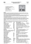
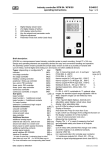
Industry controller type 902 / 93
Technical data
Characteristics: (parameters dep. on sub type:)
Adjustment on parameter level, code locked,
pre adjusted on customer´s demand.
Proportional band Xp: 0,1...999,9 %
Integral action time Tn: 0,0...999,9 min
Rate time Tv: 0,0...99,9 min
Sensitivity of response Xsh: 0,1...1,0 %
Travel time of the actuator Tm: 6...600 sec
Switching frequency cy: 2...120 sec
Function characteristics: direct / inverted
Switching interval SA (add. contacts): 0..100,0 K
Switching difference Sd: 0,1...100,0 K
Additional contact functions:
As switching interval above and below setpoint or
independent adjustable with own setpoint and
measuring input, switching function adjustable
(ref. to chapter additional switching contacts)
Installation dimensions:
B 902 E
- Page 2 of 2 -
stage controller (inverted)
K2
on
off
K1
Sd2
Sd1
SA2
actual value
SP
three- point- step- controller (inverted)
K1(+)
on
K2(-)
off
actual value
Sh
SP
continuous controller
single output
double output
100%
AP
0%
in..
di..
in
di
P
-100%
Y1
Y2
P1
SP
td td
SP
P2
..di
..in
l92-d4990419
Other data:
Housing for panel mounting, 96 x 96 mm
Power supply: 100..250 VAC, about 14 VA
alternative 24 V AC / DC
B +0,8
Protective system EN 60529: IP54 (terminals IP20)
+0,8
H
Permissible ambient temperature: 0...60°C
Nominal temperature: 20°C
Climatic category: KWF to EN 60529
Relative humidity <= 75 % yearly average,
Form 96x96: L=150mm, B=92mm, H=92mm
no condensation
EMC: referring to EN 61326
Wiring diagram: (Example, valid for each delivered controller is the wiring diagram on its casing only)
L
SPE
analog-, m easuring inputs
a99 +18V
a11
a1
*
a12
a
s
a2
a13 (-)
e
a3 (-)
ai1 a14 I
a4 I
a15 U
a5 U
a99 +18V
a99 +18V
a16
a6
*
a17
a
s
a7
a18 (-)
e
a8
ai2 a19 I
a9 I
a20 U
a10 U
SPE* a99 +18V
a0 (-)
a21
a22
(with Konf. SPE the
a23 (-)
Pt100 input of ai2 is
a24 I
additionally usable!) a25 U
a99 +18V
*= option
a26
a27
service
a28 (-)
interface
a29 I
KFM 2.0
a30 U
a
s
e
a
s
e
a
s
e
a
s
e
binary inputs
b99 (+) 24VDC
b0 (-) 0V
ai3 b1 Bin.1
b2 Bin.2
b3 Bin.3
b4 Bin.4
*
b5 Bin.5
b6 Bin.6
ai4 b7 Bin.7
b8 Bin.8
b9 Bin.9
b10 Bin.10
*
:
:
:
:
ai5 :
:
b17 Bin.17
b18 Bin.18
b19 Bin.19
*
b20 Bin.20
*
b0
b0
b21
b22
b23
b24
b25
b26
b27
b28
b29
b30
:
:
:
b37
b38
b39
b40
(-) 0V
(-) 0V
Bin.21
Bin.22
Bin.23
Bin.24
Bin.25
Bin.26
Bin.27
Bin.28
Bin.29
Bin.30
:
:
:
Bin.37
Bin.38
Bin.39
Bin.40
anal.-, logic outp. pow er supply, relays
35 (+) 0/24V
27 L+ (100..250V-type:
36 (-) logic out 1 28 L- internal fuse
37 (+) 0/24V
29
T 0,5 A )
36 (-) logic out 2 50a
62
38 (+) 0/24V
50
63
K5
K1 #
36 (-) logic out 3 51
64
30 (+) 0/4..20mA 52
65
31 (-) Y1
53a
66
K6
32 (+) 0/4..20mA 53
67
K2 #
31 (-) Y2
54
68
40 (+) 0/4..20mA 55
69
K7
31 (-) Sout 1
56a
70
41 (+) 0/4..20mA 56
71
K3 #
31 (-) Sout 2
57
72
K8
42 (+) 0/4..20mA 58
73
31 (-) Sout 3
59
74
43 (+) 0/4..20mA 60
K4
75
K9
31 (-) Sout 4
61
76
(Protect relay outp. by ext. fuse 2A)
ai6 with 2 binary input cards the
terminals b0 of each card
are linked (factory setting)
Optionally, RC element selective
connectable, see below,
N.O. contact factory-connected
#
Wiring, examples for input 1 and output 1 respectively:
Pt100
a1
a2 3-w ire
a3
a1
a2 2-w ire
a3
data subjects to alteration
standard signal
(-) a3
0/4..20mA
(+) a4
(-) a4 4..20mA
(+) a99 2-w ire-Tr.
(-) a3
0/2..10V
(+) a5
others
a1 thermoa2 couple
a
s
e
binary inputs
b99 pot.free
b1 contact
+
a1
feedback a2
device
a3
relay contact
actuator
50a w ithout RCup
50 element
50a N.O. contact
M
b1 external
50 w ith RC
dn
b0 voltage. 24V
50a N.C. contact
N
L
51 w ith RC
#
50a
50
51
52
53a
53
54
55
902_re.doc / 1110301