1
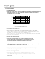
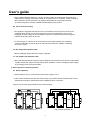
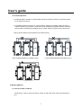
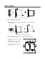
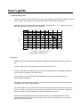
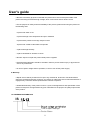
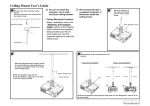
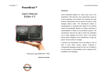
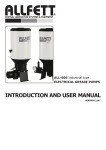
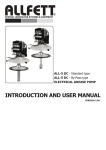
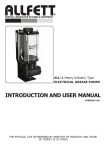
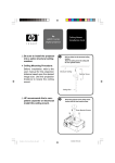
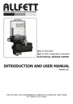
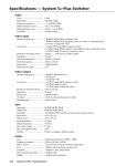
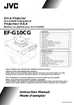
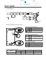
User's guide
1. BLOCK DIAGRAM
OUTPUT
INPUT
+V
L
LINE
FILTER
N
INRUSH
CURRENT
LIMIT
RECTIFIER
CIRCUIT
P.F.C.
CIRCUIT
+V
SWITCHING
DEVICE
RECTIFIER
CIRCUIT
CURRENT
DETECT
-V
-V
FG
ERROR
AMP
PWM
CONTROL
CIRCUIT
OVP
DETECT
OUTPUT
DETECT
(Green LED)
DC OK
DC LOW
(Red LED)
2. Terminal Pin Assignment and Front Controls
TB1 : Input Terminal Assignment
Marking No.
Assignment
TB2
1 2 3 4
++--
L
①
AC(L) Input Terminals
N
②
AC(N) Input Terminals
③
AC Grounding Terminal
V-ADJ.
DC OK
TB2 : Output Terminal Assignment
Marking No.
Assignment
V-ADJ.
DC LOW
DC OK
DC LOW
LN
+
②
-
③
-
④
DC (+) Output Terminals
DC (-) Output Terminals
V-ADJ. DC Output voltage adjustment trimmer
1 2 3
DC OK DC Output indication LED (Green)
TB1
DC LOW DC Output Low indication LED (Red)
3. Connection / Connecting Cable
Solid or Strsnded Wires
Terminals
[AWG]
[㎟]
Input Terminals(TB1)
0.5 ~ 2.5
30 ~ 12
0.5 ~ 2.5
①
Front Controls Assignment
Marking
Assignment
L N
Output Terminals(TB2)
+
30 ~ 12
2
Torque
Stripping length
[Nm]
L [mm]
0.5~0.6
8
0.5~0.6
8
User's guide
4. Function Explanation
4-1. Input voltage range
o Rated input voltage is at AC 100V through 240V (50/60Hz), while it is operational at AC 90V
through 264V (47~63Hz) or DC 120V through 370V. Please refer to Derating Curve at Figure 1
for output load factor by input voltage.
100
LOAD [ %]
80
50
20
90
100
145
175
205
235
264
INPUT VOLTAGE [VAC] 60Hz
< Fig1. Input Voltage Derating Curve >
4-2. Adjustable output voltage range
o Output voltage can be adjusted within ±10% range of rated output voltage by VADJ variable
resistance inside of the product, however, malfunction or over voltage protection feature can be
operational in case where output voltage exceeds the adjustable range.
Output current should be used under rated current in case output voltage is fixed over rated voltage.
ex) Vout=28V, I=8.57A (240W/28V)
4-3. O.C.P : Over Current Protection
o Over current protection circuit is to be in operation to cut off the output in order
to protect SMPS if output current exceeds over 110% of rated output current due
to malfunction of application system or short-circuit of external connection.
o Ourput current is limited and output voltage shuts off at 110% from the rated current in case output
current slowly increases during O.C.P operated. O.C.P by hic-cup method operates in case output
current rapidly increases or ourput terminal is short-circuited.
o Over current protection is to automatically restore the system once short-circuit of output
terminal or over current stage is resolved.
4-4. O.V.P : Over Voltage Protection
o Over voltage protection circuit is to be in operation to cut off the output in order to
protect SMPS if output voltage exceeds over 115% of rated output voltage or reversal
voltage occurs.
3
User's guide
o Over voltage protection feature is to be off, once the system is restored after the problem for
malfunction is resolved, followed by cutting off AC input power for 3 minutes. If output voltage is
NOT restored to normal, however, it is highly recommended to consult with personnel
at customer support to monitor possible internal damage to the product.
4-5. Inrush Current Limiting
o This product is equipped with built-in inrush current limiting circuit to protect circuitry from
damages due to inrush current when the power is turned on. Malfunction can occur by
repeating the input voltage on and off rapidly. Therefore, sufficient interval should be given
between turning the power on and off.
o In case a switch or a fuse is to be connected to input terminal (outside of the product),
careful consideration should be given at selecting the parts that is capable of enduring
the inrush current.
4-6. DC Output OK Indication LED
o DC OK LED light will be ON when properly operated.
4-7. DC Output Low Indication LED
o DC LOW LED light will be ON when output voltage is below 85%%(±2.5%) from the rated output
voltage. Please use it after removing factors which would be a cause of dropping output voltage
by checking product and load condition.
5. Series operation / Parallel operation
5-1. Series Operation
o Series operation can be connected as shown both at Figure 2 or 3.
o Load current should be less than the current value of the product with the lowest output current
specified at the product specification with the SMPS at series connection.
Note) A picture below may be different from actual product.
++--
++--
++--
++--
V-ADJ.
V-ADJ.
V-ADJ.
V-ADJ.
DC OK
DC OK
DC OK
DC OK
DC LOW
DC LOW
DC LOW
DC LOW
LOAD
LOAD
L N
L N
L N
< Fig.2 Series Operation A >
L N
< Fig.3 Series Operation B >
4
LOAD
User's guide
5-2. Parallel Operation
o Parallel operation should be composed with the same products, while the connection should
be as shown as Figure 6
o In parallel operation A at Figure 6, current capacity cannot be increased, while it should be
used for backup only. Moreover, diode that is to be added during parallel operation should be
selected after considering its voltage drop (Vf), output voltage (Vo) and current capacity (Io).
Note) A picture below may be different from actual product.
++--
++--
++--
++--
V-ADJ.
V-ADJ.
V-ADJ.
V-ADJ.
DC OK
DC OK
DC OK
DC OK
DC LOW
DC LOW
DC LOW
DC LOW
LOAD
L N
LOAD
L N
L N
< Fig.4 Parallel Operation A (Unable to use) >
++--
L N
< Fig.5 Parallel Operation B (Unable to use) >
++-V-ADJ.
V-ADJ.
DC OK
DC OK
DC LOW
DC LOW
LOAD
L N
L N
< Fig.6 Back-up >
6. Mounting Method
6-1. How to fix IS15 on DIN-rail
o Firstly hang A part on the top of Rail as shown on Fig.7 then Push IS15 into B direction to
fix it.
5
User's guide
A
B
< Fig.7 How to fix IS15 on DIN-rail >
6-2. How to remove IS15 from DIN-rail
o Remove IS15 to D direction pulling C part by using tools such as a screwdriver to
downward direction.
L N
D
C
< Fig.8 How to remove IS15 from DIN-rail >
6-3. IS15 should be mounted as follow in the consideration of air cooling
o Mounting method should be considered
with airflow.
Air
o Leave enough spaces between units
when several units mounted togather
15mm
or more
25mm
or more
o Forced air cooling makes protection
against heat better
Air
25mm
or more
< Fig.9 Mounting method >
6
User's guide
7. Output derating curve
o When the product is being used after normal mounting method is implemented, it should be used as
shown at Figure 10 according to room temperature with a consideration of output load.
Note) When using the product with room temperature at between -25℃ ~ 0℃, please keep in mind
that output ripple & noise could exceed its standard.
100
LOAD [%]
80
50
20
-25
0
10
60
30
40
50
20
AMBIENT TEMPERATURE [℃]
70
80
< Fig.10 Output Derating Curve >
8. Cautions
o Please confirm if the capacity of the product is suitable for your intended use before putting it in
use.
o Only the rated input voltage specified on the product should be used.
o Only the wires with rated capacity should be connected to this product, as allowable voltage and
current is varied according to each type of wire.
o Ground terminal of this product must be grounded before use to prevent electric shock or
electromagnetic interference.
o Be cautious to keep the product clean as foreign subject near input & output terminal or inside of
the product could cause serious damages.
o If a fuse installed in the product blows off, the product should experience damages not only to
the fuse but also to other parts as well; therefore, the product is to be required for maintenance
work from customer service department as well as replacement of the fuse.
o Because constant leakage current flows within the product, extra caution should be made if
multiple number of products are used connecting to each other as total leakage current could be
amounted beyond the capacity.
7
User's guide
o Be sure to avoid any physical contact with the product since some of the parts inside of the
product are being functioned at high voltage, which could cause serious electric shock.
o For the purpose of safety as well as reliability of the product, please avoid using the product at
the following sites:
- A place near water or fire
- A place with high room temperature and poor ventilation
- A place with a presence of foreign subject or dust
- A place near volatile or flammable compounds
- A place with high humidity
- A place vulnerable for vibration or shock
o Do NOT inspect or repair the product while power is applied.
o Unauthorized modification should be avoided in order to prevent serious injury or physical loss
due to any malfunction.
o In case of power outage while in operation, be sure to turn off the power supply.
9. Warranty
o Repair service will be provided for free upon any mechanical, technical or functional defects
during the guaranteed warranty, however, any defects or malfunction due to intentional infliction or
negligence by customers will be repaired at the customer’s expense.
o Guaranteed warranty of the product runs for 3 years, while appearance and specification of the
product is subject for change without any prior notification for the purpose of quality improvement
of the product.
10. ORDERING INFORMATION
IS
Total output wattage
Series Name
8