1
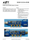
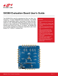
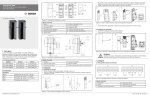
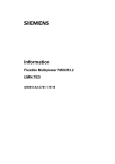
Si50x-FPB1-CUST F IELD P ROGRAMMER U SER ’ S G U ID E Description Features The Silicon Laboratories Si50x-FPB1-CUST kit contains the hardware and software needed for field programming the Si501/2/3/4 Singe/Dual/Quad/AnyFrequency single-wire programmable CMEMS® (CMOS + MEMS) oscillators. The Field Programmer Board (FPB) can be run on a USB-equipped PC. Field programming of Silicon Laboratories' Si501/2/ 3/4 CMEMS oscillators Windows-compatible software control and device programming Field Programmer Software 50X – BlankPart 501 – anyconfiguration 502 – anyconfiguration 503 – anyconfiguration Si50X ProgrammerBoard 504 – anyconfiguration Rev. 0.3 2/14 Copyright © 2014 by Silicon Laboratories Si50x-FPB1-CUST Si50x-FPB1-CUST 1. Quick Start 1. Install the Si50x CMEMS® FPB Software and driver. 2. Download FPB GUI Software from www.silabs.com/Si50x-FPB1 3. Launch the Field Programmable Oscillator Software by selecting Start All Programs Silicon Laboratories Si50x Field Programmer. 4. Install blank Device Under Test (DUT) to be programmed and follow the Graphical User Interface (GUI) directions. 2. Introduction This Si50x-FPB1 User’s Guide documents immediately useful information for programming blank devices (DUTs) and additional reference details in support of the Si50x-FPB1(FPB). This document also describes the operation of the Silicon Laboratories Si50x-FPB1 field programmer kit. The Si50x-FPB1 kit refers to the field programmer board hardware and software intended for field programming of the Si501, 502, 503, and 504 CMEMS oscillators. The term, “field programming” as it is used in this document refers to writing the write-once configuration registers in Non-Volatile Memory (NVM). The NVM controls the configuration of the device on powerup. 2.1. Kit Contents The Si50x-FPB1 kit contains the following: Si50x Field Programmer Board USB Type B retractable cable 5 blank 2025 parts 5 blank 2532 parts 5 blank 3250 parts Note: The FPB GUI must be downloaded from www.silabs.com/Si50x-FPB1. It is not included in the FPB Kit. The software components run on a USB-equipped PC and are described in detail in Section “11. Software Guide” The Si50x-FPB1 field programmer board can be used to program one Si50x CMEMS oscillator at a time when installed in 1 of 4 differently sized sockets. 2 Rev. 0.3 Si50x-FPB1-CUST 2.2. FPB-EVB GUI Quick Start Guide TypeanexistingOPNhereandallexisting OPNsdisplaybelow.Hit<enter>to deployOPNconfigurationintooption dropͲdownboxes. Hitmagnifyingglasstoseealistofall OPNsgeneratedbytheuser’sFPB. Option1:Vdd,lowpower/lowjitter,tr/tf Selectdevice:Si501/Si502/Si503/Si504. Theavailableoptionschangeaccording totheselecteddevice. Createreportonlygeneratesthereport anddoesnotprogramanysample.Thisis availablewithorwithoutanFPBboard. Packageselectioncorrespondstoa specificsocketshownbylightedLED. Programthetargetdevice,generatean OPNandreport.Usermusthavea SiLabs.comuserIDandbeconnectedto theinternet.UserDOESNOThavetobe connectedtoprogramthepartand report,butanOPNwillnotbegenerated. Revisionisnotselectablebecausethere isonlyRevA. “PartNumber”willdisplay“XXXX”until anofficialOPNisavailable.IfanOPNis available,thisfieldwilldisplaythefull OPN. ProvidestheOPNandreport.Doesnot programapart.Usermusthavea SiLabs.comuserIDandbeconnectedto theinternet. Greencheckindicatesboardis connected. Clearsform. Figure 1. Main Screen (1 of 2) Rev. 0.3 3 Si50x-FPB1-CUST Select“BuyMoreBlankParts”tobuy moreblankstocreatemoresamples. Clickthelinktobuytheasmanyblanks asneededinthedesiredpackage. Figure 2. Buy More Blank Parts Screen 4 Rev. 0.3 Si50x-FPB1-CUST RightClickintheSearchfieldtoselect whetheryouseeALLOPNsinSAPorjust theOPNscreatedonthisField ProgrammerBoard. Figure 3. Main Screen (2 of 2) Rev. 0.3 5 Si50x-FPB1-CUST LEDindicatestargetsocketfor programming.Anerrormessagewill displayifthedeviceisinadifferent socketthantheonetargeted. Returnstomainscreen.Allsettings remain. Redasterisk=requiredinformation Figure 4. Programming Screen 6 Rev. 0.3 Si50x-FPB1-CUST Table 1. Drop Down Menus Drop Down Menu Selection Function Options Exit Exits GUI. Tools Advanced Control Programmer Board Allows user to enable/disable VDD and set OE High/OE Low. This is an advanced feature. Advanced Update FW Updates EVB FW with file saved to hard drive. New FW is included any time the GUI is updated. Submit Pending OPNs If a user has created part configurations while not connected to the internet, they will be stored here. The GUI will also prompt the user to submit pending OPNs at launch. Generate OPN Initiates the process to generate an OPN. Query FPB FW Version Provides FPB MCU Firmware version. View Latest Sample Report Opens last generated report. View Part Number History Opens a table of all part numbers generated by the FPB. The report can be exported to Excel. View All Sample Reports on Hard Drive Opens the directory where all sample reports are stored. EVB Firmware Version Provides the EVB FW version number. User’s Guide Opens the User’s Guide in pdf. Device Data Sheet Opens latest device data sheet. Later revisions of the data sheet are loaded with new GUI SW updates. Order Blank Parts Provides the OPN for more blank parts. More parts must be ordered through Silicon Labs representatives. Check for GUI Software Update Checks www.silabs.com for any available GUI updates. Check for FPB Firmware Update Checks www.silabs.com for any available FW updates for the FPB MCU. About Provides information on FPB SW and FW version numbers. Order more blank parts Order more blanks samples in whatever package size is required. Reports Help Buy More Blank Parts Rev. 0.3 7 Si50x-FPB1-CUST 3. Board Views 3.1. Top Board View Figure 5. Top Board View 8 Rev. 0.3 Si50x-FPB1-CUST 3.2. Bottom Board View Figure 6. Bottom Board View Rev. 0.3 9 Si50x-FPB1-CUST 4. Functional Description Figure 7. Block Diagram The pages that follow provide the detailed functional description of the hardware. The FPB schematics, bill of materials, and PCB layouts are included as sections 15, 16, and 17, respectively. Figure 7 provides a block diagram for the board. Location descriptions in this document assume the reader is viewing the board in the conventional orientation, i.e., looking down on the top side (primary side) with the silkscreen text right side up as in Figure 5. 4.1. Power Supply The Si50x-FPB1 is pre-configured to accept +5 V from the USB connector at J1. The +5 V is filtered and routed to the MCU, the DUT VDD voltage regulator, and to each DUT’s status LEDs. The output of the voltage regulator is under MCU control and yields either 3.3 V or 4.1 V. The higher voltage is used when writing to the DUT’s NVM. The power supply components are mounted on the back side of the board 10 Rev. 0.3 Si50x-FPB1-CUST 4.2. MCU The Silicon Laboratories MCU, P/N C8051F380 is also mounted on the back side of the board at U 2. The MCU provides the following functions: Supports single-wire communication (C1) to the DUT on behalf of the host PC per the Field Programmable Oscillator Software Drives 3-state status indicator LEDs (see Table 3) Supplies 3.3 V to peripheral ICs (the serial number generator and the C1 voltage level shifter) Controls DUT voltage supply regulator (see Section “4.1. Power Supply” ) Switches in pull-down near end bias resistors (reserved for future use) Auto-detects the board type. The firmware identifies the board type MCU via port P1.7 (pin 29). The voltage at this pin is pulled up internally on the Si50x-FPB1. (The pin is pulled down via an external resistor on the Si501/ 2/3/4-EVB customer evaluation board.) Rev. 0.3 11 Si50x-FPB1-CUST 5. Device Support The FPB has four latch-able sockets installed to support four different surface mount package sizes. These are enclosed in red in Figure 8 below. To the right of each socket is the corresponding device footprint to further guide the user as to which socket supports which size package. Note that the pin 1 location is marked in silk screen beside each package footprint. The device must be inserted into the socket in this orientation to work. Also note that some landing patterns have six pads. This is to support future differential output devices. The Si501/2/3/4 have four pins and only support single-ended LVCMOS outputs. Figure 8. Socket Locations Reference information regarding sockets and package compatibility is listed in Table 2 below. Sockets are listed in the same relative order as shown in Figure 8. Table 2. Si50x-FPB1 Device Support 12 Nominal Package Size (mm) Socket Ref Des # Pins Supported Devices 2x2.5 U12 4 2.5x3.2 U11 6 Si501, Si502 Si503, Si504 3.2x4 U10 5x7 U6 N/A Rev. 0.3 Notes Reserved Si50x-FPB1-CUST 6. USB A 4-pin USB Type B receptacle is provided at location J1. The Si50x-FB1 is compatible with USB Specification 2.0. This connector is mounted on the back of the PC board in the lower left hand corner. The location is noted on the top side with silkscreen artwork showing an icon of a PC with bidirectional arrows. See Figure 9 below. Figure 9. USB Connection Location Rev. 0.3 13 Si50x-FPB1-CUST 7. Status Signals The five LEDs on the board are listed in Table 3. Four of these are surface mount tri-color Red, Green, Blue (RGB) LED units that report the programming status for DUTs in their respective sockets. (Note that yellow or amber is produced by mixing Red + Green light simultaneously). The location of these LEDS is noted in Figure 10. Table 3. Si501-FPB1 LEDs Ref Des Signal Color (Status) Notes D2 Ready Green Should illuminate on USB connection (power up) U4 5x7 Status Reserved U7 3.2x4 Status U8 2.5x3.2 Status Green (Pass) Red (Fail) Yellow (Busy) Blue (Socket Location) U9 2x2.5 Status Figure 10. Si501-FPB1 LEDs 14 Rev. 0.3 Si50x-FPB1-CUST 8. Current Sense Resistor There is one current sense resistor located on the FPB designated R7 and placed between test points VDD_DUT_PIN TP15 and VDD_DUT TP16 in the center back side of the board. R7 is pointed out in the photo below. The default or pre-loaded resistor value is 2 . The voltage drop across this resistor may be used for calculating a DUT's current draw and power consumption. Figure 11. Current Sense Resistor Location Rev. 0.3 15 Si50x-FPB1-CUST 9. Outputs At this time, the Si50x-FPB1 supports only single-ended format outputs on the Si501/2/3/4 CMEMS oscillator. The three 6-pin sockets will support differential outputs on future oscillator devices. Near-end bias resistors are installed to support future devices. All outputs are ac-coupled to test points on the right hand side edge of the board (see Figure 12). These output test points are also included in Table 4. Figure 12. Output Test Points 16 Rev. 0.3 Si50x-FPB1-CUST 10. Headers and Test Points For reference purposes, all headers (JP*) and test points (TP*) are collected in Table 4. There are no headers intended for routine jumper use in the current version of the FPB. The output test points give ac-coupled access to a DUT installed in a socket. Generally, these test points are not populated. (The “NI” in the Notes column means “Not Installed”.) Table 4. Si50x-FPB1 Headers and Testpoints Category Ref Des Signal Notes MCU JP1 1-C2D Header 4x1 2-C2CLK 3-BOOTLDR 4-GND Power Supplies Outputs TP1 3.3V Red Loop TP11 GND Black Loop TP12 GND Black Loop TP15 VDD_DUT_PIN Red Loop TP16 VDD_DUT Red Loop TP17 5x7 CLKN NI TP18 5x7 CLKP NI TP19 5x7 GND NI TP20 3.2x4 CLK_N NI TP21 2.5x3.2 CLKN NI TP22 3.2x4 CLKP NI TP23 2.5x3.2 CLKP NI TP24 2x2.5 CLK NI TP25 3.2x4 GND NI TP26 2.5x3.2 GND NI TP27 2x2.5 GND NI Rev. 0.3 17 Si50x-FPB1-CUST 11. Software Guide Users must download the Si50x CMEMS Oscillator Software, available from the Silicon Labs website at www.silabs.com/Si50x-FPB1. This software includes a User's Guide as well. The FPB SW controls the FPB and allows the user to set all configurable parameters, program devices, and generate orderable part numbers and reports. 11.1. Configuring the Si501-FPB1 Figure 13. Si50x-FBP1 Typical Configuration 18 Rev. 0.3 Si50x-FPB1-CUST 11.2. 50X Field Programmer Software Installation The following sections describe how to install and use the 50X Field Programmer software. This software runs on a USB equipped PC to field program the NVM of Si501/2/3/4 MEMS oscillators. It can also be used to generate an OPN (Orderable Part Number). Context sensitive help windows pop up when the cursor hovers above a feature on the GUI. There is a readme.txt file with the installation files as well as a software user guide installed with the software. System Requirements Microsoft Windows® 2000, XP, Vista, 7 USB 2.0 MB of free hard drive space 1024 x 768 screen resolution or greater Microsoft .NET Framework 4.0 USBXpress 3.1.1 driver 2 Note: USBXpress 3.1.1 driver is provided and installed with the software. 11.3. Microsoft .NET Framework Installation The Microsoft .NET Framework is required before installing and running the software. Details and installation information about the .NET Framework are available via a shortcut in the NETFramework directory or at the following web site: http://www.microsoft.com/en-us/download/details.aspx?id=26 There are multiple versions of the .NET Framework available from Microsoft, and they can be installed side-by-side on the same computer. The software requires Version 4.0. Contact your system administrator for more details. 11.4. Si50x CMEMS® Field Programmer Oscillator Software Installation The Si50x CMEMS Oscillator Software is installed from the Si50xCMEMSSwInstall.exe file. 1. Double-click the install file to start the wizard. 2. Follow the wizard instructions to complete the installation for both the software and the driver. Use the default installation location for best results. 3. After the installation is complete, click on Start Programs Silicon Laboratories Si50x CMEMS Oscillator Software. Select one of the items in the menu including the User Guide to get more details on how to run the software. Rev. 0.3 19 Si50x-FPB1-CUST 12. Si50x CMEMS® Field Programmer Oscillator Software Overview The FPB software supports specifying a configuration and then creating a sample or generating an Orderable Part Number or OPN. The main menus appear at the top as shown in the red rounded rectangle in the GUI excerpt below. The top level menus and their pull-down functions are listed in Table 1, “Drop Down Menus,” on page 7. 20 Rev. 0.3 Si50x-FPB1-CUST 13. Basic Operating Instructions Basic operating instructions are illustrated in the following section based on a step by step example session. 1. Connect the Field Programmer Board by USB Once the GUI software is installed, the Field Programmer Board must be connected to any available USB port on the PC hosting the GUI software. If the USB connection is broken or not functional, a red indicator on the GUI will be displayed. The top banner of the window will also indicate “no programmer found”. If this error occurs unexpectedly, verify that your USB port is operational and/or the GUI software and USB driver is properly installed. Rev. 0.3 21 Si50x-FPB1-CUST When the USB connection is operating, the indicator turns green and a green “Ready” LED will illuminate on the Field Programmer Board. We can now move on to selecting the target device and options. 22 Rev. 0.3 Si50x-FPB1-CUST 2. Select Device Type It is recommended that option parameters are selected starting from the top with “Device Type” and proceeding sequentially downward. Pull down selections are available for most options. In this example, we select the Si503 as our target device. The Si503 allows for the selection of four programmed frequencies controlled by external pullup and pull-down resistors at the FS/OE pin. Rev. 0.3 23 Si50x-FPB1-CUST 3. Select VDD, Jitter/Power, and Rise/Fall Time Options VDD, Jitter, Power Mode, and Rise/Fall Time (tRise/Fall) options are shown in the pull down menu. The Si501 family supports a low period jitter option that consumes slightly more power (about 1 to 2 mA) or a low-power option that results in slightly more period jitter (about 1 to ½ ps rms). Selecting the right tRise/Fall is a key benefit of the Si501 family as you can easily drop-in to competitive sockets by matching their existing drive strength. For this example, Lower Jitter with 0.7 ns rise/fall time options are selected, which is option “H”. 24 Rev. 0.3 Si50x-FPB1-CUST 4. Select Frequency Stability The Si501 frequency stability is guaranteed for 10 years of operating life. In this example, a frequency stability of ±20 ppm is selected. Rev. 0.3 25 Si50x-FPB1-CUST 5. Select Internal Resistor Device default functionality is set to Run, Sleep, Doze, etc., according to a configurable OE selection. The internal OE pull-up is selected for this example. Refer to the device data sheet for more details on the use and external termination options of the multi-function OE pin. 26 Rev. 0.3 Si50x-FPB1-CUST Note that the appearance of the GUI will change based upon the device selection. Had we selected a comparable version Si502 (the dual frequency counterpart), the window would appear as follows. In this case, the Internal Resistor selection has been replaced by the OE High | OE Wk High | OE Low | Int. Resistor selection. As the data sheet explains, if the pull-up resistor is < 2 k, it is a strong pull-up resistor resulting in a “Strong High” and abbreviated in the GUI simply as OE High. If the pull-up resistor is > 16 k, it is a weak pull-up resistor, resulting in a “Weak High” at the OE pin. The OE Internal Pull-up resistor is nominal 50 k which is a “Weak High” resistor value. Therefore, the default frequency selection for OE Wk High is Freq 2. In the example above, pulling the OE pin low results in the Stop condition which means the output is disabled and the internal oscillator is set to FCLK = 1 MHz. Rev. 0.3 27 Si50x-FPB1-CUST 6. Specify Output Frequencies Since the Si503 is a four frequency device, each frequency must be specified. Output 1 is assigned a frequency of 32.768 kHz (for a clock timer application), output 2 to 12.288 MHz (for an audio clock application), output 3 to 24 MHz (for a USB application), and output 4 to 250 MHz. For the purposes of illustration, the last assignment is a purposefully introduced typo. The frequency should have been 25 MHz for a MCU application. Notice output frequency #4 is flagged. It is highlighted in red with a red graphic. If we hover the cursor over the red “x” graphic, we will see an explanation of the problem. The Si503 can support a maximum frequency of 100 MHz. The attempted 250 MHz assignment exceeds the limit and is therefore not supported. 28 Rev. 0.3 Si50x-FPB1-CUST When valid frequency selections are entered, we can proceed to the next option. At this point, if any option or parameter is not properly specified, the “Create Sample & Generate OPN” button is grayed-out and Sample Creation is not yet possible. We need to make a few more selections before programming can begin. Rev. 0.3 29 Si50x-FPB1-CUST 7. Select Package For package size, the 2.0 x 2.5 mm package is selected. Once this selection is made, a blue LED will illuminate on the Field Programmer Board next to the 2.0 x 2.5 mm socket. This LED serves to guide the installation of the blank part into the proper socket. Make sure you carefully install a blank part in the appropriate indicated socket and ensure all other sockets are empty. 30 Rev. 0.3 Si50x-FPB1-CUST 8. Select Operating Temperature The final selection is the operating temperature range. In this example, the industrial temp range of –40 to +85 °C is selected. Rev. 0.3 31 Si50x-FPB1-CUST 9. Create a Sample Once all options and parameters have been entered and validated, the “Create Sample & Generate OPN” button is now active. Press the “Create Sample & Generate OPN” button to start the programming process. “CreateSample”, “CreateReport”, and“Generate OPN”buttonsare nowactive indicatingall parametersare valid. 32 Rev. 0.3 Si50x-FPB1-CUST 10. Place Blank Part in Socket At this point, place a blank part into the socket indicated by the blue LED and then press the “Confirm” button to proceed. Note:Before programmingis started,make surethesocket indicatedbythe blueLEDis properlyloaded withadevice. Usermayenter commentshere. Theywillbe printedonthe OPNreport. Rev. 0.3 33 Si50x-FPB1-CUST The Field Programmer will first check to make sure a blank part is installed in a socket. 34 Rev. 0.3 Si50x-FPB1-CUST 11. Connect to Silicon Labs Once a blank part has been verified, the Field Programmer GUI software will check for an internet connection to Silicon Labs. If a connection has been made, but the user has not previously logged-in, log-in credentials will be required. For new users, select the “Create Your Profile” button and follow the directions. Once properly logged-in, programming will continue. If no connection, or log-in is unsuccessful, you can select “Cancel OPN Generation”. If a previous login connection is still active, this page will be skipped altogether. Rev. 0.3 35 Si50x-FPB1-CUST 12. Checking and Report Generation Once connection to Silicon Labs has been established, the device will be programmed and a programming report will be created. 36 Rev. 0.3 Si50x-FPB1-CUST 13. Programming Complete The CMEMS oscillator has been successfully programmed. A sample device and an orderable part number has been created. It is now safe to remove the programmed part from the socket. Note that, once a part is programmed, it cannot be changed or re-programmed. Each CMEMS part stores its configuration in on-chip, One-Time Programmable (or OTP) memory. Select “View Report” to see a report of the programmed device. The report gives a record of the part and the corresponding OPN. Select “Create Another” to create another sample with the same part number or select “Back” to return to the main page or start page. From the start page, you can select pulldown menu Reports and then directly select any of these options: View Latest Sample Report View Part Number History View All Sample Reports on Hard Drive Rev. 0.3 37 Si50x-FPB1-CUST In the future, you can select the Back button and then search for the existing part number in the Enter Part Number field. 38 Rev. 0.3 Si50x-FPB1-CUST Part numbers representing the programmer’s history will be listed as in the figure below. You can then double-click on the row to select a particular part number such as 501AAA15M0000BAF, which has been generated in the example. All fields are populated with that part number’s information on the start page and a part sample of your selection can be created as previously shown. To exit the application, go back to the start page and select the pull down menu Options Exit. Rev. 0.3 39 Si50x-FPB1-CUST 14. Help Help is available in various forms. “Hovering” the cursor over an entry or image on the start page, for example, will yield a brief explanation in context. For an example of this “hover help”, please see the figure below. In this case, the cursor was placed over the board image in the lower left hand corner, which triggered an information window containing the board serial number and F/W and S/W revisions. 40 Rev. 0.3 Si50x-FPB1-CUST Additional help is available by selecting the Help pulldown menu and then selecting one of the options listed as illustrated below. Note that retrieval of the latest version of the User’s Guide (this document) and Device Datasheet will require internet access. Rev. 0.3 41 Si50x-FPB1-CUST 15. Tools There are a number of useful items available under the start page menu, Tools, as illustrated in the screen capture below. In this first example, Control Programmer Board has been selected. 42 Rev. 0.3 Si50x-FPB1-CUST Selecting Control Programmer Board yields the following useful page which gives the user control over the DUT’s VDD and the polarity of the Output Enable (OE) signal. The signal can be probed at the output test points to verify proper operation of the part. Rev. 0.3 43 Si50x-FPB1-CUST Another useful feature is to select Tools Check Device Orientation. If a single DUT is properly oriented in the socket, the GUI will report as follows. If not, then the FPB GUI will report one of several error messages as necessary depending on the situation: “Sockets are empty” “Device is inserted backwards” “Multiple sockets are populated with devices” 44 Rev. 0.3 Si50x-FPB1-CUST 14. Si50x CMEMS™ Field Programmer Oscillator Software Uninstall Close all the programs and help files before running the uninstaller to ensure complete removal of the software. To uninstall the software, use the Add and Remove Programs utility in the Control Panel or click Start All Programs Silicon Laboratories Si50x Field Programmer Uninstall Si50x Field Programmer. The EVB Driver (USBXpress®) software must be uninstalled separately via the host PC’s Control Panel. Locate and select the entry Silicon Laboratories USBXpress Device (Driver Removal) as in the figure below and click Uninstall / Change. Rev. 0.3 45 Si50x-FPB1-CUST 15. Schematics Figure 14. MCU & USB, Sheet 1 of 3 15.1. MCU & USB 46 Rev. 0.3 Si50x-FPB1-CUST Figure 15. Voltage Regulators, Sheet 2 of 3 15.2. Voltage Regulators Rev. 0.3 47 Si50x-FPB1-CUST Figure 16. DUT Sockets, Sheet 3 of 3 15.3. DUT Sockets 48 Rev. 0.3 Si50x-FPB1-CUST 16. Bill of Materials Table 5. Si50x-FPB Eval Board Bill of Materials Rev 1.0 NI Qty Reference Value 18 C1 C2 C4 C5 C7 C13 C14 C15 C16 C17 C18 C19 C20 C21 C22 C23 C24 C25 1 Rating Volt Tol Type PCB_Footprint ManufacturerPN Manufacturer 0.1 µF 10 V ±10% X7R C0402 C0402X7R100-104K Venkel C10 10 µF 25 V ±20% TANT C6032 T491C106M025ZT Kemet 1 C12 0.01 µF 10 V ±20% X7R C0402 C0402X7R100-103M Venkel 2 C3 C6 4.7 µF 10 V ±20% TANT C3216 TAJA475M010RNJ AVX 3 C8 C9 C11 1 µF 10 V ±10% X7R C0603 C0603X7R100-105K Venkel 2 D1 D3 MMBD3004S-7-F 225mA Dual SOT23-AKC MMBD3004S-7-F Diodes Inc. 1 D2 GREEN 25mA LED-0603 SML-LX0603SUGW LUMEX INC 1 FB1 22 6000mA SMT L0805 BLM21PG220SN1 MuRata 1 J1 USB Type B USB CONN-USB-B 292304-1 Tyco 4 MH2 MH3 MH4 MH5 SCREW/STANDOFF HDW NSS-4-4-01/2397 VARIOUS 6 Q1 Q2 Q3 Q4 Q5 Q6 BSS138 200mA 4 R1 R3 R5 R6 1K 1/16W 1 R10 15K 4 R11 R16 R17 R18 4 300 V 50 V N-CHNL SOT23-GSD BSS138 Diodes Inc. ±1% ThickFilm R0402 CR0402-16W-1001F Venkel 1/16W ±1% ThickFilm R0402 CR0402-16W-1502F Venkel 10K 1/16W ±1% ThickFilm R0402 CR0402-16W-1002F Venkel R12 R19 R20 R21 2K 1/16W ±1% ThickFilm R0402 CR0402-16W-2001F Venkel 4 R13 R22 R23 R24 4.99K 1/16W ±1% ThickFilm R0402 CR0402-16W-4991F Venkel 6 R14 R15 R25 R26 R27 R28 150 1/16W ±1% ThickFilm R0402 CR0402-16W-1500F Venkel 1 R2 499 1/16W ±1% ThickFilm R0402 CR0402-16W-4990F Venkel 1 R4 909 1/16W ±1% ThickFilm R0805 CR0402-16W-9090F Venkel 1 R7 2.0 2W ±1% ThickFilm R2512 CR2512-2W-2R00F Venkel 1 R8 47K 1/16W ±1% ThickFilm R0402 CR0402-16W-4702F Venkel 1 R9 39.2K 1/16W ±1% ThickFilm R0402 CR0402-16W-3922F Venkel Rev. 0.3 49 Si50x-FPB1-CUST Table 5. Si50x-FPB Eval Board Bill of Materials Rev 1.0 (Continued) NI Qty Reference Value 1 U1 DS2411 1 U10 3.2x4 mm, 6-Pin, Socket 1 U11 1 Rating Volt Tol Type PCB_Footprint ManufacturerPN Manufacturer SOJ6N4.45P1.27 DS2411P+ Maxim DFN DFN6N3.2X4-SKTSER AQ10001-P SER 2.5x3.2 mm, 6-Pin, Socket DFN DFN6N2.5X3.2-SKTSER AM0295-580R SER U12 2x2.5 mm, 4-Pin, Socket DFN DFN4N2X2.5-SKTSER AQ0015-520R SER 1 U13 5x7 mm-BLANK Si50X OSC6N7.0X5.0 501-PROG-AAX SiLabs 1 U14 3.2x4 mm-BLANK Si50X OSC6N3.2X4.0 501-PROG-BAX SiLabs 1 U15 2.5x3.2 mm-BLANK Si50X OSC6N3.2X2.5 501-PROG-CAX SiLabs 1 U16 2.0x2.5-BLANK Si50X OSC4N2.0X2.5 501-PROG-DAX SiLabs 1 U2 C8051F380 MCU QFP48N9X9P0.5 CF380-PX0746GQ SiLabs 1 U3 MAX8869 1A LDO TSSOP16N6.5P0.65 E MAX8869EUE50 Maxim 4 U4 U7 U8 U9 598-8610-307F 20 mA LED3-1210-KKKA 598-8610-307F Dialight 1 U5 SN74LVC1T45 SOT23-6N SN74LVC1T45DBV TI 1 U6 5X7mm, 6-Pin, Socket DFN DFN6N5X7-SKTSER AM0393-1300R SER Type PCB_Footprint ManufacturerPN Manufacturer 1.65– 5.5 V Not Installed Components NI Qty Reference Value NI 1 JP1 HEADER 4X1 Header CONN-1X4 TSW-104-07-T-S Samtec NI 14 TP1 TP15 TP16 TP17 TP18 TP19 TP20 TP21 TP22 TP23 TP24 TP25 TP26 TP27 RED Loop TESTPOINT 151-207-RC Kobiconn NI 2 TP11 TP12 BLACK Loop TESTPOINT 151-203-RC Kobiconn 50 Rating Volt Tol Rev. 0.3 Si50x-FPB1-CUST 17. Layout Figure 17. Primary Side Assembly Figure 18. Secondary Side Assembly Rev. 0.3 51 Si50x-FPB1-CUST Figure 19. Primary Side (Layer 1) Figure 20. Signal/Ground (Layer 2) 52 Rev. 0.3 Si50x-FPB1-CUST Figure 21. Ground (Layer 3) Figure 22. Secondary Side (Layer 4) Rev. 0.3 53 Si50x-FPB1-CUST 18. Fabrication Drawing 54 Rev. 0.3 Si50x-FPB1-CUST CONTACT INFORMATION Silicon Laboratories Inc. 400 West Cesar Chavez Austin, TX 78701 Tel: 1+(512) 416-8500 Fax: 1+(512) 416-9669 Toll Free: 1+(877) 444-3032 Please visit the Silicon Labs Technical Support web page: https://www.silabs.com/support/pages/contacttechnicalsupport.aspx and register to submit a technical support request. Patent Notice Silicon Labs invests in research and development to help our customers differentiate in the market with innovative low-power, small size, analogintensive mixed-signal solutions. Silicon Labs' extensive patent portfolio is a testament to our unique approach and world-class engineering team. The information in this document is believed to be accurate in all respects at the time of publication but is subject to change without notice. Silicon Laboratories assumes no responsibility for errors and omissions, and disclaims responsibility for any consequences resulting from the use of information included herein. Additionally, Silicon Laboratories assumes no responsibility for the functioning of undescribed features or parameters. Silicon Laboratories reserves the right to make changes without further notice. Silicon Laboratories makes no warranty, representation or guarantee regarding the suitability of its products for any particular purpose, nor does Silicon Laboratories assume any liability arising out of the application or use of any product or circuit, and specifically disclaims any and all liability, including without limitation consequential or incidental damages. Silicon Laboratories products are not designed, intended, or authorized for use in applications intended to support or sustain life, or for any other application in which the failure of the Silicon Laboratories product could create a situation where personal injury or death may occur. Should Buyer purchase or use Silicon Laboratories products for any such unintended or unauthorized application, Buyer shall indemnify and hold Silicon Laboratories harmless against all claims and damages. Silicon Laboratories and Silicon Labs are trademarks of Silicon Laboratories Inc. Other products or brandnames mentioned herein are trademarks or registered trademarks of their respective holders. Rev. 0.3 55