1
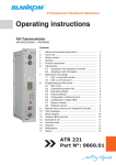
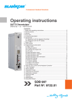
Professional Headend Solutions
Operating instructions
SAT-TV Transmodulator
DVB-S/ S2
→
DVB-C/ ITU-T J.83 Annex B, C
Contents
1. Safety and operating instructions................................................................... 2
2. Device variants ............................................................................................... 2
3. General ............................................................................................................. 2
4. Front view .......................................................................................................... 3
5. Functional description....................................................................................... 3
6. Adjustments ..................................................................................................... 3
6.1 Adjustment with the Headend Controller................................................... 3
6.2 Adjustment with PC/ laptop........................................................................ 3
6.2 Adjustment with SNMP............................................................................... 3
7. Meaning of status LED‘s................................................................................... 4
8. Programming by web server ............................................................................ 4
8.1 Main menu ............................................................................................... 4
8.2 Extended settings ...................................................................................... 5
8.3 Table processing ....................................................................................... 5
8.4 NIT entries ................................................................................................. 5
8.5 Configuration channel list-LCN ................................................................. 5
8.6 Program filter ............................................................................................. 6
8.7 Data rate overview ..................................................................................... 6
8.8 Device status.............................................................................................. 6
8.9 Software overview ..................................................................................... 7
8.10 Factory settings ....................................................................................... 7
9. Manual menu control with Headend Controller ............................................... 8
10. SNMP trap messages..................................................................................... 8
11. Block diagram ............................................................................................... 9
12. Head end bus structure.................................................................................. 9
13. Application example...................................................................................... 10
14. Technical data .............................................................................................. 11
15. Glossary......................................................................................................... 11
16. Bibliography ................................................................................................. 12
17. Document history ......................................................................................... 12
STB 016
Part No: 9710.02
STB
016
Part N : 9710.02
SAT-TV Transmodulator
DVB-S/ S2→DVB-C/ ITU-T J.83 Annex B, C
o
B
LINE
1. Safety and operating instructions
When assembling, starting-up and adjusting the modules, it is necessary to consider the system specific references in
the manual instruction.
The modules may only be installed and started up by authorized technical personnel.
When assembling the modules into the receiving points, the adherence of the EMC regulations is to be secured.
The assembly and wiring have to be done without voltage.
All active modules may only be operated with the Headend Controller HCB x00 or Bus Extender BEB x00.
The main voltage and the operating voltage of the modules working by DC have to be in complience to the operating
parameters described in the technical data.
With all work the defaults of the DIN EN 50083 have to be considered. Especially the safety relevant execution of the
DIN EN 60728-11[4] is necessary.
2. Device variants
STB 016
9710.02
DVB-S/ S2 → DVB-C/ ITU-T J.83 Annex B, C
Mininum software requirements for HCB x00:
9650.03:
9650.04/.05:
9652.01: 9653.01: 9653.02: version 2.34*
version 3.18*
version 3.23*
version 3.27*
version 3.28*
*) Updates: www.blankom.de
3. General
The SAT-TV transmodulator STB 016 is a module of the head end system B-LINE wich is conceived as a complete system for
middle-sized networks.The module converts one DVB-S/ S2 transponder into the digital cable standard DVB-C or ITU-T J.83 Annex
B or C. The signals will be transcoded into cable TV channels. All modules will be programmed via a central control unit (HCB x00)
and are working fully independent afterwards. The status of the modules are displayed via LED’s (see chapter 7 “Meaning of status
LED‘s“).
2
STB
016
Part N : 9710.02
SAT-TV Transmodulator
DVB-S/ S2→DVB-C/ ITU-T J.83 Annex B, C
o
B
LINE
4. Front view
SAT-TV TRANSMODULATOR
DVB-S/S2→DVB-C/ITU-T J.83 Annex B,C
Type: STB 016 Part No.: 9710.02
SAT-IF IN
INPUT LEVEL
TV-RF OUT
OUTPUT LEVEL
SUPPLY CURRENT
950 ... 2150
42 ... 82
45 ... 862
max. 116
0.9
SAT - IF
IN
SAT IF input
MHz
dBµV
MHz
dBµV
A
Operating voltage/
control bus
X1
LED “STANDBY“ (red)
LED “READY“ (green)
LED “ADDR.“ (yellow)
Address selector
RF output
5. Functional description
The SAT IF input signal is fed to the DVB-S/ -S2 front end, where the selection of a transponder and its QPSK or 8PSK demodulation
is done and a data stream is generated. All services of the resulting transport stream which shall be processed into the QAM modulator will be choosen by controling software of the module. The SI and PSI tables affected (i.e. the PAT, PMT, SDT, EIT) are automatically
corrected. The Headend Controller serves to generate an NIT (Network Information Table) into the transport stream. This is required
to enable the receiver (such as Set-Top-Box) to tune in automatically. The changed SI an PSI tables are fed into the QAM modulator
and an IF signal is generated at the output channel. There is a free choise of frequency in the output channel from 45 to 862 MHz.
On the output side, the modulator does not leak to adjacent channels. So that errors in level can be signalled if the load fluctuates
(the red LED will flash and a trap message will be sent), a reference level is generated. Every time the level for frequency figures are
programmed, automatic measurement of the refence level takes place; this function will, however, not start until 100 seconds have
elapsed after start-up of the system. This function can be enabled or disabled in the main menu.
6. Adjustments
6.1 Adjustment with the Headend Controller
· Adjustment of the addresses at the Bus Extender BEB x00 and at the modules
· Activation of the programming mode on each module by selecting the line (BEB x00) and the module position (01... 15) at the
Headend Controller (HCB x00) → yellow LED illuminates until the beginning of the parameter adjustment
· Adjustment of the STB 016 parameters (see chapter 9) → green LED is switched on
· After the programming the STB 016 will be automatically switched into the operating mode
→ yellow LED flashes shortly/ green LED is switched on
6.2 Adjustment with PC/ laptop
· Prerequisite for the remote programming is an “online-connection” acording the IP standard and an ethernet connection at the PC/ laptop
· Adjustment of the line/ position addresses at the Bus Extender BEB x00 as well as at the modules
· At the Headend Controller HCB x00 input IP address (default: 192.168.2.80))
· For “direct connection” between a PC and HCB x00 use crossover cable (RJ 45)
· For connection over a hub use a normal straight throught patch cable
· Start-up HTML browser and put in IP address as target address
· If connected correctly the web interface will be opened on the PC/ laptop and a blue LED (LINK) at the HCB x00 will be lit up.
· All adjustments of the modules are specified on the web interface.
6.3 Adjustment with SNMP
· Prerequisite for the SNMP functionality is the use of HCB x00 with enabled SNMP software option CKB 100.
· Supported is SNMP version 1.0 [3].
· Automatic creation of the MIB based on the current head end configuration by the HCB x00.
· For setting and reading out the parameters and is to receive traps from an SNMP management software required.
· Further notes on the SNMP functionality of BLANKOM modules are listed in the SNMP manual (download: www.blankom.de).
The manual instructions of the Headend Controller HCB x00 and the Bus Extender BEB x00 have to be considered!
3
STB
016
Part N : 9710.02
o
SAT-TV Transmodulator
DVB-S/ S2→DVB-C/ ITU-T J.83 Annex B, C
B
LINE
7. Meaning of status LED‘s
Designation (Colour)) Status
Meaning of display
STANDBY (red)
permanently on
Module is on standby
flashing
Module faulty (hardware) or level error
permanently on
Module working, everything ok
flashing
Dysfunction depending in signal:
Tuner not sync (e.g. in case of missing input signal)
no input on the QAM modulator
buffer overflow in the QAM modulator
QAM overflow (input data rate on the QAM modulator too large)
off
RF output is deactivated
illuminated or flashing
Remote control making contact/ data transmission
READY (green)
ADDR. (yellow)
8. Programming by web server
*
8.1 Main menu
Name of device, item number, module address in head end
Description
module name (max. 30 characters)
Input
SAT-IF adjustment range: 950 ... 2150 MHz
Symbol rate adjustment range: 2000 ... 45000 MSps
Status display wether SYNChronization or noSYNChronisation with input
Output
Channel Attenuation QAM-Symbol rate QAM-Modulation
mode RF-Signal channel selection accord. QAM standard:
DVB-C/ Annex A: 2 ... 69, standard B/G
Annex B, C:
2 ... 134, standard M
adjustment range: 0 ... 31.5 dB
selection: 6995, 6900, 6875, 6111, 6000,
3450, 1750 kSps
selection: 16, 32, 64, 128, 256 QAM
selection: On/ Off
Status
Operating mode
QAM-Modulator
QAM-Standard
Mode TS-Processing NIT-Processing CAT-Processing Change TS-Identif. Program filter Data rate overview according adjustment menu 1
DVB-C (Annex A)/ ITU-T J.83B (Annex B)/ ITU-T J 83C acc. adjustment menu 1
DVB-Standard/ TNT-France acc. menu 1
On/Off according adjustment menu 2
On/Off according adjustment menu 2
On/Off according adjustment menu 2
see menu 5
see menu 6
Operating status SNMP trap message Level monitoring
Factory settings
selection: On/ Off/ Reset
selection: On/Off,if SNMP option in HCBx00 enabled, otherwise „locked“ display
On/ Off
setting the default values (see menu 9)
Routing to the appropriate adjustment menu
Extended settings see menu 1
NIT table see menu 3
Software overview see menu 8
Table processing see menu 2
Status see menu 7
* Further details on this are to be found in the HCB manual
4
STB
016
Part N : 9710.02
o
SAT-TV Transmodulator
DVB-S/ S2→DVB-C/ ITU-T J.83 Annex B, C
B
LINE
8.2 Extended settings (menu 1)
Name of device, item number, address in head end
Output
Frequency QAM-Symbol rate
Spectrum inversion QAM-Standard
Operating mode
QAM-Modulator
adjustment range: 45000 ... 862000 kHz
adjustment range: 1000 ... 7200 kSps
selection: normal/ invers
selection: DVB-C (Annex A), ITU-T/ J.83B
(Annex B), ITU-T/ J.83C (Annex C)
selection: Transcoder, Test level,Test signal
8.3 Table processing (menu 2)
Name of device, item number, module address in head end
NIT
NIT-Processing
selection: On/ Off
Network name
adjustment range: max. 30 characters
Network ID
adjustment range: 0...65535
Channel number
insertion (LCN)
selection: On/ Off
Standard SD-LCN IEC 62216, NorDig(V1)
Channel list
see menu 4
CAT
CAT-Processing
selection: On/ On (CA Filter)/ Off
CA-System ID
adjustment range: 0...65535
Operator ID
adjustment range: 0...65535
Transport stream
Change TS-Ident.
selection: On/ Off
Transp. stream ID
adjustment range: 0...65535
Network ID
adjustment range: 0...65535
8.4 NIT entries (menu 3)
Name of device, item number, address in head end
NIT entries with all information available
8.5 Configuration channel list-LCN (menu 4)
Name of device, item number, module address in head end
The allocation of a logical channel number (LCN) is a service that
allocates a serial number to each TV activated program. If the settop box supports this service at the subscriber, the TV programs are
offered in the order established by program numbers. It should be
noted that the numbering is done separately for HD and SD programs
for the respective type of the box. The simultaneous activation and
number allocation for SD programs in the HD column provides such
programs to the appropriatechannel number in the program list for
HD boxes.
5
STB
016
Part N : 9710.02
o
SAT-TV Transmodulator
DVB-S/ S2→DVB-C/ ITU-T J.83 Annex B, C
B
LINE
8.6 Program filter (menu 5)
Name of device, item number, address in head end
Program filter configuration
Filter function selection: On/ Off
Other transporder
information pass or drop of additional informations
(e.g. electronic program guide), wich are
contained in data stream as “other“
Program selection
Operating mode pass or drop of the marked programs
Reserve selection
Select all
Clear all Data rate overview
all not marked programs are choosen or vice versa
all programs of the list are marked
no program of the list is marked
routing to menu 6
8.7 Data rate overview (menu 6)
Name of device, item number, address in head end
Input data rate
Data rate by filter
max. QAM Data rate
Reserve net data rate at the input
net data rate by program filters
max. possible net data rate
max. QAM data rate minus
data rate by filter
FIFO-Memory
utilisation displays in %
8.8 Device status (menu 7)
Name of device, item number, address in head end
Tuner
Status displays whether SYNChronization or
noSYNChronization
Mode format of transmission
Set values displays SAT IF and symbol rate
BER bit error rate
Input data rate
displays net data rate
FPGA Status FPGA error memory
Up Converter error
memory
status, transport stream input
error memory TS mux, QAM modulator
Original TS-ID‘s displays transport stream ID and
network ID
Information
Temperature Device nummer Device index temperature of terminals board
display of the device number
display of the device index (hardware)
6
error memory up converter
STB
016
Part N : 9710.02
o
SAT-TV Transmodulator
DVB-S/ S2→DVB-C/ ITU-T J.83 Annex B, C
B
LINE
8.9 Software overview (menu 8)
Name of device, item number, address in head end
Software version
Controller of terminals board
FPGA boot controller
QAM modulator, TS-Mux (FPGA)
TS manager
S2-NIM controller
Up Convertrer controller
8.10 Factory settings (menu 9)
When request this menu item at first a security query whether it really
set all parameters to the factory default settings pops up.
Affirming the query, all settings made on the EEPROM will be deleted
and replaced by the default settings. The modul will go back to these
default values. Once the setting process is over, there will be automatic return to the main menu. It takes about one minute.
7
STB
016
Part N : 9710.02
o
SAT-TV Transmodulator
DVB-S/ S2→DVB-C/ ITU-T J.83 Annex B, C
9. Manual menu control with Headend Controller (HCB x00)
STB 016 start
Edit or end
Power Status
On/ Off
SAT-IF input
Frequency
Symbol rate
950 ... 2150 MHz
2000 ... 45000 kSps
Output
Output frequency
45000 ... 862000 kHz
Attenuation
0 ... 31.5 dB
RF output
On/ Off
Level monitoring
On/ Off
QAM symbol rate
1000 ... 7200 kSps
Modulation mode
16/ 32/ 64/ 128/ 256 QAM
Spectrum inversion
normal/ invers
Modulator mode
Transcoder/ Test signal/ Test level
QAM standard
DVB-C (Annex A)/
ITU-TJ.83B (Annex B)/ ITU-TJ.83C (Annex C)
PID-program filtering
Program filter
Mode
Other TS data
On/ Off
Pass/ Drop
Pass/ Drop
Table processing
NIT processing
Network name
Network ID
CAT processing
CA system ID
Operator ID
Change TS ID
TS Network ID
TS ID
On/ Off
max. 30 characters
0...65535
On/ Off
0...65535
0...65535
On/ Off
0...65535
0...65535
Channel name
STB 016 end
10. SNMP trap messages
Item
Message
Message type
Message
01
Power fail
CRITICAL
short circuit
02
System Reset
WARNING
reset by internal error
03
Signal OK
INFORMATION
module works correctly
04
Tuner not sync
WARNING
no input signal at the tuner
05
IIC error
CRITICAL
IIC bus error
06
TS-MUX not sync
WARNING
no transport stream at the FPGA
07
Internal controller reset
WARNING
error when accessing internal controller
08
FPGA: Program memory full
WARNING
overflow of program memory in the FPGA
09
FPGA: PID memory full
WARNING
overflow of PID memory in the FPGA
10
FPGA: Directory full
WARNING
overflow of Directory in the FPGA
11
FPGA: FAT memory full
WARNING
overflow of FAT memory in the FPGA
12
FPGA: TS-Packed buffer overflow
WARNING
overflow of TS packet buffer
13
QAM overflow
CRITICAL
overflow of QAM
14
Sync error data FIFO
CRITICAL
data FIFO doesn’t work correctly
15
No response to OPEN command
CRITICAL
error internal port
8
B
LINE
STB
016
Part N : 9710.02
SAT-TV Transmodulator
Item
B
DVB-S/ S2→DVB-C/ ITU-T J.83 Annex B, C
o
Message
Message type
Message
16
Up Converter: PLL1 not locked
CRITICAL
no funktion at the PLL 1 converter
17
Up Converter: PLL2 not locked
CRITICAL
no funktion at the PLL 2 converter
18
Up Converter: IF input too small
WARNING
IF input too small at the upconverter
19
Up Converter: IF input too large
WARNING
IF input too large at the upconverter
20
Up Converter: RF output too small
WARNING
RF output too small at the upconverter
21
Up Converter: RF output too large
WARNING
RF output too large at the upconverter
LINE
11. Block diagram
DV B- MPEG 2
SAT IF
SAT
- ZF
950... 2150 M
TS
DV B- S / S2
Frontend
PIDFilter
TS
Multiplexer
Multiplexer
with
mit
PCR
correction
PC R-Ko
rrekt.
IF
ZF
D
TS
CLOCK
QAM Mo dulato r
RF
HF
A
SI-/
PSISI-/PSIdata
Date
CTRL
Controller
Proz
esso r
SI-/ PSISI-/PSI
processing
Bearbeitung
SI- /
PSIFilter
Flash
SDRAM
Module
ADDR. 15
Module
ADDR. 15
Module
ADDR. 15
Module
ADDR. 01
Module
ADDR. 01
Module
ADDR. 01
BEB x00
ADDR. 02
.
BEB x00
Bus Extender
BEB x00
ADDR. 15
HCB x00
HCB x00
Headend
Controller
BEB x00
ADDR. 01
12. Head end bus structure
Module
signal processing
unit
The number of the possible module connections (01 ... 15) to a
BEB x00 depends on the total power consumption of this line!
9
BP
RF
HF
45
... 862
862 M
MHz
47...
Hz
STB
016
Part N : 9710.02
o
SAT-TV Transmodulator
DVB-S/ S2→DVB-C/ ITU-T J.83 Annex B, C
B
LINE
13. Application example
input head end
QPSK-/ 8PSK modulated
SAT IF signal
input signal
SAT IF: 950...2150 MHz
level: opt. 75...80 dBμV
Distribution
input signal
by distribution 1 (active)
level: opt. 73...78 dBμV
input transmodulator
by distribution 2 (passive)
level: opt. 60...65 dBμV
Conversion
output transmodulator
level: 113 dBμV
output combiner 1
level: 99 dBμV
Combining
output combiner 2
RF: 45...862 MHz
level: 85 dBμV
output head end:
QAM modulated RF signal
10
STB
016
Part N : 9710.02
o
SAT-TV Transmodulator
DVB-S/ S2→DVB-C/ ITU-T J.83 Annex B, C
14. Technical data
SAT IF input
Frequency range
950...2150 MHz
Frequency step
1 MHz
AFC range
± 3 MHz (SR < 10 MSps)
± 5 MHz (SR ≥ 10 MSps)
AGC level range
42 ... 82 dBμV
Connector F socket
Impedance 75 Ω
DVB-S demodulator (QPSK)
Symbol rate Code rate (Viterbi) Roll off Signal processing 2…45 MSps
1/2, 2/3, 3/4, 5/6, 7/8
35 %
ETS 300 421 [1]
DVB-S2 demodulator (QPSK, 8PSK)
Symbol rate QPSK 1…34 MSps
8PSK 1…28.9 MSps
Code rate (LDPC) QPSK 1/4, 1/3, 2/5, 1/2, 3/5, 2/3,
3/4, 4/5, 5/6, 8/9, 9/10
8PSK 3/5, 2/3, 3/4, 5/6, 8/9, 9/10
Roll off 20, 25, 35 %
Signal processing ETS 302 307 [2]
QAM modulator
Input data rate
Symbol rate
QAM modulation
max. 78 Mbps according
adjustment symbol rate &
QAM constellation
1.0...7.2 MSps
ITU-T J.83 Annex B, C, DVB-C
Annex B
Annex C
QAM constell. 64; 256
64
Roll off
12 %, 18 %
13 %
Interleaving Conv. I=128, J=4 Conv. I=12
Forward error Reed Solomon (128,122) Reed Solomon
correction (FEC)+ Trellis
(204, 188,8)
Test signals
Measurement signal
PSI-/ SI processing
Zero stuffing
Signal processing
Reed Solomon
(204, 188,8)
according adjustment symbol
rate & QAM constellation
unmod. carrier (signal level)
disconnectable
continously
EN 300 429 [3]
ITU-T J.83 Annex B, C [5]
15. Glossary
DVB-C
16; 32;64;
128; 256
15%
Conv. I=12
8PSK AFC AGC APL BER BW CA CAT DVB EIT ETSI FAT FEC FPGA HTTP I/Q ID IF
IIC IP B
LINE
RF output
Output frequency range 45 ... 862 MHz
Tuning step 125 kHz
Max. output level 116 dBμV
Level adjustment range 0 ... 31.5 dB (0.5 dB steps)
Channel allocation adjacent channel ability
Connector F socket
Impedance 75 Ω
Return loss ≥ 18 dB 45 MHz
- 1.5 dB/ octave
Signal quality
MER
≥ 45 dB
Shoulder attenuation
≥ 58 dB
Spurious 45...862 MHz
≥ 60 dB
C/N (> 25 MHz space from channel center)
BW = 4,8 MHz
typ. 80 dB
BW = 6 MHz
typ. 79 dB
BW = 8 MHz
typ. 78 dB
Phase noise 1 kHz; typ. -92 dBc/ Hz
10 kHz; typ. -101 dBc/ Hz
100 kHz; typ. -108 dBc/ Hz
max. frequency stability
30 kHz
Output level stability
± 0.5 dB
Amplitude frequency
response channel (8 MHz)
max. 1 dBpp
Operating parameters
Voltage/ current Residual ripple of the supply
voltage
Environmental conditions
Temperature range Temperature range for
data keeping Relative humidity Method of mounting Location of mounting 12 V (± 0.2 V)/ max. 900 mA
10 mVPP
-10 ... +55 °C
5 ... 45 °C
≤ 80 % (non condensing)
vertical
splash-proof and
drip-proof
Miscellaneous
Dimensions (l x w x h)
without 19” - adapter
with 19” - adapter Weight 50 x 276 x 148 mm
50 x 301 x 148 mm
1,190 g
Delivery content
1x bus connector
8 Phase Shift Keying
Automatic Frequency Control
Automatic Gain Control
Anschlussplatte (Terminals board)
Bit Error Ratio
Bandwidth
Conditional Access
Conditional Access Table
Digital Video Broadcasting (-C Cable, -S Satellite, -S2 Satellite 2, -T Terrestrial)
Event Information Table
European Telecommunications Standards Institute
File Allocation Table
Forward Error Correction
Field Programmable Gate Array
Hypertext Transfer Protocol
In-phase/ Quadrature-phase
Identifier
Intermediate Frequency
Inter-Integrated Circuit (I²C-Bus, data bus within device)
Internet Protocol
11
STB
016
Part N : 9710.02
o
SAT-TV Transmodulator
DVB-S/ S2→DVB-C/ ITU-T J.83 Annex B, C
B
LINE
Low Density Parity Check Code
Light Emitting Diode
Media Access Control
Modulation Error Ratio
Management Information Base
Moving Picture Experts Group
Multi Program Transport Stream
Network Interface Module
product name for a processor
Network Information Table
Program Association Table
Program Clock Reference
Program Identifier
Program Map Table
Program Service Information
Quadrature Amplitude Modulation
Quadrature Phase Shift Keying
Radio Frequency
Service Description Table
Service Information
Single Network Management Protocol
Single Program Transport Stream
Transport Stream
LDPC LED MAC MER MIB MPEG MPTS NIM Nios NIT PAT PCR PID
PMT PSI QAM QPSK RF
SDT SI SNMP SPTS TS 16. Bibliography
[1] EN 300 421: Digital Video Broadcasting (DVB): Framing structure, channel coding and modulation for 11/ 12 GHz satellite
services
[2]EN 302 307: Digital Video Broadcasting (DVB): Second generation framing structure, channel coding and modulation systems for Broadcasting, Interactive Services, News Gathering and other broadband satellite applications
[3] EN 300 429: Digital Video Broadcasting (DVB): Framing structure, channel coding and modulation for cable systems
[4] EN 60728-11: Cable networks for television signals, sound signals and interactive services Part 11: Safety
(IEC 60728-11:2005); German version EN 60728-11:2005
[5] ITU-T J.83 Digital multi-programme systems for television, sound and data services for cable distribution, Amendment to Annex B and C (2006)
[6] EN 50083-2 : Cabled distribution systems for television and sound signals. Electromagnetic compatibility for equipment;
EN 50083-2:2001
[7] RFC 1157 Request for Comments (RFC): RFC Database URL: Http://www.rfc-editor.org/rfc.html
17. Document history
Version
Date
Modification
Author
1.00
18.07.2008
basic document
Poch
1.01
03.09.2009
revision
Häußer
1.02
13.02.2012
revision web sites (LCN)
Häußer
1.03
19.06.2015
new company
Häußer
BLANKOM systems GmbH
Hermann-Petersilge-Straße 1 • 07422 Bad Blankenburg • Germany • Phone +49 (0) 3 67 41 / 60-0 • Fax +49 (0) 3 67 41 / 60-100
12
Declaration of Conformity
Manufacturer: BLANKOM systems GmbH
Hermann – Petersilge – Straße 1
07422 Bad Blankenburg
Germany
Product Name: SAT-TV Transmodulator
Type Name: STB 016
Type No: 9710.02
BLANKOM systems GmbH confirms that the mentioned products meet the guideline(s) of the
Council for the approximation of legislation of the member states.
Electromagnetic compatibility (2004/ 108/ EC)
The following standards are met: DIN EN 50083-2: 2007-04 (EN 50083-2:2006-06)
Low voltage guideline (2006/ 95/ EC)
The following standards are met: DIN EN 60950-1: 2006-04 (EN 60950-1:2006-11)
Information technology equipment -Safety-
Restriction of hazardous substances (2011/ 65/ EC)
The following standards are met: DIN EN 50581: 2013-02 (EN 50581:2012)
Bad Blankenburg, Germany, 2015-06-19
Wolfgang Schlüter
(Managing Director)
13