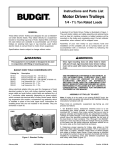
1
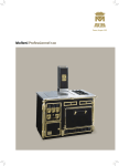
Operating instructions
Mode d'emploi
Bedienungsanleitung
Gebruiksaanwijzing
Istruzioni per l'uso
Dir. 89/336/CEE
73/23/CEE
4324344
Part 1a - INSTALLATION INSTRUCTIONS
1 - GENERAL INFORMATION
This canopy hood is designed to be fixed to any rigid vertical surface, over a cooking area.
Connect the hood to a remote blower, which may be positioned either inside or outside the home.
In certain models, the front element can be personalized by fitting wooden panels of approx 5mm
thickness.
Before commencing the installation, consideration should be given to the difficulties to be found
during installation and to the bulky weight of the hood.
The installation work must be undertaken by a qualified and competent person in conformity
to the rules concerning the evacuation of contaminated air.
The manufacturer disclaims all liability for any damage or injury caused as a result of not
following the instructions for installation contained in the following text.
2 - COMPONENTS
The cooker hood is made up of the following components (fig. 1):
No. 1 canopy C, including controls, worktop illumination and fan unit
No. 1 telescopic chimney stack formed by:
- l U-shaped upper section S
- l U-shaped lower section I
No. l extraction ducting spigot A Ø 120mm
No. l fixing kit including:
No. 4 wall brackets 1, 2, 3, 4
- rawl plugs and screws
- fixing documentation
No. l splashback B (available on request)
3 - SAFETY WARNINGS
3.1 - When used in the extraction mode the cooker hood ducting must not be connected to a flue
which is used for exhausting fumes from appliances supplied with energy other than electric
such as a central heating flue or water heating flue.
3.2 - Before connecting to the mains supply ensure that the mains voltage corresponds with the
voltage on the rating plate inside the hood.
3.3 - Connect the cooker hood to the mains via a double pole switch which has 3mm clearance
between the contacts.
3.4 - The appliance must be earthed.
3.5 - When istalled, the hood must be positioned at least 65cm above a cooking appliance.
3.6 - Never do flambé cooking under this cooker hood.
3.7 - Never leave frying pans unattended during use as overheated fats and oils may catch fire.
3.8 - Before carring out any kind of maintenance or cleaning, disconnect the hood from the mains
supply.
3.9 - If the room where the cooker hood is to be used contains a fuel burning appliance such as a
central heating boiler then this must be of the room sealed or balanced flue type.
If other types of flue or appliance are fitted ensure that there is an adequate supply of air into
the room.
When the cooker hood is used in conjunction with other appliances supplied with energy other
than electric, the negative pressure in the room must not exceed 0,04 mbar to prevent fumes
being drawn back into the room by the cooker hood.
1
ENGLISH
4 - INSTALLATION
4.1 4.2 4.3 4.4 4.5 4.6 -
For easy installation proceed as follows:
Fix the wall brackets (and the splashback, if available)
Customization of the front element
Fix the canopy
Connect the hood to the mains supply and ensure that it works properly
Connect the hood to the remote blower
Fix the telescopic metal frame
4.1 - Fix the wall brackets (and splashback)
Ref. to fig. 2:
1 - Draw a vertical line on the wall from the centre of the cooking appliance up to the ceiling, using a
marking pen. This is to ensure the correct vertical alignment of many components.
2 - Fixing the wall bracket No. 1:
a - Put the bracket 1 to the wall, aligning its marked centre across the vertical line, ensuring that the
distance between the centres of the holes and the cooking area is as follows:
1 - When the splashback is to be installed: d=L+Hmm, where H is the height of the visible part
of the splashback. As the splashback can be of different heights, the correct H figure can only
be obtained by measuring the actual height of the splashback to be fitted.
2 - Without splashback: d=L+650mm minimum.
Note: ensure that the wall bracket (1) is levelled. The hood can be aligned or adjusted in
height by rotating the adjustment screws (see below).
b - Mark on the wall the centres of the two keyholes of the bracket.
3 - Fixing the wall bracket No. 2:
a - Place bracket No. 2 on the wall aligning its centre at a distance of H+266mm from the rear edge
of the cooking appliance in the worktop.
b - Mark on the wall the centre of the two keyholes of the bracket.
4 - Fixing the wall bracket No. 3:
a - Put the bracket No. 3 to the wall at about 1-2mm from the ceiling or from the maximum height
required, paying attention to the correct vertical alignment.
b - Mark on the wall the centres of the two keyholes of the bracket.
5 - Fixing the wall bracket No. 4:
a - Put the wall bracket No. 4 to the wall, paying attention to the correct vertical alignment at a X
distance measured as in fig. 2. The X distance must equal the height of the U-shaped upper section
S, and can vary according to the different heights of this section.
b - Mark on the wall the centres of the two keyholes of the bracket.
6 - Pilot drill all the hole positions as marked on the wall using a 8mm drill. Fix the wall brackets
1 - 2 - 3 - 4 using the 8mm rawl plugs and screws supplied.
7 - Splashback (if available).
When the splashback B is to be fitted, the distance between the cooker hood and the cooking appliance
will be determined by the height of the splashback. The splashback is to be fitted before positioning
the canopy. If the splashback is to be fixed to the wall using both the upper and lower fixing points,
care must be taken to ensure that the splashback if fitted at the correct height before placing in
position the base cabinet and worktop.
Being a rather complicated operation, the fixing of the splashback should be carried out by a qualified
or competent person, knowing all the final dimensions of the furniture.
If the splashback is to be fixed through only the upper part, proceed as follows:
a - Put the splashback on the worktop as shown on fig. 2; then hold it against the wall ensuring that
it is correctly positioned on the worktop.
b - Mark on the wall the two hole positions which appear on the upper part of the splashback.
c - Pilot drill the hole positions using a 8mm drill and fix the splashback using the 8mm rawl plugs
and screws supplied.
d - The installer should ensure that the lower part of the splashback is adequately fixed.
ENGLISH
2
4.2 - Customization of the front element
1 - Remove both the active charcoal and metal filters in order to access the internal screws fixing the front
element in place.
2 - Unfasten the fixing screws and remove the front element (fig. 3).
3 - Dismantle the metal corner bracket (fig. 4).
4 - Remove the metal panel and the sheet of cardboard (fig. 5).
5 - Fit the 5 mm thick wooden panel, the metal panel and the seal element into the front element
(fig. 6). Replace the metal corner bracket. For panels over 5 mm thick, the fitter must procure a
different size of the seal element.
4.3 - Fitting the canopy (fig. 7)
1 - Rotate halfway the two screws R positioned on the hanging lugs of the canopy.
2 - Hook the canopy onto the wall bracket 1 ensuring that the two lugs of the bracket are fitted on the
keyhole fixing points of the canopy and push down as allowed by the adjustment screws R.
3 - The canopy can be aligned or adjusted in height using the two adjustment screws R.
4.4 - Electrical connection and working test
1 - The safety measures 3.2, 3.3 and 3.4 of paragraph 3 are to be strictly observed.
2 - Insert the power cable from the remote blower into the hood, remove the metal filters, remove the
plastic cover on the terminal box, connect the remote blower power cables to the terminal, ensuring
that the yellow and green wires coincide.
3 - Once the electrical connection has been completed, check that worktop illumination, motor and speeds
work properly.
4.5 - Connecting the hood to the remote blower
The hood must be connected to the remote blower using either a rigid or a flexible duct Ø 150 mm
(fig. 8).
In this case it will be necessary to fit a Ø 150-120mm adapter to the hood outlet.
If the remote blower is installed inside the home, it must be ducted to the outside:
a - Remove the two screws on top of the canopy and secure the spigot (fig. 9); fit the spigot A on
the rectangular air outlet on the top of the canopy and secure the spigot to the canopy using the
two screws.
b - Connect the reduction flange to both the ducting spigot A and to the remote blower using a
Ø 150mm duct.
c - Connect the remote blower to the evacuation duct. The choice of the material to be used is left
to the installer.
4.6 - Fitting the telescopic chimney stack (fig. 10)
The chimney stack is formed using the two U-shaped sections and is adjustable for different heights.
1 - To fit the upper section S first widen the two sides of the section slightly so that they can be clamped
to the wall brackets 3 and 4 and then ensure that they are correctly fastened. The upper section is fixed
to the wall bracket 3 with its upper corners. Secure the upper section to the bracket 3 using two screws
provided with the fixing kit.
2 - The lower section I of the chimney stack can be fixed in a similar way between the wall brackets 2
and 4 and the wall, paying attention to fit the lower part of the section into the recess of the canopy
(see close-up).
Then fix the lower section I to the wall bracket 2 using the two remaining self tapping screws.
NOTE - The upper S and lower I sections are fixed to the wall bracket in the middle 4 through a
spring and the connection is made by pushing both sections vigorously towards the centre.
3
ENGLISH
Part 2a - OPERATION AND MAINTENANCE INSTRUCTIONS
1 - SAFETY WARNINGS
1.1 1.2 -
1.3 1.4 -
It is most important that all the warnings shown in paragr. 3 of the Installation instructions are
strictly observed.
Moreover pay special attention to the following warnings during the use and maintenance of the
cooker hood:
The grease filters should be cleaned or replaced as recommended by the manufacturer or more
frequently if the hood is used consistently (over 4 hours per day).
When using a gas hob in conjunction with the cooker hood, never leave the burners uncovered
while the hood is in use; when removing the pans either turn the hob off or keep the flame to
a minimum if it is only for a few minutes and under supervision.
Always ensure that the flame does not overflow from under the pans; this will save energy and
will avoid a dangerous concentration of heat.
Do not use the appliance in any incorrect way: this hood has been designed only to reduce the
smells of cooking in the kitchen.
2 - OPERATION
2.1 - Control panel
The cooker hood functions are located in a concealed control panel on the right hand side of the
canopy, behind the front trim (fig. 11).
To gain access to the control panel apply slight pressure to the control panel back and release.
To relocate the control panel in its concealed position just push it back upwards.
2.2 - Switches
The cooker hood can be operated as follows (fig. 12):
Switch L = marked with the lamp symbol, controls the worktop illumination;
Switch M = marked with the fan symbol, controls the power to the fan motor (0-1);
Switch V = controls the fan speed:
• low speed should be selected when simmering or using only one pan; the noise level is kept to the
minimum;
• medium speed, should be selected for normal cooking. This speed offers the best ratio between air
capacity and noise level;
• top speed, should be selected when frying or cooking food with strong odours, even for a long
period.
3 - MAINTENANCE
Regular maintenance and cleaning will ensure good performance and reliability, while extending the
working life of the hood.
Special attention should be paid to the grease filters.
3.1 - Metal grease filters
a - Cleaning:
The metal grease filters should be cleaned every two months with normal usage and can be cleaned
in a dishwasher or by hand using mild detergent or liquid soap.
b - Replacement:
The metal grease filter panels are easily removed, one at a time, by applying slight inward pressure
to the actuators to release the securing bolts. Care should be taken to support the filter with one hand
while releasing the securing bolts with the other hand (fig. 13).
The filter panels should be refitted with bolt side facing downwards.
ENGLISH
4
3.2 - Thin synthetic filter
On certain models the metal grease filters are replaced with a lower grille panel containing a paper
filter with saturation indicators.
a - Cleaning:
The paper filter visible through the perforated metal grease filter tray cannot be washed and
should be replaced when the violet dots are spead over the whole surface of the filter.
b - Replacement:
To remove the filter for subsequent replacement first open the metal grille panel (fig. 14,a) to the stop
position.
To remove the metal grille panel slide the right hand side of the panel forward until the hinge pin
comes away from the recess in the side casing (fig. 14,b).
The filter is easily removed from the grille by pushing the wire clips (item Q) to one side and
removing (fig. 14,c).
Replace the filter making sure that the saturation indicators face downwards.
Replace by reversing the operation ensuring that the lower grille is securely fastened to the side
casing.
ATTENTION - THERE COULD BE A POSSIBLE FIRE HAZARD IF THE FILTERS ARE
NOT REPLACED ACCORDING TO THESE INSTRUCTIONS.
3.3 - Worktop illumination
A 15W fluorescent strip lamp or two 40W lamps ensure the illumination of the worktop.
To replace the strip lamp or the lamps operate as follows as illustrated in fig. 15:
- Remove the lighting diffuser by unscrewing the screw in the metal clip (item T) near the control
box.
- The glass diffuser is kept in position by the retaining lugs (item Z). Pull the glass diffuser slightly
down as shown by arrow 2, then slide the glass backwards as directed by arrow 3, until the glass
diffuser can be removed.
- When changing the lamps or the fluorescent strip lamp, an identical replacement must be fitted to
ensure the safe working of the cooker hood.
- To refit the glass diffuser, reverse the operation.
3.4 - Cleaning
When cleaning the hood:
- Never use a wet cloth or sponge, or running water.
- Never use thinners or products containing alcohol, as they might damage the paintwork.
- Never use abrasive cleaning materials, in particular when cleaning stainless steel surfaces.
It is recommended to use a damp cloth and mild liquid household cleaner.
1ère Partie - INSTRUCTIONS POUR L’INSTALLATION
1 - GENERALITES
Cette hotte est destinée à être installée au mur, au dessus d’un plan de cuisson. Elle doit être branchée
à un seul aspirateur qui peut être installé soit à l’extérieur soit à l’intérieur d’un logement.
Dans certains modèles, le panneau frontal peut être personnalisé grâce à des panneaux en bois ayant
une épaisseur d’environ 5 mm.
A cause de la complexité et du poids de l’appareil il est préférable que l’installation soit effectuée
par un spécialiste tout en respectant les prescriptions des autorités concernant l'évacuation de
l'air.
La responsabilité du producteur ne saurait être engagée pour tout incident ou accident provoqué
par une installation défectueuse.
2 - COMPOSANTS
La hotte se compose de (fig. 1):
n. 1 corps de hotte C complet avec commandes, éclairage et groupe d’aspiration
n. 1 cheminée téléscopique composée de:
- 1 demi-cheminée supérieure S
- 1 demi-cheminée inférieure I
n. 1 raccord aspirant A Ø 120
n. 1 sachet contenant 4 brides, 1, 2, 3, 4
- 1 sachet accessoires avec vis, chevilles et colliers
n. 1 panneau mural B (en option)
3 - CONSEILS CONCERNANT LA SECURITE
3.1 - N’utilisez jamais pour le raccordement une cheminée servant de conduit de fumée (chaudières,
cheminées, etc...).
3.2 - Vérifiez que la tension du secteur soit identique aux valeurs indiquées sur la plaquette signalétique
figurant à l’intérieur de la hotte.
3.3 - Reliez la hotte au réseau en interposant un interrupteur bipolaire avec ouverture des contacts
de 3 mm au moins.
3.4 - Assurez-vous que l’installation éléctrique de votre logement ait une mise à la terre correcte.
3.5 - La distance de sûreté minimum entre le plan de cuisson et la hotte est de 65 cm.
3.6 - Il est interdit de faire flamber des préparations sous la hotte.
3.7 - Lorsque des fritures sont effectuées sous la hotte en fonctionnement, elles doivent faire l’objet
d’une surveillance permanente: l’huile surchauffée pourrait s’enflammer.
3.8 - Avant d’effectuer le nettoyage ou l’entretien de la hotte, débranchez l’appareil ou agissez sur
l’interrupteur omnipolaire de votre installation.
3.9 - Une ventilation convenable de la pièce doit être prévue si une hotte de cuisine et des appareils
alimentés par une énergie autre que l’énergie électrique évacuent les fumées simultanément.
Une utilisation sans dangers est possible si la dépression maximum qui se crée dans la pièce est
inférieure à 0,04 mbar, ce que évite un retour des gaz de décharge dans la pièce.
4 - INSTALLATION
Pour une installation plus facile, respectez l’ordre des opérations suivantes:
4.1 - Montage des brides de support. Panneau mural (en option)
4.2 - Personnalisation du panneau frontal
4.3 - Montage du corps de hotte
5
ENGLISH
FRANÇAIS
6
4.4 - Raccordement électrique et contrôle fonctionnel
4.5 - Connexion à l'installation d'aspiration
4.6 - Montage de la cheminée téléscopique
4.1 - Montage des brides de support
Panneau mural (fig. 2):
1 - Tracez sur le mur une ligne verticale, jusqu’au plafond, au centre de l’endroit prévu pour le montage
de la hotte: elle sert pour effectuer l’alignement vertical des différentes parties.
2 - Positionnement de la bride 1:
a - Placez la bride 1 sur le mur, en alignant son centre sur la ligne verticale, à une distance entre l’axe
de ses trous et le plan de cuisson de:
1 - Avec panneau mural: d= L+H mm, où H= hauteur en mm de la partie visible du panneau.
Cette cote, à cause des différents types de panneaux disponibles, doit être mesurée directement
sur le panneau en dotation.
2 - Sans panneau: d= L+650 mm au moins.
Nota: Vérifiez que la bride 1 est en position horizontale. Vous pouvez l’ajuster en agissant
sur les vis de réglage de la hotte (voir plus bas).
b - Marquez sur le mur les centres des deux boutonnières de la bride.
3 - Positionnement de la bride 2:
a - Placez la bride 2 sur le mur en alignant son centre, à une distance H+266mm du bord postérieur
du plan de cuisson.
b - Marquez sur le mur le centre des deux boutonnières de la bride.
4 - Positionnement de la bride 3:
a - Placez la bride 3 sur le mur à environ 1-2 mm du plafond ou de la limite supérieure en l’alignant
verticalement.
b - Marquez sur le mur le centre des deux boutonnières de la bride.
5 - Positionnement de la bride 4:
a - Placez la bride 4 sur le mur, en l’alignant verticalement, à une distance X mesurée comme à la
fig. 2, identique à la hauteur de la demi-cheminée supérieure S fournie avec la hotte.
La cote X peut avoir différentes valeurs, selon la hauteur de la demi-cheminée supérieure.
b - Marquez sur le mur les centres des boutonnières de la bride.
6 - Percez les centres marqués avec un foret Ø 8 mm. Fixez les brides 1, 2, 3, 4 à fond, en utilisant les
chevilles Ø 8 mm et les vis fournies avec l’appareil.
7 - Panneau mural (en option).
La hauteur de la hotte du plan de cuisson est déterminée dans ce cas par la hauteur du panneau B et
par l’éventuelle hauteur du bord arrière du plan de la base.
Le panneau doit être monté avant de monter le corps de hotte, et si on veut le fixer au mur soit en
haut qu’en bas, il est nécessaire de le monter à la juste hauteur, avant de monter la base ou du moins
le plan supérieur.
A cause de la complexité de l’opération, il est préférable que l’installation soit effectuée par un
spécialiste ou par une personne qui connaisse les dimensions finales des meubles.
En se limitant seulement à la fixation en haut respectez l’ordre des opérations suivantes:
a - Mettez le panneau sur le plan de la base comme à la fig. 2, placez-le contre le mur et centrez-le
par rapport à la base.
b - Marquez sur la paroi les deux trous supérieurs.
c - Percez deux trous de Ø 8 mm et fixez le panneau en utilisant les chevilles Ø 8 mm et les vis en
dotation.
d - L’éventuelle stabilisation de la partie inférieure, si nécessaire, est laissée à l’installateur.
3 - Démonter la cornière métallique (fig. 4).
4 - Enlever le panneau métallique et le carton (fig. 5).
5 - Introduire, dans le panneau frontal, le panneau en bois ayant 5 mm. d’épaisseur, le panneau métallique
et la garniture (fig. 6). Remonter la cornière métallique. Pour des panneaux ayant une épaisseur de
plus de 5 mm., l’installateur doit se procurer une garniture ayant des dimensions différentes.
4.3 - Montage du corps de hotte (fig. 7)
1 - Réglez les deux vis R situées sur les points d’accrochage de la hotte environ en position médiane.
2 - Accrochez le corps de hotte à la bride 1 en insérant les deux languettes dans les parties larges des
boutonnières pour l’accrochage et poussez vers le bas jusqu’au fond de la course déterminée par les
vis de réglage R.
3 - Réglez verticalement et nivelez horizontalement la hotte en utilisant les 2 vis R.
4.4 - Raccordement électrique et contrôle fonctionnel
1 - Il est nécessaire de respecter scrupuleusement les conseils 3.2, 3.3, 3.4 du paragraphe 3 concernant
la sécurité.
2 - Introduire le câble électrique de l’aspirateur externe dans la hotte, enlever les filtres métalliques,
enlever le couvercle en plastique du boîtier du circuit électrique, brancher les fils du câble électrique
de l’aspirateur externe dans la boîte à bornes en faisant coïncider les couleurs jaune-vert.
3 - Le raccordement électrique effectué, vérifiez le bon fonctionnement de l’éclairage, du moteur et du
changement des vitesses d’aspiration.
4.5 - Branchement à l’installation d’aspiration
La hotte doit être branchée à l’aspirateur à l’aide d’un tuyau rigide ou flexible Ø 150 mm (fig. 8).
Dans ce cas, il faut repérer une réduction Ø 150-120 mm à appliquer sur la sortie de la hotte.
Si l’aspirateur est installé à l’intérieur du logement, il doit être relié à des tuyaux extérieurs:
a - Retirez les deux vis positionnées sur les deux côtés de la sortie de l'air (fig. 9) et appliquez le
raccord A sur la partie supérieure de la hotte de façon à recouvrir la sortie rectangulaire du
diffuseur. Fixez avec les deux vis.
b - Fixez la réduction au raccord A et à l'aspirateur en utilisant un tuyau Ø 150 mm.
c - Reliez l'aspirateur au conduit d'évacuation extérieur.
Le matériel nécessaire pour cette dernière opération doit être repéré par l’installateur.
4.6 - Montage de la cheminée téléscopique (fig. 10)
1 - Pour appliquer la demi-cheminée supérieure S, élargissez légèrement les deux pans latéraux, accrochezles derrière les brides 3 et 4 et refermez-les jusqu’à la butée. La demi-cheminée reste accrochée sur
les plis supérieurs, à la bride 3. Fixez-la à la bride 3 avec les deux grandes vis fournies avec l’appareil.
2 - Appliquez de la même façon la demi-cheminée inférieure I entre les brides 2 et 4 et le mur, en tenant
compte qu’à la base, il est nécessaire d’insérer le périmètre de la demi-cheminée dans le logement
spécial du corps de la hotte (voir agrandissement). Fixez la demi-cheminée I à la bride 2 avec les deux
vis fournies avec l’appareil.
N.B. - L’accrochage des demi-cheminées S et I en correspondance de la bride centrale 4, s’effectue
par un système de ressort; pour cela, poussez énergiquement vers le centre.
4.2 - Personnalisation du panneau frontal
1 - Enlever les filtres aussi bien métalliques qu’au charbon actif pour accéder aux vis internes fixant le
panneau frontal.
2 - Dévisser les vis de fixation et enlever le panneau frontal (fig. 3).
7
FRANÇAIS
FRANÇAIS
8
3.2 - Filtri in fibra sintetica
a - Sostituire quando il colore rosso-violaceo dei punti, visibili attraverso la griglia, si è diffuso su gran
parte della superficie totale del filtro e, in ogni caso, non oltre 2 mesi di uso.
N.B. - Questo filtro non può essere lavato, perchè perderebbe tutte le sue caratteristiche.
Il fabbricante declina ogni responsabilità per danni derivanti dall'inosservanza di questa norma.
b - Modalità per la sostituzione:
- Aprire la griglia (fig. 14,a) premendo i tasti U verso la parte posteriore fino a fondo corsa.
- Ruotare la griglia verso il basso, sganciarla dai perni posteriori con un movimento diagonale
(fig. 14,b).
- Appoggiare la griglia su un piano e togliere i fermafiltri Q come indicato in (fig. 14,c).
- Sostituire il filtro in modo che i punti colorati siano rivolti verso la griglia.
- Rimontare i fermafiltri e la griglia con il procedimento inverso, avendo cura di verificare che i ganci
metallici comandati dai tasti U siano entrati fino in fondo nella loro sede.
ATTENZIONE: è necessario rispettare i tempi di manutenzione o sostituzione indicati, per
evitare un possibile rischio di incendio in caso di filtri saturi di grassi.
3.3 - Illuminazione
È costituita da 1 tubo al neon da 15W, o da 2 lampade da 40W.
Per effettuare una sostituzione operare come segue (fig. 15):
- Togliere il terminale metallico T adiacente la scatola comandi. Il vetro rimane agganciato sulle
linguette Z.
- Far scorrere il vetro verso la scatola comandi fino a liberare la punta opposta (freccia 1), quindi
tirare leggermente verso il basso (freccia 2) e poi far scorrere in senso inverso a quello iniziale
(freccia 3) fino a liberare totalmente il vetro.
- Sostituire le lampade o il neon e rimontare il vetro con sequenza inversa.
1
3.4 - Pulizia
Per la normale pulizia della cappa:
- Non utilizzare panni o spugne bagnate, nè getti d'acqua.
- Non utilizzare diluenti o alcoli poiché potrebbero opacizzare le superfici verniciate.
- Non utilizzare sostanze abrasive, in particolare sulle superfici in acciaio inox.
Si consiglia di utilizzare un panno umido e detersivo liquido neutro.
2
25
ITALIANO
26
3
4
8
5
7
27
9
6
10
28
11
12
13
15
29
14
30