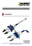
1
Operating instructions
Rescue equipment
Mobile Selection Manifold
MSM-2D PN500 - STREAM
1
3
5
179003085 GB
Issue 03.2009
2
4
6
6
(Translation of the original operating instructions)
Contents
Page
1. Danger classes
3
2. Product safety
4
3. Safety rules for hydraulic hose lines
7
4. Proper use
7
5. Functions and performance capabilities
7
5.1 Description
7
5.2 Circuit diagram
8
5.3 Hydraulic supply
9
5.4 Control of the work movements
9
5.5 Connection between Mobile Selection Manifold and motor pump
9
5.6 Connection between control module and hydraulic cylinders
9
6. Connection of the devices
9
6.1 Hydraulic
9
6.2 Connecting the monocouplings
10
6.3 Connecting the quick-disconnect couplings
11
7. Operation
11
7.1 Preparatory measures
11
7.2 Operation of the Mobile Selection Manifold
12
7.3 Removal of the components
13
8. Care and maintenance
14
9. Repairs
15
9.1 General
15
9.2 Preventative service
15
9.3 Repairs
16
10. Troubleshooting
19
11. Technical data
20
21
11.1 Hydraulic fluid recommendations
11.2 Hose lines
21
11.3 Operating temperature range
21
12. EC Conformity declarations
22
13. Notes
23
2
1. Danger classes
We distinguish between various categories of safety instructions. The table shown below
shows you the overview, via the assignment of symbols (pictograms) and signal words, of
the concrete danger and the possible consequences.
Damage /
injury to
Key word
Definition
Consequences
DANGER!
Immediate danger
Death or major
injury
WARNING!
Potentially
dangerous
situation
Potential death or
major injury
CAUTION!
Less dangerous
situation
Minor or slight
injury
CAUTION!
Danger of damage
to device /
environment
Damage to the
equipment,
damage to the
environment,
damage to
surrounding
materials
NOTE
Advice for
application and
other important /
useful information
and advice
No injury /
damage to
persons /
environment /
equipment
device
human
Pictogram
-
Wear helmet with face guard
Wear protective gloves
Wear safety shoes
Proper recycling
Protect the environment
Read and follow operating instructions
3
2. Product safety
LUKAS products are developed and produced in order to ensure the best performance and
quality with proper use.
The safety of the operator is the most important consideration in the product design.
In addition, the operating instructions are meant to help in using the LUKAS products safely.
In addition to the operating instructions, all generally applicable, statutory and other
binding rules for accident prevention and for environmental protection must be heeded and
disseminated.
The device must only be operated by educated persons who are trained in safety technology,
since otherwise there is a risk of injury.
We advise all users before using the device to carefully read through the operating instructions
and to follow the instructions contained therein without exception.
We also recommend that you get instructed by a qualified trainer in the use of the product.
WARNING / CAUTION!
The operating instructions for the hoses, the accessories and the connected
devices must also be heeded!
Even if you have already received instruction, you should read the following safety instructions
again.
WARNING / CAUTION!
Make sure that the accessories used and the connected devices are suitable
for the specified max. operating pressure!
Refrain from any work
procedure that detracts from
the safety and/or stability of the
device!
Wear protective clothing,
protective helmet with visor,
safety shoes and protective
gloves.
Immediately report changes
that occur (including changes
in operating behaviour) to
the appropriate persons/
departments! If necessary,
immediately shut down and
secure the device!
Check the device for visible
defects or damage before and
after use.
Check all lines, hoses and
screwed connections for leaks
and externally visible damages
and repair immediately!
Escaping hydraulic fluid can
lead to injuries and fires.
Working under loads is
prohibited if they are raised
exclusively with hydraulic
devices. If this work is
unavoidable, sufficient
mechanical supports are
additionally required.
4
In the event of malfunctions,
shut down the device
immediately and secure it. You
should have the malfunction
repaired immediately.
Do not make any changes
(add-ons or conversions) on the
device without the approval of
LUKAS.
Heed all safety instructions
and hazard warnings on the
device and in the operating
instructions.
All safety instructions and
hazard warnings on the device
are to be kept intact and in a
legible condition.
Make sure that all safety covers
are present on the device and
in proper working condition.
Safety equipment must never
be disabled!
Before switching on/engaging
the device or while operating
the device, it must be ensured
that no one is endangered by
the operation of the device.
The maximum permissible
operating pressure must not be
changed.
Prevent electrostatic discharge,
which has the possible
consequence of spark
formation, when handling the
device.
Observe all intervals that
are prescribed or specified
in the operating instructions
for recurring tests and/or
inspections.
When working in the vicinity
of live components and lines,
take appropriate measures for
preventing current transfers or
high voltage flashovers to the
device.
Use only original LUKAS
accessories and spare parts for
repairs.
The device is filled with
hydraulic fluid. These hydraulic
fluids can be detrimental to
health if they are swallowed
or their vapours are inhaled.
Direct contact with the skin
should be avoided for the same
reason. Also, when handling
hydraulic fluids, note that they
can negatively affect biological
systems.
When operating and/or storing
the device, make sure that the
function and the safety of the
device are not impaired by
strong external temperature
differences or that the device is
damaged. Keep in mind that the
device can also heat up when it
is used continuously.
Make sure that you do not get
caught in the hose or cable
loops and trip when working
with or transport the device.
5
Make sure there is adequate
lighting while working.
Before transporting the device,
always check to see that the
accessories are positioned
securely to prevent the
possibility of an accident.
Always keep these operating
instructions easily accessible
at the site where the device is
used.
Make sure you properly dispose
of all removed parts, leftover
hydraulic fluid, leftover oil and
packing materials.
In addition to the safety instructions of these operating instructions, all generally applicable,
statutory and otherwise binding national and international rules for accident prevention need
to be heeded and disseminated!
WAR N IN G / C A U TION / AT T E NT I O N!
The device is specified exclusively for the purpose represented in the operating
instructions (see Chapter "Proper use"). Any use that differs or goes beyond this is
considered improper. The manufacturer/supplier shall not be held liable for damages
resulting from improper use. The risk shall be borne solely by the user.
Proper use also includes heeding the operating instructions and complying with the inspection
and maintenance requirements.
Never work in a fatigued or intoxicated state!
6
3. Safety rules for hydraulic hose lines
For more information, consult the separate operating instructions for the hose lines
(116500085).
4. Proper use
The Mobile Selection Manifold is designed specifically to control the piston movement of
LUKAS hydraulic cylinders (without independent control valve).
The Mobile Selection Manifold makes it possible to sensitively control the extension and
retraction movement of the hydraulic cylinders in order to raise an object at two contact
points with the pistons having the same travel speed (even when the load distribution of the
object to be raised varies).
It is used, for example, in the event of traffic accidents, train crashes, building collapses, etc.
In principle, nearly all hydraulic cylinders without an independent control valve can be driven
or their piston travel speed controlled without an independent control valve.
WARNING / CAUTION!
All objects that are to be moved need to be secured via fixed brackets or by using
substructures. In addition, it needs to be ensured that the hydraulic cylinders used
cannot slip away.
WARNING / CAUTION / ATTENTION!
The hydraulic cylinders may not be placed against:
- live cables
- explosive elements such as air bag cartridges
NEVER operate the Mobile Selection Manifold with a higher inlet operating
pressure than in the "technical data" chapter. A higher setting may cause property
damage and/or injuries.
Accessories and spare parts for the device can be obtained from your authorised LUKAS
dealer!
5. Functions and performance capabilities
5.1 Description
The Mobile Selection Manifold controls the travel speed of the connected hydraulic cylinder
via the distribution of the supplied hydraulic fluid.
The Mobile Selection Manifold consists of:
- a control valve (cover sheet, item 1) for defining the direction of movement of the lifting
cylinders (double-acting or single-acting cylinder components) via star knob,
- distribution valve (cover sheet, item 2) with hand wheel for the hydraulic fluid distribution
to the connected cylinder,
- pressure relief valves for the extension and retraction (firmly lodged within the device
body) to protect the hydraulic system,
- supply hose (cover sheet, item 4) and return hose (cover sheet, item 3) for the hydraulic
fluid supply.
These two hoses are connected via a monocoupling (cover sheet, item 5) or a quickdisconnect coupling pair to the hydraulic unit,
- Ports A1 and B1 or A2 and B2 are connected to the hydraulic cylinders via a quickdisconnect coupling pair (cover sheet, item 6).
7
5.2 Circuit diagram
Cylinder 2
Cylinder 1
Charge
retaining
valve
B1
A1
B2
A2
Charge
retaining
valve
Distribution
valve
Pressure
relief
valve
Pressure
relief
valve
50 MPa
30 MPa
Control
valve
30+5 MPa
open air spraying
8
5.3 Hydraulic supply
The hydraulic supply must be provided via a LUKAS hydraulic unit.
NOTE:
You should always contact LUKAS or an authorised dealer before using pumps
of other producers.
5.4 Control of the work movements
The direction of the piston movement is determined via the control valve (cover sheet, item 1).
This is controlled via the distribution valve (cover sheet, item 2).
5.5 Connection between Mobile Selection Manifold and motor
The Mobile Selection Manifold and pump unit are connected via hose lines.
There are already two short hose lines with a monocoupling connection or a quick-disconnect
coupling pair on the Mobile Selection Manifold. If the length of hose lines is not sufficient for
connecting to the pump units, then the connection can be extended by using LUKAS hose
pump
The Mobile Selection Manifold and hydraulic cylinders are connected via hose lines.
They are not included within the scope of delivery of the Mobile Selection Manifold!
The hose lines are connected exclusively via quick-disconnect couplings.
6.1 Hydraulic
6. Connection of the devices
Two short hose lines with a monocoupling or a quick-disconnect coupling pair are provided
on the device side; they are connected to the pump unit via a hose pair.
Two quick-disconnect male couplings and two quick-disconnect female couplings are
provided for the connection to the hydraulic cylinders. They are connected to hydraulic
cylinders via hoses / hose pairs. Each is equipped, respectively, with quick-disconnect male
coupling A1 and quick-disconnect female coupling B1 and quick-disconnect male coupling
A2 and quick-disconnect female coupling B2.
All hose lines are colour-coded in order to ensure a distinction between supply and return line.
In connection with the couplings installed on the added hose lines and on the hose line
extensions (accessories), a non-reversible connection to the device is ensured.
NOTE:
When controlling single-acting cylinders, the connection to ports B1 and B2 is
omitted.
9
WARNING / CAUTION / ATTENTION!
Make sure that the connected devices and the connected
accessories are suitable for the max. operating pressure!
Please consult the "Technical data" chapter to find the maximum
operating pressure between hydraulic unit and Mobile Selection
Manifold and the maximum operating pressure between Mobile
Selection Manifold and hydraulic cylinder.
6.2 Connecting the monocouplings
The device is connected via mono coupling halves (female and male) to the hydraulic pump
in such a way that they cannot be reversed.
Dust caps
Male
coupling
Female
coupling
Before coupling, remove dust caps, then connect male and female couplings and turn locking
sleeve of the female coupling in direction "1" until the locking sleeve latches. The connection
is then made and secured. Decouple by turning the locking sleeve in direction "0".
The coupling of the devices under pressure is also possible, assuming the connected
equipment is not turned on.
The supplied dust caps must be reattached to protect against infiltration of dust.
NOTE:
We recommend, when ambient temperatures are low and extension hoses /
hose winders are used, connecting the coupling halves in a depressurised state
because decoupling may otherwise require a very large exertion of force.
WARNING / CAUTION / ATTENTION!
The monocouplings must not be unscrewed and/or the hose lines reversed!
10
6.3 Connecting the quick-disconnect couplings
The hydraulic cylinders and the hydraulic unit are connected to the Mobile Selection Manifold
via quick-disconnect halves (female and male) in such a way that they cannot be mistakenly
reversed.
X
Y
Before connecting the couplings, remove the dust cap, then pull back and hold the locking
sleeve of the female coupling (Position X). Push the male and female couplings together and
release the locking sleeve. Finally, turn the locking sleeve into Position Y. The connection is
then made and secured. Decoupling is done in the reverse sequence.
NOTE:
Making the coupling connection is only possible if the hoses are depressurised.
The supplied dust caps must be reattached to protect against infiltration of dust.
WARNING / CAUTION / ATTENTION!
The quick-disconnect couplings have special functions, in part, and therefore
must not be unscrewed and/or reversed!
NOTE:
When controlling single-acting cylinders, omit the connection to the quickdisconnect female couplings.
7. Operation
7.1 Preparatory measures
WARNING / CAUTION!
Before the system components are installed, the vehicle to be raised / the load to
be raised needs to be properly secured against rolling and slipping away according
to the respective applicable national / international guidelines and regulations!
11
7.1.1 Installing system components
Procedure:
1. First, set up the hydraulic unit in a suitable location, i.e. on a flat surface at a safe distance
from the load to be lifted.
2. Then, set up the hydraulic cylinders that are to raise the load.
ATTENTION!
During the installation, make sure that:
- the base is anti-slip and level (if necessary, use a suitable base pad).
- the cylinders are never used without piston guard plates.
- the cylinders are stable (if necessary, use base plates or similar items).
- a pressure-tight, anti-slip base pad is always used between piston guard
plate and load lifting point.
3. Install the Mobile Selection Manifold at a safe distance from the load to be raised.
4. Connect the hydraulic cylinder to the Mobile Selection Manifold as described in the
"Connecting the equipment" chapter.
NOTE:
When using double-acting hydraulic cylinders, always first connect lines B1,
B2 and return line to the pump!
5. Connect the hydraulic unit to the Mobile Selection Manifold as described in the "Connecting
the equipment" chapter.
7.1.2 Preparing for operation
Procedure:
1. Check the fluid levels of the hydraulic unit
2. Make the hydraulic unit operationally ready. (see separate operating instructions of the
hydraulic unit)
3. Start the hydraulic unit
7.2 Operation of the Mobile Selection Manifold
7.2.1 Control valve (cover sheet, item 1)
The movement of the lift cylinder is determined with the control valve.
Extend piston (
):
Turn star grip in the clockwise direction (in the direction of the
corresponding symbol) and hold it in this position.
Retract piston (
):
Turn star grip in the anti-clockwise direction (in the direction of the
corresponding symbol) and hold it in this position.
“Dead man” circuit:
After it is released, the star grip automatically returns to the central
position with complete assurance of holding the charge.
12
7.2.2 Distribution valve (cover sheet, item 2)
The movement is controlled with the distribution valve. Turning the hand wheel controls
which port is supplied with more hydraulic fluid. The fluid supply of the other port can be
throttled down to almost 0.
The extension and retraction speed of the hydraulic cylinders is indirectly affected by
controlling the fluid quantity.
increased supply of the
cylinder at the connection
A2 - B2
Central position, i.e. both
cylinders are supplied
evenly with hydraulic fluid.
increased supply of the
cylinder at the connection
A1 - B1
7.2.3 Pressure relief valve
The pressure relief valves are adjusted to a set pressure and secured.
WARNING / CAUTION / ATTENTION!
The pressures set on the pressure relief valves may not be changed without the
direct permission of LUKAS!
NOTE:
The system pressure that is generated between the Mobile Selection Manifold
and hydraulic cylinders is not identical to the system pressure between the
Mobile Selection Manifold and hydraulic unit! (Consult the "Technical Data" data
7.3 Removal of the components
The components are removed in reverse order from the installation.
ATTENTION!
Before the final removal of the system components, it is absolutely essential to
ensure:
- that the load is located in a stable, immovable position.
- all hydraulic cylinders are retracted to approx. 10 mm (0.39 in.).
- the hydraulic unit is stopped.
- the hose lines to the hydraulic cylinders are depressurised.
13
8. Care and maintenance
A visual inspection needs to be performed after each use, but at least once every year. Every
3 years, or if there is a doubt about the safety or reliability, a functional check should be also
performed (In so doing, also heed the corresponding applicable national and international
specifications related to the maintenance intervals of rescue devices). In the Federal
Republic of Germany, regular safety technology tests are prescribed in accordance with the
regulations of Statutory Accident Insurance (GUV).
ATTENTION!
Clean off any dirt before controlling the equipment!
WARNING / CAUTION / ATTENTION!
To perform maintenance and repairs, personal safety equipment appropriate
for the work is an absolute requirement.
Tests to be performed:
Visual inspection
Mobile Selection Manifold
• Mobile Selection Manifold without damage and deformation,
• General leak-proofness (leakages),
• The freedom of movement of the control valve and the distribution valve,
• All screw connections tightened,
• Identification plate and direction symbols legible,
• Couplings easy to connect,
• Dust caps in place.
• All protective covers in place and undamaged.
Hoses
• Visual inspection for obvious damage,
• Check for leaks.
Functional check (only when operation of the complete system is possible)
• Cylinder easy to retract,
• No additional movement of the cylinder when the control valve is released during the
process (dead man circuit),
• Control of the travel speed can be affected evenly and continuously,
• No suspicious noises.
NOTE:
Before the functional check of the Mobile Selection Manifold, check the additional
system components (cylinder, hydraulic unit, etc.) for correct operation.
14
9.1 General
9. Repairs
Service work may only be performed by the device manufacturer or by personnel trained by
the device manufacturer and authorised LUKAS dealers.
For all components, only original LUKAS replacement parts may be supplied in exchange,
as are listed in the spare parts list, because in this way also any required special tools,
assembly instructions, safety aspects, tests absolutely must be taken into consideration
(see also the chapter "Care and maintenance" for more information).
During the assembly work, pay particular attention to the cleanliness of all components
because dirt can damage the rescue equipment!
WARNING / CAUTION / ATTENTION!
Wear protective clothing when making repairs because the devices may be
under pressure even in the idle state.
NOTE:
Always mail the warranty registration card back to LUKAS Hydraulik GmbH.
Only in this way will you have a claim to the extended warranty coverage.
NOTE:
You should always contact LUKAS or an authorised dealer before using externally
supplied couplings.
ATTENTION!
Because LUKAS rescue equipment is designed for the highest performance,
only components may be replaced that are listed in the spare parts lists of the
corresponding device.
Additional components of the equipment may only be replaced if:
- You have participated in a corresponding LUKAS service training course.
- You have the express permission of LUKAS Customer Service (by request,
check on the grant of permission. A check is necessary in each individual
case).
9.2 Preventative service
9.2.1Care instructions
The exterior of the device needs to be cleaned from time to time and the metallic surfaces
need to be rubbed with oil to protect against corrosion.
9.2.2Functional check
If there are doubts about safety or reliability, a functional check also needs to be performed.
15
9.3 Repairs
9.3.1Replace or tighten hoses
Hose connection of the pressure and/or return line leaky or hoses defective. Tighten the
hose connections on the Mobile Selection Manifold.
(Attention! Observe tightening torque MA = 40 Nm!)
NOTE when monocouplings are used:
In order to change the hoses, the connected monocouplings must first be removed.
ATTENTION (with monocoupling system)!
Make sure that the "T" joint of the Mobile Selection Manifold is always connected
to the "T" joint of the monocoupling!
ATTENTION (with quick-disconnect coupling system)!
The return hose on the hose line extensions (accessories) must always be
equipped with a quick-disconnect male coupling.
The supply hose line should instead be equipped with a quick-disconnect female
coupling.
9.3.2 Monocouplings
The monocouplings must be replaced if:
- exterior damage is present,
- the lock does not function,
- in the coupled and/or decoupled state, hydraulic fluid continuously escapes.
WARNING / CAUTION / ATTENTION!
Couplings must not be repaired; they must be replaced with original LUKAS
parts!
During installation, tighten the coupling nuts of the hose line with a torque of MA = 40 Nm.
Procedure:
1. Pull back cover from the couplings.
16
2. Loosen coupling nuts of the hose lines and remove coupling.
3. Set new coupling in place and tighten coupling nuts of the hose lines with a torque of MA = 40 Nm and slide the cover of the couplings back on.
ATTENTION!
Make sure that the "T" joint of the Mobile Selection Manifold is always connected
to the "T" joint of the monocoupling!
9.3.3 Quick-disconnect couplings
The quick-disconnect couplings should be replaced if:
- exterior damage is present,
- the lock does not function,
- in the coupled and/or decoupled state, hydraulic fluid continuously escapes.
WARNING / CAUTION / ATTENTION!
Couplings must not be repaired; they must be replaced with original LUKAS
parts!
During installation in the valve block, tighten the coupling with a torque of MA = 40 Nm.
Procedure:
1. Unscrew coupling from the Mobile Selection Manifold.
2. Fit new coupling and screw on with a torque of MA = 40 Nm.
ATTENTION!
The couplings need to be installed as illustrated on the cover sheet!
17
ATTENTION!
The return hose on the hose line extensions (accessories) must always be
equipped with a quick-disconnect male coupling.
The supply hose line should instead be equipped with a quick-disconnect female
coupling.
9.3.4 Decals
All damaged and/or illegible decals (safety instructions, name plates, etc.) must be replaced.
Procedure:
1. Remove damaged and/or illegible decals.
2. Clean surfaces with acetone or industrial alcohol.
3. Adhere new decals.
Make sure to adhere the decals in the correct positions. If this is no longer known, you should
consult your authorised LUKAS dealer or contact LUKAS directly.
18
10. Troubleshooting
Trouble
Check
Cause
Solution
Piston of the
Hose lines
hydraulic cylinder is
properly
moving slowly or with connected?
jerks
Pump unit
running?
Air in the hydraulic
system
Venting pump system
System pressure
Pump pumping
(high pressure) is not smoothly? Hose
reached:
lines connected?
Adjustment pressure
on the “pressure
relief valve for
extension” too
low due to setting
behaviour.
Have the adjustment
performed by an
authorised dealer or
directly by LUKAS.
Cylinder pistons
extend, but do not
retract
Pump pumping
smoothly?
Cylinder pistons
extending? Hose
lines properly
connected?
Adjustment pressure
on the “pressure
relief valve for
retraction” too low.
Charge retaining
valve blocked
Pistons of the
cylinders do not
extend or retract
Hose lines
properly
connected?
Control valve in
home position
(depressurised
circulation)
Have the adjustment
performed by an
authorised dealer or
directly by LUKAS.
Repair by authorised
dealers or by LUKAS
directly!
Turn the star grip of
the control valve into
the desired direction
of travel.
The piston of a
cylinder is not
extending or
retracting
In the case of a
monocoupling
system: Hose lines
cannot be connected
In the case of a
monocoupling
system: Hose lines
frequently cannot
be connected or are
difficult to connect
Hose lines
properly
connected?
Control valve
defective
Repair by authorised
dealers or by LUKAS
directly!
Distribution valve
not set to the
corresponding
cylinder
Turn distribution
valve to control
the corresponding
cylinder.
Coupling defective
Coupling should be
replaced immediately
Check the
Hydraulic fluid
viscosity and the
not suited to the
use temperature of application
the hydraulic fluid
used.
Coupling defective
19
Hydraulic fluid needs
to be changed
(see the chapter
“Hydraulic fluid
recommendation” for
more information)
Coupling should be
replaced immediately
In the case of a
Is the pump
quick-disconnect
running?
coupling system:
Hose lines cannot be
connected
They are under
pressure
Relieve pump
pressure
Coupling defective
Coupling should be
replaced immediately
Hydraulic fluid
escaping from the
hoses or at the joints
Leakage, possible
damage
Replace hoses
Mechanical damage
or contact with
aggressive media
Replace hoses
Coupling defective
Coupling should be
replaced immediately
Are the hose lines
defective?
Damage on the
surface of the
hydraulic hoses
Leakage at the
couplings
Coupling
damaged?
If the defects cannot be remedied, notify an authorised LUKAS dealer or contact LUKAS
Customer Service directly!
The address of LUKAS customer service is:
LUKAS Hydraulik GmbH
Weinstraße 39,
Postfach 2560,
D-91058 Erlangen
D-91013 Erlangen
Phone:(+49) 09131 / 698 - 348
Fax.: (+49) 09131 / 698 - 353
11. Technical data
Because all values are subject to tolerances, there may be small differences between the
data of your device and the data of the following tables!
Type
Ref. No.
MSM-2D PN500-STREAM
119006000
179006000
330 x 180 x 270
12.99 x 7.09 x 10.63
Dimensions
lxwxh
[mm]
[in.]
Weight
(including hydraulic fluid
filling)
[kg]
5,8
6,0
[lbs.]
12.8
13.2
max. operating pressure
(pump - mobile selection
manifold)
[MPa]*
70
[psi.]
10,153
max. operating pressure [MPa]*
(mobile selection manifold [psi.]
cylinder)
Coupling system
(to the unit)
50
7,252
quick-disconnect
coupling
20
monocoupling
* 1 MPa = 10 bar
11.1 Hydraulic fluid recommendations
Mineral oil DIN ISO 6743-4 for LUKAS hydraulic equipment and others
Oil temperature range
-20 .... +55°C
Oil code
HM 10
Viscosity rating
VG 10
Remarks
A
Oil code
HM 10
Viscosity rating
VG 10
Remarks
A
Oil temperature range
-4.0 .... +131°F
recommended viscosity range: 10...200 mm²/s
Supplied with HM 10 DIN ISO 6743-4.
(10…200 cSt.)
ATTENTION!
Before using hydraulic fluids that do not correspond to the aforementioned
specifications and / or are not purchased from LUKAS, you must contact
LUKAS!
11.2 Hose lines
Bending radius
Rmin = 38 mm (Rmin = 1.5 in.)
Pressure resistance
Safety factor: Burst pressure / max. Operating pressure, min.
4:1
Temperature resistance - 40°C ... + 100°C (- 40°F … + 212°F)
Operating fluid
Mineral oil according to DIN EN ISO 6743-4
11.3 Operating temperature range
Operating temperature:-20 °C
-4 °F
... +71 °C
... +160 °F
21
12. EC Conformity declarations
22
13. Notes
23
Please properly dispose of all packing
materials and removed parts.
LUKAS Hydraulik GmbH
Phone:(+49) 0 91 31 / 698 - 0
Fax.: (+49) 0 91 31 / 698 - 394
e-mail: [email protected]
Made in GERMANY
MSM_2D_STREAM_BA_GB_179003085_0309.indd
© Copyright 2009 LUKAS Hydraulik GmbH
Subject to modifications
Weinstraße 39, D-91058 Erlangen
Postfach 2560, D-91013 Erlangen