1
English
Girder Trolley CHD / CHDD PROLINE
F 09.09.003
Commissioning
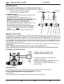
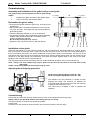
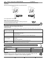
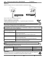
Assembly and installation of the girder trolley on the girder
The girder trolleys can be adjusted to various girder flange
1-1,5 mm
widths.
1.
Establish the girder dimensions (b) (flange width)
2.
Check conformity with the data sheet.
1-1,5 mm
b
Dismantled the girder trolley
Ö Unscrew the load bolt (undo the split pin (6), lock nut (5) and
load bolt (2)).
Ö Set the track width. The distance between the rims must be
min. 2mm and max. 3mm larger than the actual (measured)
girder flange width.
Ö There are adjusting washers (3), (4) on the load bolt.
Ö The spacing dimension (b) is achieved by pushing adjusting
washers from outside to inside (b is increased) or from
inside to outside (b is reduced).
Do not leave out any adjusting washers.
Ö Tighten the lock nut (5) and secure it with the split pin.
1
2
3
7
4
5
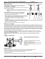
Installation on the girder
Adjust the side plates (1) of the chassis to width “M” with the load bolt (2), adjusting washers (3) and (4), spacer
tube (7) and lock nut (5) and fit them. Tighten the lock nuts and push the unit on to the front of the girder flange. If
this is not possible, the chassis can also be installed on to the raceway girder from underneath. The lock nut on the
side without the drive unit must be removed for this purpose. Pull the chassis halves apart until the chassis can be
pushed on to the girder flange from underneath. Then push the chassis together again to the correct track width,
tighten the lock nut and secure it with the split pin.
The side plates should not be stressed by the lock nut but should still be able to move on the load bolt (2).
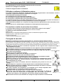
CHD - Trolley: The roller chassis may only be pulled on the load, the load hook or the load chain of the
lifting gear
CHDD – Hoist trolley: Move the hoist trolley only by chain.
Adjusting the anti-tipping protection
Girder trolley 1000 kg (Girder profile 65 - 310)
Girder trolley 2000 kg (Girder profile 88 - 310)
The attitude of the tilt prevention is carried out after
attaching the trolley; The measure "H" between the
lower strap area and the upper line of the axis amounts
to optimize the business to 1 mm.
This value can be changed in order to optimize the
operation.
Commissioning
Ensure that the chains are correctly positioned; they must not be twisted and must hang freely.
Always refer to the operating manual of the lifting gear you are using.
The open meshing on the drive unit should be greased.
Function test:
Carefully move the chassis to the limit position and check the position of the limit stops.
technische Änderungen vorbehalten
design changes under reserve
changements techniques sous réserve
Seite / page 9
6