1
Installation and Operating Instructions
Remote Transmission Device
RAMOC® VD4-ST2
Innotas Produktions GmbH
Friedrich-Engels-Str. 46
D-15745 Wildau
+ 49 (3375) 529649 0
+ 49 (3375) 529649 24
Email: [email protected]
www.innotas-service.de
Last update - 28.07.2014
Page 3/8
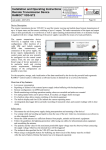
Power supply connection:
The connection has to be made in a dead-voltage state (e.g. remove mains plug
from socket). The polarity and the specified voltage range (refer to technical
specification) have to be observed:
Labelling
Power Clamp
+
GND
Colour of
Meaning
Terminal Clamp
orange
Supply voltage plus
dark grey
Supply voltage minus (GND)
Note: All GND clamps are electrically connected with
each other.
On / off switch:
Using the on / off switch the device can be switched on
or off.
On / off switch
Fuse
Rechargeable battery
connection
Power supply
connection
Configuration of the device:
In order to configure of the remote transmission unit the device has to be connected to a serial port of a PC by
means of a configuration cable (if required, an USB to Serial adapter can be used). Then the device has to be
switched on. Afterwards, the configuration program VD4_Conf has to be started on the PC and using the button
“COM port settings” the serial port has to be selected to which the remote transmission unit is connected. All
further configuration settings are performed via the configuration program VD4_Conf. Finally, the established
serial connection has to be remove and the device has to be restarted by turning it off and on.
Rechargeable battery connection:
If required, a recharchable battery can be connected in order to back up the case of failure of the energy supply.
In any case the polarity of the battery must be observed and a short-circuit of the battery must be avoided:
Labelling
Akku Clamp
+BAT
GND
Colour of
Terminal Clamp
orange
dark grey
Meaning
Rechargeable battery connection plus
Rechargeable battery connection minus (GND)
Wiring of the outputs:
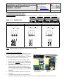
The outputs are implemented by bistable change-over contact relays. As shown on the
adjacent drawing, in the basic state "0", the two right-hand contacts are electrically
connected. By switching-over the output to state "1", the two left-hand contacts will be
connected. It can be configured whether the outputs will automatically be set to the basic
state "0" after switching on the remote transmission unit. Furthermore, it can also be
configured whether outputs which are switched to the state "1" will automatically be reset
to its initial state after a selected time (pulse generator).