1
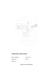
Operating instructions
Machine designation:
Vacuum mixer
Machine type:
D-VM 18
Machine no.
......................
Keep for future reference!
Dear customer,
Thank you for the confidence you have placed in us by purchasing this vacuum mixer.
For this device to be of service to you for many years to come, please take the time to read
these operating instructions carefully, especially before using the device for the first time.
Contents
1
2
3
4
5
6
7
8
9
10
11
Safety.................................................................................................................................. 2
1.1 Intended use .............................................................................................................. 2
1.2 Possible dangers ...................................................................................................... 2
1.3 Approved operators.................................................................................................. 2
1.4 Marking of safety references contained in these instructions.............................. 2
Unpacking the vacuum mixer........................................................................................... 3
Starting up.......................................................................................................................... 3
3.1 Brief description of unit and identification of components................................... 3
3.2 Safety measures at site of installation .................................................................... 5
3.3 Starting up procedure............................................................................................... 5
Bedienung .......................................................................................................................... 6
4.1 Standard program ..................................................................................................... 7
4.1.1 Description of display in standard program ...................................................... 7
4.1.2 Automatic mixing under vacuum after pre-set time .......................................... 7
4.1.3 Adjusting and saving parameters in the standard program.............................. 8
4.1.4 Mixing for a specified time without a vacuum................................................. 10
4.1.5 Creating a vacuum only (e.g. when soaking models)..................................... 11
4.1.5.1 Creating a vacuum without specified time........................................ 11
4.1.5.2 Creating a vacuum with specified time............................................. 12
4.1.6 Freely-selected manual sequence ................................................................. 12
4.1.7 Explanation of settings and method for saving mixing time ........................... 13
4.2 User programs......................................................................................................... 14
4.2.1 Automatic mixing in accordance with individually-created programs ............. 14
4.2.2 Explanation of user program structure ........................................................... 16
4.2.2.1 Changing the alloy name ................................................................. 17
4.2.2.2 Changing the parameters in a single step........................................ 17
4.2.2.3 Changing the program step duration................................................ 17
4.2.2.4 Changing the direction of rotation .................................................... 18
4.2.2.5 Changing the speed......................................................................... 19
4.2.2.6 Changing the vacuum value ............................................................ 19
4.2.3 Structure of a complete user program............................................................ 20
Cleaning/Maintenance..................................................................................................... 22
5.1 Filter test .................................................................................................................. 22
5.2 Changing the filter .................................................................................................. 22
5.3 Soiled contact pin ................................................................................................... 23
5.4 Sintered-metal filter for vacuum control ............................................................... 24
Electrical fusing............................................................................................................... 25
Technical data.................................................................................................................. 25
Drilling guide for wall securing plate (wall unit) ........................................................... 26
Warranty conditions ........................................................................................................ 27
EC declaration of conformity.......................................................................................... 28
Appendix 1 ....................................................................................................................... 29
11.1 Table for user programs ......................................................................................... 29
D-VM 18 - 27.02.02 / Vers.: 1
1
1
1.1
Safety
Intended use
The D-VM 16 vacuum mixer is intended for use in dental laboratories for mixing plaster and
embedding materials under vacuum conditions.
Unauthorized modifications and additions are not permitted for safety reasons!
Attention
The unit is not designed as a medical appliance!
Use on human beings is prohibited!.
1.2
1.3
Possible dangers
-
The vacuum mixer is safe when used as intended. However, when not used properly or
with due care its use can lead to injuries. In no case at all should the stirrer be used without
mixing container. Unguarded stirrer can lead otherwise to.
-
Before maintenance work, cleaning and/or repair work you should switch the unit off at the
main switch and disconnect it from the mains supply (i. e. the mains plug should be pulled).
-
Before accessing any of the incorporated electric components, the unit should be
disconnected from the mains supply!
Approved operators
The operator of the machine should make sure that the operating instructions are accessible to
the operating personnel. The operator should make sure that they have been read and fully
understood by the operating personnel. Only then should they be allowed to operate the
machine.
1.4 Marking of safety references contained in these instructions
Caution
Refers to tips and other particularly helpful pieces of information.
Attention
Refers to particular ways of operation or handling, the non-adherence of which can lead to
malfunctioning, damages or other kinds of trouble.
Danger
Refers to dangerous situations, in which injuries can occur.
2
D-VM 18 - 27.02.02 / Vers.: 1
2
Unpacking the vacuum mixer
Note
Inspect the packaging and unit for transportation damage and report any detected immediately
to the haulage firm and/or supplier.
1.
Place the carton on a flat surface.
2.
Remove the top packaging material.
3.
Push the packaging material away from the unit. Grasp hold of the unit by the lower edge.
4.
The unit (weight approx. 28 kg) should be lifted out of the carton by two persons.
5.
Check the accessories:
−
Documentation
−
Mixer receptacle (300 ml), complete with lid and mixer ...................................no. 016 00 251
−
See delivery note for further possible accessories
3 Starting up
3.1
Brief description of unit and identification of components
The vacuum mixer is equipped with one standard and 11 user programs. Three standard
program parameters can be individually adjusted (priority time, speed of the mixing motor and
vacuum level). Embedding material and plaster are mixed under ideal vacuum conditions. The
powerful, robust gear mixing motor and the maintenance-free, high-performance, two-cylinder
vacuum pump (which can rapidly create a vacuum of 970 mbar) form the sturdy central
components of the unit. The mixing motor is protected against overloading by an overload
switch. The lifting table serves as a holder and guiding mechanism for the mixer receptacle. The
mixer clutch components engage when the lifting table is raised. The mixer receptacle is
simultaneously pressed against the sealing surface and held in position (even without a
vacuum). The procedure can be realised manually or automatically.
The heavy cast-aluminium unit pedestal gives table units great stability. The wall unit is retained
by a stable wall securing plate.
Version: Wall unit
D-VM 18 - 27.02.02 / Vers.: 1
3
Version: Table unit
Illus. 1: Basic unit
1
2
3
4
5
6
7
8
9
4
Unit cover
Unit pedestal (table unit)
Screen
Suction hose
Flange
Mixer receptacle
Lifting table
Wall securing plate (wall unit)
Fixing screw
10
14
15
16
17
18
20
21
Seal
Mains power cable
Interface for PC connection (RS232)
Fuses
Overload switch (12A)
Ultra-fine filter housing
Contact pin
Sintered-metal filter
D-VM 18 - 27.02.02 / Vers.: 1
3.2 Safety measures at site of installation
Table unit:
The supporting surface should be level and
stable, with supporting capabilities suited to the
weight of the vacuum mixer.
Wall unit:
The unit is suspended from a wall securing plate
(8) in which the lifting table (7) which retains the
mixer receptacle (6) is integrated. Suitable fixing
material (dowels, screws and similar) should be
used to secure this plate to a stable wall with
suitable supporting capabilities. The fixing screw
(9) should be screwed in after suspending the
unit.
Illus. 3: Table unit
The unit should be installed in a dust-free
environment. Clearance of approx. 5 cm should
be provided on the left and right side for
ventilation purposes.
The unit is not suitable for use in rooms where
special conditions exist (e.g. corrosive or
potentially explosive atmospheres).
Foreign bodies should be prevented from
penetrating the ventilation openings in the unit.
3.3 Starting up procedure
Illus. 3: Wall unit
Caution
Note
A transportation securing plate (painted red) is located at the rear of the unit. This must be
removed before starting up! (Please retain for use in the future)
1.
Remove the transportation securing plate by unscrewing the three M6 socket screws (SW 5
mm). Keep it in a safe place.
2.
Connect unit to power supply (230V/50Hz).
3.
Switch on unit with main switch (30); the control lamp illuminates green (see Illus. 6, Page 6).
The following is shown in the display (31) after switching on:
•
In standard program mode:
Illus. 4: Display in standard program mode
−
Name of program .......... Î Standard V
−
Priority time ................... Î set at 10 seconds ex works
−
-1
Speed............................ Î set at 250 min ex works
−
Vacuum ......................... Î set at 970 mbar ex works
D-VM 18 - 27.02.02 / Vers.: 1
5
•
In user program mode:
There are 11 user programs. These sequences can be structured to suit requirements.
The parameters of the initial program step are shown in the display:
Illus. 5: Display in user program mode
4
−
Name of alloy .............................. Î e.g. GC Fujirock
−
Program number ......................... Î 4
−
Duration of initial step.................. Î 7 sec.
−
Total duration of program ............ Î 74 sec.
−
Direction of rotation ..................... Î arrow (left or right)
−
Speed.......................................... Î e.g. 350 min
−
Vacuum ....................................... Î e.g. 570 mbar
-1
Operation
Illus. 6: Screen
30
31
32
33
34
6
Main switch
Display
“Start“ button
“Vac“ key
“Mix“ key
35
36
37
38
39
Program selection switch
”Stop“ button
“MF“ multi-function key
“+“ key
“-“ key
D-VM 18 - 27.02.02 / Vers.: 1
4.1 Standard program
4.1.1
Description of display in standard program
1.
Switch on unit.
2.
Set program selection switch to V.
Illus. 7: Program selection switch
3.
Parameters shown in display.
Parameter type
Parameter value
Time (priority time)
10 seconds
Suction time
10 seconds
Manual time
20 seconds
Speed
250 min-1
Vacuum
970 mbar
Languages
German
Illus. 8: Display in standard program mode
4.1.2
Automatic mixing under vacuum after pre-set time
(see Illus. 1, Page 4 and Illus. 6, Page 6)
1.
Set program selection switch to “V“. “Standard V“ appears in the display.
2.
Set the desired mixing time (specified time) with the “+“ or “-“ key, provided it is not intended to
work with the priority time (see section “4.1.3“ for details).
3.
The embedding material or plaster to be mixed is premixed manually in the mixer receptacle,
ensuring that the “max.“ mixing level is not exceeded. The powder should be blended with water
in proportions which do not cause it to surge up when the mixer starts moving.
4.
Press the “Start“ button (8).
The unit is now ready for operation. It only commences running in automatic mode after the
mixer receptacle (6) is pressed against the sealing surface (10) and activates the contact pin
(20) located there.
Automatic program sequence:
1.
The display (31) counts down in seconds, the vacuum pump is running and the vacuum
increases rapidly. The mixer receptacle is now also held in position by the vacuum.
2.
The mixer is activated when approx. 70% of the set vacuum is achieved. The timer also
starts.
3.
The mixer switches off on reaching the “000“ position in the display (31) and a signal
sounds for 3 seconds in the unit.
4.
The vacuum is maintained by the vacuum pump which, in turn, is only deactivated when the
unit is switched off with the ”Stop” button (36). This leads to simultaneous controlled
flooding of the mixer receptacle.
The specified time is shown again in the display (31).
5.
The lifting table (7) and mixer receptacle (6) can be lowered manually to the limit stop when the
pressure gauge indicates “0“ bar.
6.
Remove mixer. The mixture is ready for processing.
D-VM 18 - 27.02.02 / Vers.: 1
7
4.1.3
Adjusting and saving parameters in the standard program
Set program selection switch to “V“. “Prog.Standard V“ appears in the display.
Note
Press the “MF“ key (37) once. “Priority time“ appears in the display.
Note
The following information appears in the display:
-
“next“ (i.e. other parameters are displayed for changing after re-actuation of the “MF“ key).
-
“return“ (i.e. any parameter changes carried out are saved after the “Stop“ button is
actuated. The unit changes to the working menu and is ready for operation).
Illus. 9: Display during adjusting of priority time
Set the desired priority time with the “+“ or “-“ key.
Note
The priority time is set at 10 seconds ex works.
Press the “MF“ key for the second time. “Suction time“ appears in the display.
Illus. 10: Display during adjusting of suction time
The suction time is set at 10 seconds ex works. The suction time should not be altered, as it
is used for testing the degree of filter soiling.
Note
1.
Press the “MF“ key for the third time. “Manual time“ appears in the display (see Section
4.1.4).
Illus. 11: Display during adjusting of manual time
Set the desired manual time with the “+“ or “-“ key.
Note
8
The manual time is set at 20 seconds ex works. Manual time setting is necessary when mixing
for a specified time without a vacuum.
D-VM 18 - 27.02.02 / Vers.: 1
2.
Press the “MF“ key for the fourth time. “Speed“ appears in the display.
Illus. 12: Display during adjusting of speed
Set the desired speed with the “+“ or “-“ key.
The speed is set at 250 min-1 ex works.
Note
3.
Press the “MF“ key for the fifth time. “Vacuum“ appears in the display.
Illus. 13: Display during adjusting of vacuum
Set the desired vacuum with the “+“ or “-“ key.
Note
The vacuum is set at 970 mbar ex works.
4.
Press the “MF“ key for the sixth time to select the desired language. The following appears in
the display.
“1-D
2-E
3-F
4-S“
German
English
French
Spanish
Illus. 14: Display during selection of language
Select the desired language with the “+“ or “-“ key.
5.
Note
Press the Stop button to save settings and terminate the adjusting mode.
Press the “MF“ key as often as necessary when only one parameter is to be changed, stopping
when the desired parameter appears in the display. After setting with the “+“ or “-“ key, press
the Stop button to save settings and terminate the adjusting mode.
D-VM 18 - 27.02.02 / Vers.: 1
9
4.1.4
Mixing for a specified time without a vacuum
(See Illus. 1, Page 4, Illus. 6, Page 6)
Note
Parameters required for mixing without a vacuum are only set in the standard program
(selection switch position V).
1.
The embedding material or plaster to be mixed is premixed manually in the mixer receptacle,
ensuring that the “max.“ mixing level is not exceeded. The powder should be blended with water
in proportions which do not cause it to surge up when the mixer starts moving.
2.
Press the “Mix“ key (34). The following appears in the display (31):
Illus. 15: Appearance in display
−
Mixing time .......................... Î set at 20 sec. ex works
−
-1
Speed .................................. Î set at 250 min ex works
−
Vacuum ............................... Î 000
A prerequisite is that the selection switch is at V.
Note
Changing the mixing time: (see Illus. 11, Page 8)
Press the “MF“ key repeatedly until “Manual time“ appears in the display.
Set the desired manual mixing time with the “+“ or “-“ key.
Changing the speed: (see Illus. 12, Page 9)
Press the “MF“ key repeatedly until “Speed“ appears in the display.
Set the desired speed with the “+“ or “-“ key.
Press the Stop button to save settings and terminate the adjusting mode.
Note
If the speed is newly adjusted the value is also retained in the standard program when the
program starts running (after pressing the “Start“ button).
3.
Position the mixer receptacle (6) with the mounted mixer on the lifting table (7). Raise the lifting
table manually, maintaining the pressure. The mixer engages and is switched on. The timer is
activated.
4.
The mixer can be switched on and off as required while the timer is running by pressing the
“Mix“ key (34).
The speed indication is set at “000 rpm“ in the display if mixing is interrupted.
Note
10
5.
The mixer switches off on reaching the “000“ position in the display (31) and a signal sounds for
3 seconds in the unit.
6.
Move the lifting table (7) downwards. Remove mixer. The mixture is ready for processing.
-
The contact pin (20) is deactivated on reaching the “000“ time in the display (31).
-
The contact pin (20) is activated by pressing the “Stop“ button (36) or “Mix“ key.
D-VM 18 - 27.02.02 / Vers.: 1
4.1.5
Creating a vacuum only (e.g. when soaking models)
Use receptacles with special lids (without the mixer) for soaking models!
-
Special lid for 300 ml receptacles ................................................................ Order no.: 32034
-
Special lid for 600 ml receptacles ................................................................ Order no.: 32035
-
Special lid for 1000 ml receptacles .............................................................. Order no.: 32039
4.1.5.1 Creating a vacuum without specified time
(See Illus. 1, Page 4, Illus. 6, Page 6)
1.
„Vac“-Taste (33) drücken.
Illus. 16: Appearance in display
2.
3.
4.
The vacuum pump only commences running after the mixer receptacle (6) is pressed against
the sealing surface (10) and activates the contact pin (20) located there.
The vacuum is normally created without a time limit.
-
The time setting “000“ is shown in the display (31), meaning the vacuum pump is operating
in continuous mode (manual mode).
-
The vacuum pump is switched on and off by pressing the “Vac“ key (33) again.
The unit creates a vacuum in accordance with the setting in the standard program.
Illus. 17: Appearance in display
5.
The vacuum is reduced to 0 bar after actuation of the “Vac“ key or “Stop“ button. Only then can
the lifting table (7) with the mixer receptacle (6) be lowered manually to the limit stop.
D-VM 18 - 27.02.02 / Vers.: 1
11
4.1.5.2 Creating a vacuum with specified time
(See Illus. 1, Page 4, Illus. 6, Page 6)
1.
Press “Vac“ key (33).
2.
Use the “+“ or “-“ key if a specific vacuum time is to be set.
Note
Brief actuation of the “+“ or “-“ key changes the display by one step. Pressing for a lengthier
period changes the display in rapid motion.
3.
The maximum time which can be set is 999 sec.
Illus. 18: Appearance in display
4.1.6
4.
The vacuum pump only commences running after the mixer receptacle (6) is pressed against
the sealing surface (10) and activates the contact pin (20) located there.
5.
The timer starts automatically after a brief delay, the display (31) simultaneously counting
backwards in seconds.
6.
A signal sounds for 3 sec. when the “000“ timer position is reached. The vacuum pump remains
in operation (the LED in the “Vac“ key (33) remains illuminated).
7.
The vacuum pump is switched off with the “Stop“ key (36) and/or “Vac“ key (33).
8.
The lifting table (7) and mixer receptacle (6) can be lowered manually to the limit stop when the
display indicates “000 mbar”.
Freely-selected manual sequence
(see Illus. 6, Page 6)
The vacuum and mixing sequences can be freely selected.
12
−
The respective functions can be switched on and off in all four combinations with the “Vac“
(33) and “Mix“ (34) keys. This blocks the “Start“ key (32) function.
−
Pressing a key actuates the LED illumination in the key, the function being triggered when
the key is released.
−
The “Vac“ (33) and “Mix“ (34) key functions are blocked in automatic mode after the “Start“
key (32) has been activated. All functions are switched off when the “Stop“ key (36) is
actuated.
D-VM 18 - 27.02.02 / Vers.: 1
4.1.7
Explanation of settings and method for saving mixing time
(Illus. 6, Page 6)
1.
The unit is programmed ex works so that the number 10 is shown in the display (31) when
starting up (switching on with the main switch (30)). This means that the mixing duration is 10
seconds when the program is running. This saved mixing time is the priority time.
2.
A mixing time selected for processing which deviates from the priority time can be altered by
pressing the “+“ or “-“ keys. The time altered in this manner is known as the specified time. This
specified time is retained for subsequent mixing procedures (provided it is not altered again)
until the unit is switched off with the main switch (30). Reactivation of the unit causes the saved
priority time to be displayed again (i.e. mixing will have a duration of 10 seconds while the
program is running (as set ex works)).
3.
The residual running time (i.e. the remain working sequence duration) can be changed by
pressing the “+“ or “-“ keys (“Mixing“ (see Section “4.1.2“ and “4.1.4“) or “Creating vacuum with
specified time“ (see Section “4.1.5.2“)) during an active working sequence. The time display (31)
is stopped by pressing the “+“ or “-“ keys. The internal electronic clock continues to run in the
background. The time required while changing the residual running time is automatically
subtracted from the new residual running time and skipped over in the display (31). A residual
running time change only applies to the currently active working sequence (i.e. it is not saved).
4.
Altering and saving the priority time (see Illus. 9, Page 8):
Note
Set program selection switch at V
−
Press the “MF“ key once. “Priority time“ appears in the first line of the display (31)
The priority time is set at 10 seconds ex works.
Note
−
Set the desired priority time with the “+“ or “-“ key.
−
Press the “Stop“ button to save the new priority time and terminate the adjusting mode.
It is possible to work at any time with a time deviating from the priority time (the so-called
specified time) (see above under Point 2).
5.
Note
Manual adjusting of mixing time (see Illus. 11, Page 8):
−
Set program selection switch at V
−
Press the “MF“ key repeatedly until “Manual time“ appears in the first line of the display
(31)
The manual time is set at 20 seconds ex works.
Note
−
Set the desired mixing time with the “+“ or “-“ key.
−
Press the “Stop“ button to save the new manual time and terminate the adjusting mode.
The saved priority and manual times are retained by the memory, even if the unit is switched off
or a power failure occurs.
6.
Note
−
The maximum time which can be set is 999 sec.
It is not necessary to alter all parameters. All parameters are retained after a parameter is
altered (for example) and the “Stop“ button is actuated.
D-VM 18 - 27.02.02 / Vers.: 1
13
4.2 User programs
Note
User programs 1-11 are selected with the program selection switch.
The user program is activated with the “Start“ button and terminated/interrupted with the “Stop“
button. The “Vac“ and “Mix“ keys do not react if a user program is selected and remain
functionless.
4.2.1
Automatic mixing in accordance with individually-created programs
1.
Set program selection switch to desired program number (no. 1-11).
Illus. 19: Program selection switch set to user program no. 4
2.
The embedding material or plaster to be mixed is premixed manually in the mixer receptacle,
ensuring that the “max.“ mixing level is not exceeded. The powder should be blended with water
in proportions which do not cause it to surge up when the mixer starts moving.
3.
Press the “Start“ button (32).
The unit is now ready for operation. The program only takes over the sequence of all functions
(as described below) if the mixer receptacle (6) is raised together with the lifting table and
pressed against the sealing surface (10), activating the contact pin (20) located there.
User program sequence:
The parameters of the initial step and the total duration of the selected user program are
displayed after the user program is selected and the unit is switched on.
Illus. 20: Display prior to program activation
Illus. 21: Display (e.g. during the initial step)
Line 1: Name of alloy, program number
st
Line 2: Mixing time of 1 step 7 sec. (max. 254 seconds) and total program duration 74 secs.
(max. 999 seconds)
Line 3: Direction of rotation ( Å or Æ ), speed 0 (zero) rpm or adjustable in range 100-600 rpm
Line 4: Vacuum 0 (zero) mbar or adjustable in range 150-970 mbar
Explanation of line 1:
In addition to the alloy name, the step number and the number of the selected program is
displayed on the right –hand side immediately after the program commences.
14
D-VM 18 - 27.02.02 / Vers.: 1
Explanation of line 2:
The display provides information on the time sequence of each step and, simultaneously, on the
total duration of the entire program.
−
The next program step is automatically activated when step duration “000“ is reached
(the set step duration has expired).
−
The mixer switches off and a signal sounds for 3 seconds when total duration “000“ is
reached (the total program duration has elapsed).
−
The vacuum pump maintains the vacuum at the level of the set vacuum in the last program
step (see Illus. 22, Page 15).
Illus. 22: Display on completion of entire program
−
The pump is switched off by pressing the “Stop“ button (36). This leads to simultaneous
controlled flooding of the mixer receptacle.
−
The settings of the initial program step are shown again in the display.
Illus. 23: Display prior to actuation of “Start“ key
Explanation of line 3:
The allocated direction of rotation (e.g. right Æ) and speed (e.g. 350 rpm) are shown for each
active program step.
Illus. 24: Appearance in display
Explanation of line 4:
The allocated vacuum (e.g. 570 mbar) is shown for each active program step.
Illus. 25: Appearance in display
D-VM 18 - 27.02.02 / Vers.: 1
15
4.2.2
Explanation of user program structure
1 Name of alloy: .........................................................................................................................
Step no.
Duration of
step
2
3
sec.
Direction of
rotation
Speed
Vacuum
4
5
6
rpm (min-1)
mbar
Å
left
Æ
right
1
6
Å
350
570
2
10
Æ
250
250
3
7
Æ
0
600
4
8
Å
400
0
5
12
Æ
200
970
M
M
M
M
M
M
M
M
M
M
16
Remarks
Program end
255
Table 1: A user program can consist of a maximum of 15 steps.
Note
It is possible to call up the individual steps of a program by actuating the “MF“ key if the program
selection switch is set to a desired program number (1-11).
1 Name of alloy: GC Fujirock.....................................................................................................
Step no.
Duration of
step
2
3
sec.
Direction of
rotation
Speed
Vacuum
4
5
6
rpm (min-1)
mbar
Å
left
Æ
right
1
7
Æ
350
570
2
10
Å
250
250
3
7
Æ
0
600
4
8
Å
400
0
5
12
Æ
200
970
6
8
Å
500
970
7
10
Å
200
400
8
255
M
M
M
M
16
Remarks
Number 255 is
program end
M
M
M
M
M
M
255
Table 2: Example of program with 7 steps
16
D-VM 18 - 27.02.02 / Vers.: 1
4.2.2.1 Changing the alloy name
Note
The alloy name can have a maximum of 11 characters.
1.
Select the program to be changed with the program selection switch.
2.
Press the “MF“ key once (thus calling up the display mode)
3.
Press the “+“ key, immediately followed by the “MF“ key (almost simultaneously):
-
4.
Note
The flashing cursor occupies the position of the first character
Press the “+“ or “-“ key to select the desired character in the table below.
The “+“ key increases the character displayed (e.g. turns “E“ into “F“).
The “-“ key decreases the character displayed (e.g. turns “E“ into “D“).
!
/ 0
> ?
M N
“
1
@
O
#
2
A
P
$
3
B
Q
%
4
C
R
&
5
D
S
‘
6
E
T
(
7
F
U
)
8
G
V
*
9
H
W
+
:
I
X
,
;
J
Y
- .
< =
K L
Z
Table 3: Letter and character sequence
5.
Press the “MF“ key to move the cursor to the next position in order to change the following
character.
6.
Repeat Point 4 and 5 until the name has been completely constructed.
7.
The “MF“ key should be held depressed after the alloy is completed (it need not contain all of
th
the 11 characters) until the 12 position is reached. The unit automatically carries out a warm
th
restart when the 12 position is reached.
8.
The unit is ready for operation.
4.2.2.2 Changing the parameters in a single step
Note
A program can consist of a maximum of 15 program steps.
1.
Select the program to be changed with the program selection switch.
2.
Press the “MF“ key repeatedly until the desired program step is displayed.
3.
Changing parameters in a selected program step is described below.
4.2.2.3 Changing the program step duration
Note
The maximum duration of a function should not exceed 254 seconds.
Selection of a duration of 255 seconds causes an interruption or the end of a program after the
current step.
1.
Select the program to be changed with the program selection switch.
2.
Press the “MF“ key repeatedly until the desired program step is displayed (e.g. 01).
D-VM 18 - 27.02.02 / Vers.: 1
17
Illus. 26: Appearance in display
3.
Press the “+“ or “- “ key:
−
The flashing cursor jumps to the position of the time to be changed.
4.
Press the “+“ or “- “ key to set the desired time value.
5.
Press the “MF“ key repeatedly until the vacuum value is emphasised by the cursor.
6.
Press the “MF“ key once more. The adjusting mode of the selected program step is quit.
7.
Press the “MF“ key repeatedly until the desired program step is displayed if the program step
duration is to be changed in another program step. The further procedure is as described from
Point 3 onwards.
8.
Press the “Stop“ key. The unit automatically carries out a warm restart.
9.
The unit is ready for operation.
All parameters in the initial program step of the selected program are shown in the display after
the warm restart.
Note
4.2.2.4 Changing the direction of rotation
1.
Select the program to be changed with the program selection switch.
2.
Press the “MF“ key repeatedly until the desired program step is displayed.
3.
Press the “+“ or “- “ key:
-
Place the flashing cursor on the position of the program step duration.
4.
Press the “MF“ key once to position the flashing cursor on the direction of rotation arrow.
5.
Press the “+“ or “- “ key to set the desired direction of rotation (right Æ or left Å).
Illus. 27: Appearance in display
6.
Press the “MF“ key repeatedly until the vacuum value is emphasised by the cursor.
7.
Press the “MF“ key once more. The adjusting mode of the selected program step is quit.
8.
Press the “MF“ key repeatedly until the desired program step is displayed if the direction of
rotation is to be changed in another program step. The further procedure is as described from
Point 3 onwards.
9.
Press the “Stop“ key. The unit automatically carries out a warm restart.
10.
18
The unit is ready for operation.
D-VM 18 - 27.02.02 / Vers.: 1
4.2.2.5 Changing the speed
The speed can be set within the speed range of 100-600 min-1 or at zero.
Note
1.
Select the program to be changed with the program selection switch.
2.
Press the “MF“ key repeatedly until the desired program step is displayed.
3.
Press the “+“ or “- “ key:
-
Place the flashing cursor on the position of the program step duration.
4.
Press the “MF“ key twice to position the flashing cursor on the speed value.
5.
Press the “+“ or “- “ key to set the desired speed.
Illus. 28: Appearance in display
6.
Press the “MF“ key repeatedly until the vacuum value is emphasised by the cursor.
7.
Press the “MF“ key once more. The adjusting mode of the selected program step is quit.
8.
Press the “MF“ key repeatedly until the desired program step is displayed if the speed is to be
changed in another program step. The further procedure is as described from Point 3
onwards.***
9.
Press the “Stop“ key. The unit automatically carries out a warm restart.
10.
The unit is ready for operation.
4.2.2.6 Changing the vacuum value
Note
The vacuum can be set within the vacuum range of 150-970 mbar or at zero.
1.
Select the program to be changed with the program selection switch.
2.
Press the “MF“ key repeatedly until the desired program step is displayed.
3.
Press the “+“ or “- “ key:
-
Place the flashing cursor on the position of the program step duration.
4.
Press the “MF“ key three times to position the flashing cursor on the vacuum value.
5.
Press the “+“ or “- “ key to set the desired vacuum.
Illus. 29: Appearance in display
6.
Press the “MF“ key once more. The adjusting mode of the selected program step is quit.
7.
Press the “MF“ key repeatedly until the desired program step is displayed if the vacuum is to be
changed in another program step. The further procedure is as described from Point 3 onwards.
8.
Press the “Stop“ key. The unit automatically carries out a warm restart.
9.
The unit is ready for operation.
D-VM 18 - 27.02.02 / Vers.: 1
19
4.2.3
Structure of a complete user program
- Fill out the program table (see Appendix 1). The parameter values should be equivalent to the
respective alloy manufacturer’s specifications.
Note
See Table 1 and Table 2 on Page 16 for a template and example of a program table.
- All parameter values can be entered in the display on the basis of the program table:
1.
Entering the alloy name 1, (see Section 4.2.2.1, Page 17).
2.
Entering the parameters for the initial program step:
−
3.
4.
Press the “MF“ key once. The initial program step is displayed.
Changing the step duration 3:
-
Press the “+“ or “- “ key to position the cursor on the program step duration.
-
Press the “+“ or “- “ key to set the desired time value.
Changing the direction of rotation 4:
−
Press the “MF“ key to position the cursor on the on the direction of rotation arrow.
Press the “+“ or “- “ key to set the desired direction of rotation (right Æ or left Å).
5.
6.
7.
Changing the speed 5:
−
Press the “MF“ key once to position the cursor on the speed value.
−
Press the “+“ or “- “ key to set the desired speed.
Changing the vacuum value 6:
−
Press the “MF“ key once to position the cursor on the vacuum value.
−
Press the “+“ or “- “ key to set the desired vacuum.
−
Press the “MF“ key once more to save the parameter values of the initial program step and
to change to the display mode of the second program step.
Entering the parameters for the second program step:
All parameters of the second and following steps are entered as described above from Point 3
onwards.
8.
Determining the program end:
It is imperative that a line be created after the last program step to identify the end of the user
program if the user program has been entered in accordance with the previously-created table.
The end of the user program is achieved as a program step when the number 255 is entered
(see Table 2, Page 16)
9.
−
Press the “+“ or “- “ key to position the cursor on the program step duration.
−
Press the “+“ or “- “ key to set the time value at 255.
−
Press the “MF“ key repeatedly until the vacuum value is emphasised by the cursor
−
Press the “MF“ key once more. The adjusting mode of the last program step is quit..
−
Press the “Stop“ key. The unit automatically carries out a warm restart.
The unit is ready for operation.
Note
All parameters in the initial program step of the selected program are shown in the display after
the warm restart.
Note
A program created once can be interrupted at any position.
(e.g. a user program has 12 steps. However, the user program will only process steps 1-8 if
the number 255 is set as the step duration in program step 9. The remaining program steps 912 are ignored and not imported into the user program working sequence.
20
D-VM 18 - 27.02.02 / Vers.: 1
Table 3:
1 Name of alloy GC Fujirock: ....................................................................................................
Step no.
Duration of
step
Direction of
rotation
Speed
Vacuum
2
3
4
5
6
rpm (min-1)
mbar
sec.
Å
left
Æ
right
1
6
Å
300
500
2
10
Æ
250
250
3
7
Æ
0
600
4
8
Å
400
0
5
12
Æ
200
970
6
8
Å
500
970
7
10
Å
200
600
8
8
Æ
450
750
9
255
Å
650
150
10
7
Æ
0
600
11
8
Å
400
0
12
12
Æ
200
970
13
255
M
M
M
M
Remarks
New program
end
Previous
program end
M
M
M
M
M
M
16
D-VM 18 - 27.02.02 / Vers.: 1
21
5
Cleaning/Maintenance
5.1 Filter test
(see Illus. 6. Page 6)
Note
The filter test should only be carried out in the standard program.
1.
This test program is used to check the degree of filter soiling.
2.
Position the 600ml mixer receptacle with the mounted mixer on the lifting table and raise
manually. The lid of the mixer receptacle is pressed against the sealing surface (10) and
activates the contact pin (20).
3.
The filter test is now started as follows:
-
Press and hold down the “Stop“ button (36),
-
Then press the “+“ key briefly at the same time. The word “Filter test“ appears in the display
-
Release the “Stop“ button (36).
4.
The keys (32), (33) and (34) illuminate during the filter test.
5.
The timer starts with the value “010“ in the display (31) and then counts backwards in seconds.
The residual running time can be read in the display. The higher the time value of this residual
running time, the lower the degree of soiling in the unit filters.
6.
The appearance of “Filter OK“ in the display indicates that the filters are suitable for operation.
7.
The appearance of “Filter Error“ in the display indicates that the filters or hoses are soiled (see
Section “5.2“).
8.
The message remains in the display until the “Stop“ key (36) is actuated.
5.2 Changing the filter
(see Illus. 31, Page 24)
Experience has shown that dust or even mixture can be sucked in during mixing, so a
preliminary filter (43) and ultra-fine filter (19) are fitted in the suction inlet, both of which are
easily accessible. These should be changed on becoming soiled.
1. The ultra-fine filter (19) is located in the ultra-fine filter holder (18). Turning to the left opens the
bayonet lock, and the ultra-fine filter holder can be removed along with its filter. Insert the new
filter cartridge in the unit. Position the ultra-fine filter holder in the unit and lock by turning to the
right.
2.
The preliminary filter (43) is built into the suction hose (4). The entire suction hose assembly
must be replaced if it is soiled (the replacement suction hose assembly can be obtained from
Harnisch+Rieth (order no.: 016 00 513)):
3.
Removing the old suction hose:
4.
22
-
Release the unlocking ring (26) with a screwdriver (40) or similar by applying pressure and
pull the quick adjustment angle (42) downwards out of the counterpart (41).
-
Open the union nut (50) and pull off the second end.
Inserting a new suction hose assembly:
-
Insert the quick adjustment angle (42) into the counterpart (41) right up to the stop.
-
Insert the hose end with support sleeve (46) into the screw nipple (45) and tighten the union
nut (50).
D-VM 18 - 27.02.02 / Vers.: 1
5.3 Soiled contact pin
(see Illus. 30. page 23)
The guide (24) should be unscrewed with a suitable slot screwdriver (right-hand thread) if the
contact pin (20) becomes soiled as a result of defects on the protective silicone cap (22).
Note
Ensure when unscrewing or tightening with the screwdriver that the interior of the guide (24) and
the slot are not damaged (burr formation), as this can impair the contact pin's ease of
movement (20).
Clean the contact pin (20) and guide (24) and ensure that ease of movement exists. Reinsert in
a dry state. Replace the silicone protection cap (22)
Illus. 30: Contact pin with protective silicone cap and sintered-metal filter
20 Contact pin
21 Sintered-metal filter
D-VM 18 - 27.02.02 / Vers.: 1
22 Protective silicone cap
24 Guide for contact pin
23
5.4 Sintered-metal filter for vacuum control
(see Illus. 30, Page 23 and Illus. 31, Page 24)
−
An extreme delay in the creation of the vacuum or its complete failure is an indication that
the sintered-metal filter (21) should be replaced (as an initial step).
−
Use a 7 mm wrench.
Illus. 31:
10
18
19
20
21
24
26
40
41
24
Seal (seal edge)
Ultra-fine filter housing
Ultra-fine filter
Contact pin
Sintered-metal filter
Guide for contact pin
Unlocking ring
Screwdriver
Counteracting part
42
43
45
46
47
48
49
50
Quick adjustment angle
Preliminary filter
Screw nipple
Hose end with support sleeve
Sealing surface
Suction hose
Clamping ring (clip)
Union nut
D-VM 18 - 27.02.02 / Vers.: 1
6
Electrical fusing
Danger
−
The power connection (14) is protected with two 5 A/T main fuses (16).
−
The control (PCB) is protected with the 10 A/T and 1A/M fine fuse. It is located on the PCB
in the unit behind the screen.
−
The mixing motor is protected with an overload switch (17) (12 A).
−
The electrical components can be accessed by removing the unit cover (1).
Switch off the unit and pull out the mains power supply plug before removing the cover.
1
14
16
17
Illus. 32: Electrical fusing
7
Cover
Mains power connection (230 V/50 Hz)
2x main fuses (5 A/T)
Overload switch
Technical data
Machine designation
: Vacuum mixing unit
Machine type
: D-VM 18
Unit dimensions
: Width
Depth
Height
Height
Electrical connection
: 230 Volt/50 Hz
Overvoltage category
: II
Power consumption
: max. 420 W
Mixer speed
-1
-1
: n=100-600 min und n=0 min
Vacuum
: p=150-970 mbar (underpressure) and p=0 mbar
Schalldruckpegel
: 52 dB(A)
Electrical fusing
: 2x 5 A/T
1x 12 A/T
Weight
: approx. 32 kg (table unit)
approx. 27 kg (wall unit)
Mixer receptacle capacities
: 300 ml (standard)
60 ml, 150 ml, 600 ml u. 1000 ml (options)
(1000 ml mixer receptacle to be used without lifting table)
D-VM 18 - 27.02.02 / Vers.: 1
380 mm,
355 mm,
520 mm (wall unit)
540 mm (table unit)
(mains power connection)
(overload switch for mixing motor)
25
8
Drilling guide for wall securing plate (wall unit)
-
Use the wall securing plate as a template.
-
See Section 3.2 for more details on the selection of wall securing material.
Illus. 33: Drilling guide for wall securing plate (wall unit)
26
D-VM 18 - 27.02.02 / Vers.: 1
9
Warranty conditions
This device conforms to the present safety regulations and was subjected to extensive testing
before leaving the works.
We grant 12 months guarantee, in which we are obliged to carry out all repairs resulting from
material or fabrication faults free of charge.
The warranty expires if repairs are not carried out by specialized dealers or by us.
Replacement for reasons covered by the guaranty does not lead to an extension of the original
guaranty period.
Normal wear and tear or damages resulting from incorrect operation are not covered by the
terms of warranty.
In order to be able to provide you with a comprehensive service we ask you to fill out the
guarantee return form (attached at the beginning of these instructions) and send it to us by fax
or letter (window envelope).
Fax-Nr.: 0 71 81/ 73 13 9
------------------------------------------------------------------------------------------------------------- für Fensterumschlag hier falten ----
Copy
Guarantee return form
Bezeichnung
der Maschine:
Vacuum mixer
Maschinen-Typ:
D-VM 18
Maschinen-Nr.:
Kaufdatum:
Händler/Depot:
Maschinenbau
Harnisch+Rieth GmbH & Co.
Postfach 1260
Absender:
D-73644 Winterbach
Datum/Unterschrift:
10 EC declaration of conformity
as stipulated by the EC directive for machines
89/392/EEC, Appendix II A
We herewith declare that due to its design the machine specified below is in conformity with the
basic safety and health requirements of the EC directives.
In the event of modifications of the machine not approved by us this certificate looses its
validity.
Name of the manufacturer
Address of the manufacturer
Machine designation
Machine type
:
:
:
:
Harnisch+Rieth
Küferstraße 14-16, 73650 Winterbach
Vacuum mixer
D-VM 18
The following pertinent EC directives were applied:
EC machine directive (89/392/EEC), corresponding to 9. GSG regulation of 12.05.93
EC low voltage directive (73/23/EEC), corresponding to 1. GSG regulation of 11.06.79
EC EMC directive (89/336/EEC), corresponding to EMC law of 09.11.92
Following harmonizing standards were applied:
DIN EN 292
DIN EN 61 010-1
DIN EN 55 014
DIN EN 55 104
:
:
:
:
Safety of machines.
Safety regulations for electrical measuring, controlling and laboratory devices.
Interference suppression of electrical apparatus and installations.
Electromagnetic compatibility, noise resistance requirements (category I).
A technical documentation is available.
The operation instructions belonging to the machine are also available.
Director of the Quality Control Department
Winterbach, 01st September 2000
28
D-VM 18- 27.02.02 / Vers.: 1
11 Appendix 1
11.1 Table for user programs
Table for program no.: ............................
Name of alloy: .............................................................................................................................
Step no.
Step
duration
sec.
Direction of
rotation
Å
left
Æ
right
Speed
Vacuum
rpm (min-1)
mbar
Remarks
1
2
3
4
5
6
7
8
9
10
11
12
13
14
15
16
Notes:
..................................................................................................................................................................
..................................................................................................................................................................
..................................................................................................................................................................
D-VM 18 - 27.02.02 / Vers.: 1
29